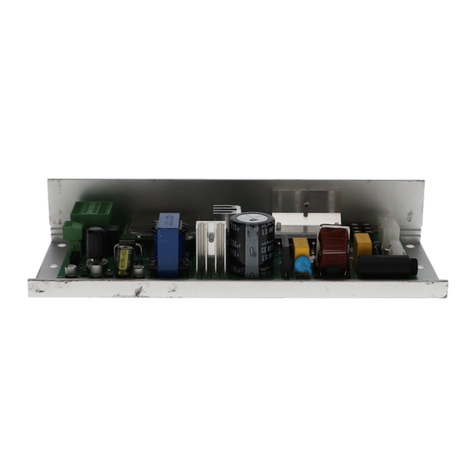
Nabco U30 Owner's manual

S82 W18717 Gemini Drive
Muskego, Wisconsin 53150
Phone: (877) 622-2694
Fax: (888) 679-3319
www.nabcoentrances.com
Technical Support: (866) 622-8325
Part #15-9000-30
Rev. 3/12/13
WARNING
• Turn OFF all power to the Automac Door if a Safety System is not working.
• Instruct the Owner to keep all power turned OFF unl correcve acon can be achieved by a NABCO
trained technician. Failure to follow these pracces may result in serious consequences.
• NEVER leave a Door operang without all Safety detecon systems operaonal.
U30 Microprocessor Control
Setup and Programming Manual
Soware Version D
(For Sliding Door Systems)
DN0079

Rev. 3-12-13 Part #15-9000-30
www.NabcoEntrances.com U30 Microprocessor Control
i
Table of Contents
Warning Labels .................................................................... ii
General Safety Recommendaons ....................................................iii
CHAPTER 1: SCOPE.......................................................1-4
Secon 1a: To the Installer ...........................................................1-4
Secon 1b: Objecve................................................................1-4
CHAPTER 2: GETTING STARTED ............................................2-5
Secon 2a: About the U30 Microprocessor Control .......................................2-5
Secon 2b: Specicaons ............................................................2-5
CHAPTER 3: INPUT AND OUTPUT FEATURES.................................3-7
CHAPTER 4: INITIAL STARTUP ........................................... 4-10
Secon 4a: Wiring .................................................................4-10
Secon 4b: The Handy Terminal ......................................................4-10
Secon 4c: Connecng the Handy Terminal ............................................4-11
Secon 4d: Inializaon of the Handy Terminal Display ..................................4-12
Secon 4e: Disconnecng the Handy Terminal..........................................4-12
Secon 4f: Determine Correct Handing ................................................4-12
Secon 4g: Seng the Stroke of the Slide Door .........................................4-12
CHAPTER 5: ADJUSTMENT PROCEDURES.................................. 5-14
Secon 5a: Standard Funcon Adjustments ............................................5-14
Secon 5b: Feeling Adjustments .....................................................5-15
Secon 5c: Special Funcon Adjustments ..............................................5-16
Secon 5d: History Data ............................................................5-19
Secon 5e: Programming the Extra Funcon Adjustments ................................5-20
Secon 5f: Programming Flow Chart ..................................................5-24
CHAPTER 6: TROUBLESHOOTING ........................................ 6-25

ii
U30 Microprocessor Control www.NabcoEntrances.com
Part #15-9000-30 Rev. 3-12-13
WARNING LABELS
Warning labels are universal and used to alert an individual of potential harm to one’s self or to others. The following warning
labels are listed in a hierarchy order that denes the most potential danger rst, and the least potential danger last. Please refer
to this page in the event that a warning label is displayed within this manual and further denition needs to be explained.
Indicates potentially dangerous situations. Danger is used when there is a
hazardous situation where there is a high probability of severe injury or death.
It should not be considered for property damage unless personal injury risk
is present.
Indicates a hazardous situation which has some probability of severe injury.
It should not be considered for property damage unless personal injury risk
is present.
Indicates a hazardous situation which may result in a minor injury. Caution
should not be used when there is a possibility of serious injury. Caution should
not be considered for property damage accidents unless a personal injury risk
is present.
Notice: Indicates a statement of company policy as the message relates to the personal
safety or protection of property. Notice should not be used when there is a
hazardous situation or personal risk.
DANGER
WARNING
CAUTION

Rev. 3-12-13 Part #15-9000-30
www.NabcoEntrances.com U30 Microprocessor Control
iii
GENERAL SAFETY RECOMMENDATIONS
Read, study and understand general safety recommendations, warning labels,
installation and operating instructions contained in, or referenced in this manual
before operating. If you do not understand the instruction, ask a qualied
technician. Failure to do so may result in bodily injury, or property damage and
will nullify all warranties.
Notice: This manual and the owner’s manual must be given to and retained by the
purchasing facility or end user.
Disconnect all power to the junction box prior to making any electrical
connections. Failure to do so may result in serious personal or fatal injury. When
uncertain whether power supply is disconnected, always verify using a voltmeter.
Notice: Wiring must meet all local, state, federal or other governing agency codes.
All electrical troublshooting or service must be performed by trained, qualied
electrical technicians and comply with all applicable governing agency codes.
Do not place nger or uninsulated tools inside the electrical controller. Touching
wires or other parts inside the enclosure may cause electrical shock, serious
injury or death.
If the door appears broken or does not seem to work correctly, it should be
immediately removed from service until repairs can be carried out or a qualied
service technician is contacted for corrective action.
WARNING
DANGER
CAUTION
DANGER
CAUTION

Scope 1-4
U30 Microprocessor Control www.NabcoEntrances.com
Part #15-9000-30 Rev. 3-12-13
CHAPTER 1: SCOPE
Secon 1a: To the Installer
The purpose of this manual is to familiarize the installer and purchaser with the proper setup and
programming of the U30 Microprocessor Control. It is essential that this equipment be properly
installed and operational before the door is used by the public. It is the installer’s responsibility to
inspect the operation of the entrance system to be sure it complies with any applicable standards.
In the United States, ANSI Standard 156.10 is used to cover Slide door systems. Other local
standards or codes may apply. Use them in addition to the ANSI standards.
Instruct the building owners and operator on the essentials of the operation of the U30
Microprocessor Control. The owner should follow these instructions to determine whether the
door is operating properly and should immediately call for service if there is any malfunction.
Secon 1b: Objecve
The U30 Microprocessor Control is designed to be installed within the Header of all Slide door
systems. This manual offers step by step instructions.

Rev. 3-12-13 Part #15-9000-30
www.NabcoEntrances.com U30 Microprocessor Control
2-5 Geng Started
CHAPTER 2: GETTING STARTED
Secon 2a: About the U30 Microprocessor Control
The U30 Microprocessor Controller (P/N 24-8901-30) is utilized on all GT-1175 Slide Door
systems to control numerous operating characteristics that include (but not limited to): speed,
recycling sensitivity and reduced opening width. Please see .
Figure 2-1 U30 Microprocessor Control
DN 0650
RELATED DEVICES・16P
12
13
14
15
16
No.
11
10
9
8
7
6
5
4
3
2
1
SYMBOL
H
M0
9DC12V
SQ
OUT
Common
N/C
N/O
OUT.A
OUT.B
OUT.C
7
BA
62
SLS
M1
6B
7
61
Sequential Activation
Auxiliary Output (Open-Collector)
5Amax.(0-20V), 3.2Amax.(20-30V)
30V(42.4Vpeak)max.
Contact Output (Class2 Load only)
12VDC-(Common)
FUNCTION [SLIDING DOOR]
Reduced Opening Switch
Breakout Detector
Sidelite Presence Sensor
Exterior Activation
Holding Beam
Interior Activation
12VDC-(Common)
12VDC+
Mode Switch (see Mode SW Usage shown left)
CAUTION
!
Do not disassemble the control box.
There are no user serviceable parts
inside.
To maintain warranty,repairs must be
made by authorized NABCO facilities.
Adjustments to the door can only be made
with the NABCO Handy Terminal.
GYRO TECH
NABCO
fire
ly.
Mode SW Usage
Gnd
GndGnd
Open
Open
Open
Gnd
Open
M0
M1
MODE
TWO WAY
ONE WAY
NIGHT
HOLD OPEN
HANDY TERMINAL・6P
248901-
Microprocessor Controller
No.
To protect against risk of
or electric shock,use only the
certified NABCO power supp
WARNING
MOTOR・12P
ERROR
POWER
BA
62
H
6B
61
INDICATORS
POWER・2P
20VAC 50/60Hz
!
!
!
!
The U30 Microprocessor Controller is also utilized to output power to accessories and/or
auxiliary equipment such as:
►Sensors
►Modules
There are times when the U30 Microprocessor Controller is not utilized to output power because
some accessories and/or auxiliary equipment are shipped with it’s own dedicated power supply.
Secon 2b: Specicaons
Table 2-1
Electricity Description
Power Source 20 VAC (±10%) 50-60Hz, 100 VA (Class 2)
(Use genuine Class 2 power supply module ONLY)
Current Consumption Max. 5A
Power Output
(#9DC, 12V and #7)
12 VDC 0.35 amps (350 mA)
Class 2 Power Supply
Output Rating
Relay Output
XMax. 30V (42.4V peak)
XMax. 5A (0 to 20V) or 3.2A (20 to 30V)
XClass 2 Load Only
Output Rating
(# OUT and #7)
Open collector Transistor Output
►Max. 30V (42.4V peak)
►Max 50mA
►Class 2 Load Only

Geng Started 2-6
U30 Microprocessor Control www.NabcoEntrances.com
Part #15-9000-30 Rev. 3-12-13
Table 2-2
Specification Description
Recommended Temperature Range -4° to 140°F (-20° to +60° C)
Maximum recommended door weight 600 pounds total
(300 pounds each for a bi-part or 600 pounds for a single)
Hold Open time delay 0 to 67 seconds
Door Movement range 4 to 137 inches (100 to 3500 millimeters)
Door Movement range for Limited Door
Opening Feature
4 to 137 inches (100 to 3500 millimeters)
2 to 5 inches (50.8 to 127 millimeters)
Function LED
LED Display Power Red
(LED will blink when an error occurs) 61 (Activation) Green
Green
H (Reduced Opening) Green
62 (Activation) Green
Green
ERROR Red
Table 2-3
Program Description
History Data Maintains data under the History Data program
Maintenance Count Counts number of times Handy Terminal has been connected for service and tracking.
Operation Count Counts number of full door operations
(Operation counts are registered in increments of 100 per power-on period)
Recycle Count Counts number of times the slide door has recycled.

Rev. 3-12-13 Part #15-9000-30
www.NabcoEntrances.com U30 Microprocessor Control
3-7 Input and Output Features
CHAPTER 3: INPUT AND OUTPUT FEATURES
16 Pin Terminal Block Assignments (All wires are idened by color)
No. Symbol Funcon Wire Color* Descripon
19DC 12V 12 VDC+ Brown Output Terminal:
● Sensor power source Output Terminal
● Output is 12 VDC with a maximum capacity of 0.35 amps
(350 mA).
2 7 Common Red Output Terminal:
Provides common ground for the 12 VDC power and signal
source.
3 61 Interior Acviaon Black Acvaon Signal Input:
Opens the door based on a signal from the Sensor that is
acve in one way mode.
4 6B Holding Beam White Holding Beam Input:
Opens or re-opens a door when the holding beam signal is
acvated.
5H Reduced Opening
Switch
Green Reduced Opening Input:
Enables reduced door opening when switched to Red (7)
6M0
One Way
Mode Switch Orange Input for Switch 1 (SW1):
Used to achieve special funcons.
7M1 Night Mode Switch * Orange/ White Input for Switch 2 (SW2):
● Used to achieve special funcons.
● All references to Mode Switches are made in connecon
with ground (Red).
8 62 Exterior Acvaon * Black/ Red Input Terminal:
Receives signal from a Sensor that is switched out in ONE
WAY mode.
9 SQ Sequenal Acvaon Yellow Input Terminal:
Allows a sequence of signals to open and close the door.
10 BA Breakout Detector Blue Input Terminal:
● Connects directly to Red (7) during normal operaon.
● When the Rocker Switch is turned OFF or if the door is
panicked open, it is disconnected from Red (7) causing Slide
door to stop operang.
11 SLS Misellaneous Input * Green/ White Input Terminal:
Receives signal from Sidelite Sensor or addional devices.

Input and Output Features 3-8
U30 Microprocessor Control www.NabcoEntrances.com
Part #15-9000-30 Rev. 3-12-13
16 Pin Terminal Block Assignments (All wires are idened by color)
No. Symbol Funcon Wire Color* Descripon
12 OUT A Auxiliary Output Gray Terminal is connected to the Normally Open contact on an
Internal Relay:
● Also Referred to as the “Auxiliary Relay Output”.
● Used as a switch to sequence Electric Strikes, control
other doors in an Airlock situaon, or signal a Remote
Computer on the door operaon.
13 OUT B Auxiliary Output Gray Terminal connected to the Normally Close contact on an
Internal Relay.
14 OUT C Auxiliary Output Violet Terminal is the common for output wire OUT A or OUT B.
15 OUT Auxiliary Output 2 *Brown/ Yellow Terminal connected to an Internal Transistor with open
collector in the U30 Microprocessor Control.
16 7 Common Red Terminal connected to an Internal Transistor with open
collector in the U30 Microprocessor Control.
* Color 1/Color 2 denotes a base wiring Color 1 with a Stripe Color 2 (e.g. Black/Red = Black wire with a Red Stripe)
Rocker Switch Sengs (When wires M0 and M1 are switched to Red 7 the state is indicated by "ON"
Mode Wire
M0
Wire
M1
Wire
H
Descripon
Two Way
Mode
OFF OFF -Both Sensors on Terminals 3 and 8 and the Holding Beam* on Terminal 4 will receive
signals while the door is closed or cycling.
Hold Open
Mode
ON ON -No acvaon needed. Door is held open.
Reduced-
Open Mode
- - ON Door will go to the reduced opening posion upon acvaon.
One-Way
Trac Mode
ON OFF -● Only the Sensor on Terminal 3 will receive signals while the door is closed.
● The Sensor on Terminal 8 and the Holding Beam on Terminal 4 will be ignored
while the door is closed.
● During the door cycle both the Sensors and the Holding Beam will receive signals.
● The electric lock will be acve to prevent exterior entry.
Night Trac
Mode
OFF ON -● No Sensor on Terminals 3 or 8 or the Holding Beam on Terminal 4 will receive
signals while the door is closed.
● Acvaon is only accomplished by switching M0 to Red (7).
● During the door cycle both the sensors and the Holding Beam will receive signals.
The electric lock remains locked except for acvaons from wall plates or card
readers.

Rev. 3-12-13 Part #15-9000-30
www.NabcoEntrances.com U30 Microprocessor Control
3-9 Input and Output Features
Diagnosc LEDs for easy Troubleshoong
Symbol LED Color Descripon
Power Red Indicates power is ON.
61 Red Acvaon ● Indicates a signal on the Black (61) wire.
● Black (61) wire carries the signal for the acvaon circuit
that will open the door from a closed posion in TWO WAY
or ONE WAY mode only.
● Black (61) wire usually connects to the Interior moon
sensor.
6B Green Holding Beam ● Indicates a signal on the White (6B) wire.
● U30 Microprocessor can be programmed to ignore
Holding Beam when door is fully closed.
HGreen Reduced Opening ● Indicates a signal on the Green (H) wire.
● The Green (H) wire carries the signal to the U30
Microprocessor Control to put the door into reduced
opening.
62 Green Acvaon ● Indicates a signal on the Black/Red (62) wire.
● Black/Red (62) wire carries the signal for the acvaon
circuit that will open the door from a closed posion in
TWO WAY mode only.
● Black/Red (62) wire usually connects to the exterior
moon sensor.
BA Green Panic Breakout and OFF ● When Green LED is OFF it indicates: Closed signal on the
Blue (BA) wire or a Slide door is ready for operaon
● Blue (BA) wire carries the signal for the Panic Breakout
circuit that stops Slide door operaon if the Slide door is
panicked open or if the Rocker Switch is turned OFF.
● When Green LED is ON the circuit is open and the unit
will not operate.
Error Red O Indicates normal operaon.
Flashing Please see Error Flashing descripons listed below.
Error Flashes Descripon
1 ash Door is in RECYCLE mode.
2 ashes 12VDC output is overloaded.
3 ashes Indicates diagnosc error. Connect Handy Terminal to
check error details.
1 ash and 2 ashes Recycle and 12 VDC Overload.
1 ash and 3 ashes Recycle and diagnosc error.
2 ashes and 3 ashes 12 VDC overload and diagnosc error.
1 ash, 2 ashes and 3 ashes Recycle; 12 VDC overload and diagnosc error.

Inial Startup 4-10
U30 Microprocessor Control www.NabcoEntrances.com
Part #15-9000-30 Rev. 3-12-13
CHAPTER 4: INITIAL STARTUP
Secon 4a: Wiring
Ensure Rocker Switch options are set as follows: ON and TWO WAY only.
a. Rocker Switch options can be reset after the U30 Microprocessor Control is programmed with the
Handy Terminal.
Ensure all components are wired and set properly. Please see .
Figure 4-1 Wiring Diagram for Power and Grounding
Motor/Operator
P/N 24-11327
U30 Microprocessor Control
P/N 24-8901-30
Power Supply
P/N 14-11741
AC 115V ± 10%
50 / 60 Hz 120 VAC
Ground Wire
(Screw to Header)
0
7
1
2
3
4
5
6
7
8
9
10
11
12
>POM<
NABCO
GYRO T ECH
DS-1500
D24-113270
NabtescoCorporation
MADEINJAPAN
NABCO
NABCO
CAUTION
!
RELATED DEVICES・16P
12
13
14
15
16
No.
11
10
9
8
7
6
5
4
3
2
1
SYMBOL
H
M0
9DC12V
SQ
OUT
Common
N/C
N/O
OUT.A
OUT.B
OUT.C
7
BA
62
SLS
M1
6B
7
61
Sequential Activation
Auxiliary Output (Open-Collector)
5Amax.(0-20V), 3.2Amax.(20-30V)
30V(42.4Vpeak)max.
Contact Output (Class2 Load only)
12VDC-(Common)
FUNCTION [SLIDING DOOR]
Reduced Opening Switch
Breakout Detector
Sidelite Presence Sensor
Exterior Activation
Holding Beam
Interior Activation
12VDC-(Common)
12VDC+
Mode Switch (see Mode SW Usage shown left)
HANDY TERMINAL・6P
No.
248901-
Microprocessor Controller
Mode SW Usage
Gnd
GndGnd
Open
Open
Open
Gnd
Open
M0
M1
MODE
TWO WAY
ONE WAY
NIGHT
HOLD OPEN
Toprotect against risk of fire
or electric shock,use only the
certified NABCO power supply.
WARNING
MOTOR・12P
ERROR
POWER
BA
62
H
6B
61
INDICATORS
POWER・2P
Do not disassemble the control box.
There are no user serviceable parts
inside.
Tomaintain warranty,repairs must be
made by authorized NABCO facilities.
Adjustments to the door can only be made
with the NABCO Handy Terminal.
20VAC 50/60Hz
GYRO TECH
NAB CO
!
!
!
!
TB1
NOISE
FILTER
TB2
T1
S1
PE NL
LOAD
-CIRCUIT-
-BREAKER-
RED INDICATES
POWER IS OFF
PRESS
TO
RESET
POWERSUPPLY
ASSEMBLY
P/N9418800100
NABCO
14-11741
ENTRANCES,INC.
Auxiliary 120 VAC Power wires
(These wires normally coiled and ed up)
On/Off
Power Switch
DN 0647
Terminal Connector/
Bracket Assembly
Ensure the Slide door system is Grounded for safe and consistent operation.
Determine correct supply voltage.
Ensure the Power source is 115 VAC ± 10%.
Section 4b: The Handy Terminal
°
The Handy Terminal is used to test, change and/or reset programming for the U-30 Microprocessor
Controller software system which is used to operate the Sliding Door and manage History Data that stores:
►Maintenance Count: Indicates how many times a Handy Terminal was connected to the U-30
Microprocessor Controller (up to 255 connections).
►Operation Counts: Indicates how many times Full Window Operations were performed (updated every
100 cycles; up to 6,553,500 cycles)
►Recycle Counts: Indicates how many times a Window reversed direction after sensing an object or the
amount of friction that surpassed the recycle sensitivity setting. (up to 255 recycles). Recycle Counts
can be reset by the Handy Terminal.
►Run Away Counts: Indicates when operation of the CPU becomes erratic. If this happens the CPU is
reset by a Watchdog Feature, and the run away count is increased.

Rev. 3-12-13 Part #15-9000-30
www.NabcoEntrances.com U30 Microprocessor Control
4-11 Inial Startup
Handy Terminal
TEST
BACK
SHIFT
ENTRY
NABCO
NAME
Handy Terminal
TEST
BACK
SHIFT
ENTRY
NABCO
NAME
Handy Terminal
14-8903
14-8903-R
Handy Terminal Case
14-8903-10
Cable
14-8903-99
DN 0436
Secon 4c: Connecng the Handy Terminal
Failure to follow disconnecting procedures may result in total loss of
communication between the U30 Microprocessor Control and the Handy Terminal.
With the power ON, obtain the Cable from the Handy Terminal Case. Please see .
Go to the Handy Terminal Harness and remove the protective Cap. Set aside.
a. The Handy Terminal Harness should already be connected to the bottom of the U-30
Microprocessor Controller, via a telephone jack.
Connect the plug end of the Cable (that is protected with a metal sleeve), to the socket of the Handy
Terminal Harness.
a. The plug end of the Cable has multiple prongs that need to line up with the socket. Gently turn
the plug end clockwise while trying to insert it until a connection can be made.
Obtain the Handy Terminal from the Handy Terminal Case.
Go to the bottom of the Handy Terminal and insert the (black) plug end of the Cable into
the socket.
a. The Handy Terminal will begin to initialize the programming mode.
Figure 4-3 Connect Handy Terminal to U-30 Microprocessor Controller
Figure 4-2 Handy Terminal
CAUTION

Inial Startup 4-12
U30 Microprocessor Control www.NabcoEntrances.com
Part #15-9000-30 Rev. 3-12-13
Secon 4d: Inializaon of the Handy Terminal Display
After the Handy Terminal is plugged into the Terminal Connector it is automatically turned ON. The
Slide door will slowly close if it is not already closed.
a. GYRO TECH HANDY TERMINAL message will be displayed.
b.
Press the Shift buttons to select:
XY(Yes) to hear audible feedback after each menu button is pressed.
XN (No) to not hear audible feedback after each menu button is pressed.
Press ENTRY.
Secon 4e: Disconnecng the Handy Terminal
Wait at least (10) seconds before disconnecting the Handy Terminal to allow the:
XLast Test to complete
XMessage Display to stabilize
Disconnect the Handy Terminal by sliding the metal jacket off the Terminal Connector before
removing the Handy Terminal cable.
a. If power to the U30 Microprocessor Control needs to be disconnected, wait an additional (10)
seconds to ensure all settings have been established. Please see .
Slide back the metal sleeve FIRST and keep it pulled back while disconnecting the
Cable plug from the Terminal Harness. Failure to do so will cause damage to both
the Cable and Terminal Harness.
Section 4f: Determine Correct Handing
With power off, manually slide the door open half way.
Turn power ON. The Slide door should slowly close (per Power On factory settings).
If the Slide door slowly Opens it was set up with the wrong Hand. In that event the U30
Microprocessor Control
of the door. This is done by changing the setting of “RECYCLE” with the Handy Terminal. To do this:
Press ENTRY until the screen displays SPECIAL FUNCTION ADJUSTMENTS. Select YES.
Continue pressing ENTRY until the Screen displays RECYCLE. Change the setting.
Disconnect the Handy Terminal.
Plug the Handy Terminal back into the Terminal Connector.
Secon 4g: Seng the Stroke of the Slide Door
1. SLIDE/SWING/STRK Y N message will be displayed.
ENTRY.
3. SWING DOOR Y N message will be displayed.
ENTRY.
5. FULL OPEN POINT PRESS TEST message will be displayed.
Manually slide the door to full open. Press TEST.
a. The Slide door will slowly close while measuring the Stroke of the door.
7. STD FUNCTION Y N message will be displayed after the initial Stroke setup is completed.
CAUTION

Rev. 3-12-13 Part #15-9000-30
www.NabcoEntrances.com U30 Microprocessor Control
4-13 Inial Startup
Press TEST to ensure Door behavior is based on current settings.
a.
9. STD FUNCTION Y N message will be displayed after the Test is completed.
a. This concludes the initial setup to factory settings.
If the U30 Microprocessor Control:
XDoes not need to be programmed with custom settings:
• Disconnect the Handy Terminal and instruct the building owner of the Slide
door’s operation.
XDoes need to be programmed with custom settings:
• Please refer to Chapter 5 “Adjustment Procedures” for detailed information.

Adjustment Procedures 5-16
U30 Microprocessor Control www.NabcoEntrances.com
Part #15-9000-30 Rev. 3-12-13
CHAPTER 5: ADJUSTMENT PROCEDURES
Secon 5a: Standard Funcon Adjustments
Upon initialization of the Handy Terminal, press the ENTRY button until STD FUNCTION Y N is
displayed.
To start the Standard Functions program, press the Shift buttons to select Y.
Press Entry.
Standard Funcon Adjustments
Adjustment Descripon
Closing
Speed
Message will read: CLOSE SPEED 2
● Eight opons are available from 0 to 7.
● Speeds range 2 inches per second (.06 meters per second) to 24 inches per second (.60 meters per
second). Seven is the fastest, 0 is the slowest.
● For details on incremental Close speed adjustments, please refer to P/N 15-9000-30; U30
Microprocessor Control Manual.
● The U30 Microprocessor Control Rev-D requires the Closing Speed and Recycle Sensivity to be adjusted
based on door weight. Please see example of recommended sengs below:
Maximum Door Weight Closing Speed Recycle Sensivity
160 pounds 2 (Factory Default) 1 (Factory Default)
300 pounds 2 2
600 pounds 1 3
Opening
Speed
Message will read: OPEN SPEED 3
● Eight opons are available from 0 to 7.
● Speeds range 2 inches per second (.06 meters per second) to 31 inches per second (.80 meters per
second). Seven is the fastest, 0 is the slowest.
● For details on incremental Open speed adjustments, please refer to please refer to P/N 15-9000-30; U30
Microprocessor Control Manual.
Time Delay Message will read: TIME DELAY 2
● Eight opons are available with me delays of 0 to 7 seconds.
● Determines number of seconds the Slide door will stay open aer both the Acvang and Safety signals
are cleared.
● For details on longer Time Delays, please refer to P/N 15-9000-30; U30 Microprocessor Control Manual.

Rev. 3-12-13 Part #15-9000-30
www.NabcoEntrances.com U30 Microprocessor Control
5-17 Adjustment Procedures
Secon 5b: Feeling Adjustments
Upon initialization of the Handy Terminal, press the ENTRY button until FEELING ADJUST Y N is
displayed.
To start the Feeling Adjustments program, press the Shift buttons to select Y.
Press ENTRY.
Feeling Adjustments
Adjustment Descripon
Start Power Message will read: START POWER 3
● Eight opons are available.
● Accelerates the door at the start of the opening and closing cycles.
● Opon 0 provides the slowest acceleraon. Higher sengs should be used on:
● Heavier doors
● Where high speed operaon for opening is desired
Check Power Message will read: CHECK POWER 6
● Eight opons are available.
● Adjusts braking power to reduce door speed to the check or latch speed.
● Zero provides gradual braking, and 7 provides abrupt braking.
Reacon Power Message will read: REACTION POWER 4
● Eight opons are available.
● Controls how fast the door will react to an acvang signal (Example: how long it takes a closing
Slide door to reverse direcon).
● Zero (0) provides the slowest reacon, 7 the fastest.
Back Check Speed Message will read: BACK C. SPEED 1
● Four speeds are available.
● Speed of the door just before it reaches the fully open posion.
● Zero (0) is the slowest seng at 1.4 inches per second (4 cenmeters per second), and 3 is
fastest at 4 inches per second (10 cenmeters per second).
Latch Check Speed Message will read: LATCH C. SPEED 1
● Four speeds are available.
● Speed of the door just before it reaches the fully closed posion.
● Zero (0) is the slowest seng at 1.4 inches per second (4 cenmeters per second), and 3 is
fastest at 4 inches per second (10 cenmeters per second).

Adjustment Procedures 5-18
U30 Microprocessor Control www.NabcoEntrances.com
Part #15-9000-30 Rev. 3-12-13
Secon 5c: Special Funcon Adjustments
Upon initialization of the Handy Terminal, press the ENTRY button until SPECIAL FUNCTION Y N
is displayed.
To start the Special Function Adjustments program, press the Shift buttons to select Y.
Press Entry.
Special Funcon Adjustment
Adjustment Descripon
Hold Close
(Using Motor Power)
Message will read: HOLD CLOSE Y
Y Directs the U30 Microprocessor Control to hold the Slide door closed.
NLeaves Slide door free at closed posion.
Holding Beam Message will read: HOLDING BEAM Y
Y Opens Slide door when the Holding Beam is acvated and door is in the closed posion.
NKeeps Slide door closed when the Holding Beam is acvated.
Power On Message will read: POWER ON 0
● Determines how the door will react when the power is turned on aer having been turned o
or interrupted. A typical example would be if the owner unlocks the door and opens it manually
before turning on power.
● The following (4) opons are available:
Zero Slide door will slowly reach full closed posion and is ready for normal operaons.
One If Slide door is acvated while closing slowly, the door will slowly reach the full open
posion and then close.
Two Slide door will slowly reach the full open posion then close.
Three Slide door stays in manual-open posion unl acvated, then opens slowly and closes.
Manual Opening Message will read: MANUAL OPEN 0
● Aer the Slide door system has been completely set up and operang, a choice is oered on
how the door will act if manually opened from the fully closed posion.
● The following (4) opons are available:
Zero Slide door will remain in the same posion it was manually opened to.
One When the Slide door is opened manually, it will power open.
Two Aer the Slide door has been manually opened, it will slowly close.
Three Slide door will power close while is being opened manually.
Reduced opening Message will read: RED OPENING Y N
● Enables the reduced opening of the door by following the instrucons listed below:
1. Select Y and press the Entry buon.
2. Manually slide the door to the desired open width and press the TEST buon.
a. Slide door will close slowly, memorizing the point of reduced width.
● Reduced opening will only work aer the Handy Terminal is disconnected and Reduced
Opening is selected on the Rocker Switch.
Recycle On the U30 Microprocessor Control:
● Recycle is used to set the direcon of motor rotaon for hand of the Slide door. On previous U
series controls, Recycle was associated with the RECYCLE funcon.

Rev. 3-12-13 Part #15-9000-30
www.NabcoEntrances.com U30 Microprocessor Control
5-19 Adjustment Procedures
Special Funcon Adjustment
Adjustment Descripon
...Recycle connued ● Motor Rotaon funcon is set to N, counterclockwise. Select Y for the opposite hand,
clockwise rotaon.
● RECYCLE funcon is automacally set to always reopen the door if it strikes an object during
the closing cycle.
Recycle Sensivity Message will read: RECYCLE SENS. 1
● Adjusts how hard the door will push against an object before it recycles.
● The following (4) opons are available:
Zero DO NOT USE THIS SETTING!
One So
Two Medium
Three Hard
Aer Recycle Message will read: AFTER RECYCLE Y
Adjusts for operaon aer the Slide door reaches the full open posion caused by a recycle.
Y Closes Slide door aer the me delay expires.
NKeeps Slide door in the open posion; it will take another acvang signal for it to close.
Auxiliary Output 1
then: Output Timer 1
Message will read: AUX. OUTPUT 0
● Output mer 1 selecon is required only when selecng 0 or 2 on the Auxiliary output 1.
● Determines when the internal form C relay connected to OUT A (Normally Open) or OUT B
(Normally Closed) and OUT C (Common) terminals is picked.
● This internal relay is used for the operaon of an electric lock or to signal another controller,
relay or other device.
●If Zero is chosen, the next message will read OUTPUT TIMER 3. This opon has(4) sub-opons:
Zero Message will read: AUX. OUTPUT 0
Enables operaon of the electric lock and sets the me delay between release of the
lock and door movement.
Upon acvaon, the internal relay closes via the “OUT A” or “OUT B” and “OUT C” wires
for the operaon of the electric lock. Then, according to the seng of OUTPUT
TIMER below, the door will begin opening.
If Zero is chosen, the next message will read OUTPUT TIMER 3.This opon has four sub-
opons:
Zero 1/4
second
For Magnec Locks:
One 1/2
second
● The selected Time Delay for Lock Release is also used for Time
Delay to set the lock aer the Slide door reaches the Fully closed
posion.
Two 1 second
● (1) second is recommended for Magnec Locks.
Three 1 second For Electric Strikes:
● Will engage or disengage a jammed lock up to 10 mes before an
error message reads “Error_4”.

Adjustment Procedures 5-20
U30 Microprocessor Control www.NabcoEntrances.com
Part #15-9000-30 Rev. 3-12-13
Special Funcon Adjustment
Adjustment Descripon
Auxiliary Output 1
then: Output Timer 1
● Select Power Reset to cancel the error message.
● The Strike releases for (3) seconds then re-engages.
One Message will read: AUX. OUTPUT 1
The air lock opon will instruct the relay to close to prevent a second door from opening
unl the rst door is closed, in a passageway situaon.
Two Message will read: AUX. OUTPUT TIMER 2
● The sequenal door operaon opon will instruct the relay to close thereby acvang
a second Slide door for a set me period. It requires selecng the me delay between
the rst and second Slide door operaons.
● The following (4) sub-opons are available:
Zero 2 seconds
One 4 seconds
Two 6 seconds
Three 8 seconds
Three Message will read: AUX. OUTPUT 3
● A Relay Signal indicang a fully closed posion will be provided.
● Used by the Gyro Tech Access Control Panel or other similar security controls.
Extended Time Delay Message will read: EXT. TIME DELAY 7
● Enables an extended me delay beyond the 0 to7 seconds standard me delay that was set in
the Standard Funcon Adjustments program.
● Time delay is measured aer the loss of the acvaon signal.
● The following (7) opons are available:
Zero Standard 0 to 7 second delay
One 10 seconds longer than standard (10-17 seconds)
Two 20 seconds longer (20-27 seconds)
Three 30 seconds longer (30-37 seconds)
Four 40 seconds longer (40-47 seconds)
Five 50 seconds longer (50-57 seconds)
Six 60 seconds longer (60-67 seconds)
Seven Slide door will open to the full open point before closing even if the me delay has
expired during the opening cycle. The standard me delay of 0 to 7 seconds applies aer
the door reaches the open posion.

Rev. 3-12-13 Part #15-9000-30
www.NabcoEntrances.com U30 Microprocessor Control
5-21 Adjustment Procedures
Secon 5d: History Data
Upon initialization of the Handy Terminal, press the ENTRY button until HISTORY DATA Y N is
displayed:
To start the History Data program, press the Shift buttons to select Y.
Press ENTRY.
History Data
Adjustment Descripon
Maintenance Cnt Indicates number of mes a Handy Terminal has been connected to the Terminal Connector
(Records up to 255 connecons).
Operaon Cnt ● Indicates number of full door operaons.
● Updated every 100 door cycles.
● Counter displays up to 6,553,500 cycles.
Recycle Cnt ● Indicates number of mes the Slide door reversed direcon aer sensing:
● An object was struck.
● The amount of fricon that surpassed the recycle sensivity seng.
● Displays up to 255 recycles.
● The Recycle Count can be reset by using the Handy Terminal:
1. Go to Handy Terminal. Press the Shi buons to select RECYCLE CNT.
2. Press the L buon.
a. CLR RECYCLE CNT message will automacally be displayed.
3. Select Y and press the Entry buon.
a. The Recycle Count will clear.
Run Away Cnt In the event the CPU operaon becomes errac, a Watchdog Feature is used to reset the CPU. If
such a phenomenon happens, the count will increase.
Table of contents
Other Nabco Controllers manuals
Popular Controllers manuals by other brands

Emerson
Emerson Fisher 749B instruction manual

Danfoss
Danfoss VLT FC 100 operating instructions

Mitsubishi Electric
Mitsubishi Electric NZ2MFB2-16A user manual

Emerson
Emerson Hytork XL Series Installation, operation and maintenance manual

SevenStar
SevenStar PC100-D PC user manual

Fairford
Fairford Synergy SGY-101 quick start guide