Nabtesco RV RS Series User manual

ERD15042A
2016/10/01
Precision Reduction Gear
RVTM
Turn Table Gearhead
RS Series
Operation Manual
<Applicable Model>
RS-260A, RS-320A, RS-900A
For the applicable models, refer to “Model” indicated on the shipping label of the product.
This manual must be thoroughly read and understood before using the product.
Be sure to deliver this operation manual to the system manager and the person in
charge of the operation.
Keep this manual in the specified location so that it can be immediately referred to
whenever necessary.
®

Contents
Important Information ........................................................................................................ i
1. Intended use of this product ...................................................................................................................... i
2. Rules to ensure safe use of this product .................................................................................................... i
3. Sharing of hazard information with users................................................................................................. ii
4. Product disposal ....................................................................................................................................... ii
5. Other important notes............................................................................................................................... ii
About This Manual............................................................................................................ iii
1. Users of this manual ................................................................................................................................ iii
2. Copyrights................................................................................................................................................ iii
Warranty ............................................................................................................................ iv
Glossary ............................................................................................................................. v
About Safety................................................................................................. 1
Chapter 1
About warnings.......................................................................................................................................... 1
1.1.
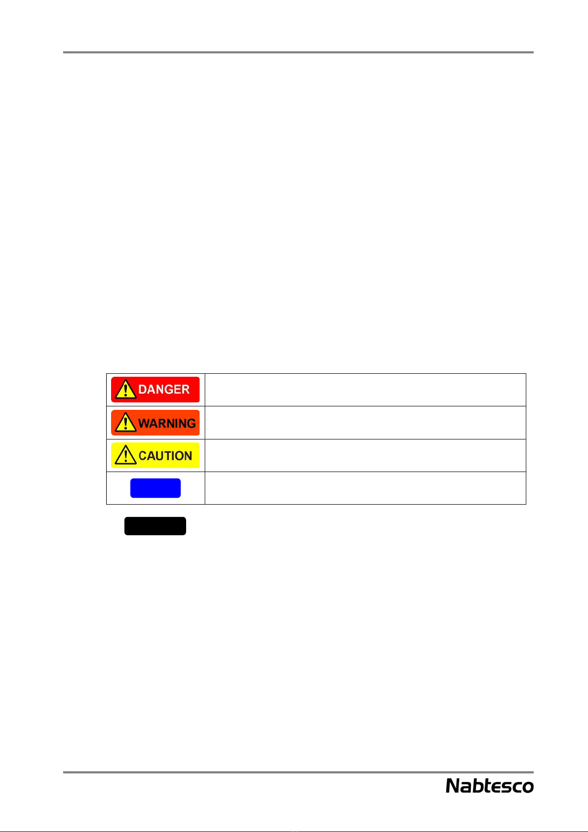
Type and indication of warning.................................................................................................................. 1
1.2.
General precautions.................................................................................................................................... 2
1.3.
Product Overview ........................................................................................ 3
Chapter 2
Name of each section ................................................................................................................................. 3
2.1.
Lubricant .................................................................................................................................................... 4
2.2.
Transportation and Storage of Product ..................................................... 5
Chapter 3
Transportation ............................................................................................................................................ 5
3.1.
Storage ....................................................................................................................................................... 6
3.2.
Preparations for Installation ....................................................................... 7
Chapter 4
Installation environment ............................................................................................................................ 7
4.1.
Preparation of required components .......................................................................................................... 8
4.2.
Unpacking.................................................................................................................................................11
4.3.
Lifting of this product .............................................................................................................................. 13
4.4.
Installation.................................................................................................. 14
Chapter 5
Installation position.................................................................................................................................. 14
5.1.
Bolt tightening torque .............................................................................................................................. 15
5.2.
Installation work ...................................................................................................................................... 15
5.3.
Contents

Contents
Operation.................................................................................................... 25
Chapter 6
Checking before operation....................................................................................................................... 25
6.1.
Running-in operation ............................................................................................................................... 25
6.2.
Precautions for operation ......................................................................................................................... 25
6.3.
Servomotor............................................................................................................................................... 26
6.4.
Maintenance and Inspection..................................................................... 27
Chapter 7
Precautions on maintenance..................................................................................................................... 27
7.1.
Daily inspection ....................................................................................................................................... 27
7.2.
Precautions when handling the lubricant ................................................................................................. 28
7.3.
Lubricant replacement.............................................................................................................................. 29
7.4.
Troubleshooting checksheet..................................................................................................................... 33
7.5.
Contact Information

Important Information
i
1. Intended use of this product
This product was designed and manufactured as a reduction gear that decelerates the rotation of the motor
and transmits the rotational torque. Do not use this product for other purposes.
Do not modify the reduction gear or use it outside its specified range. Failure to do so could cause
injury or damage to the reduction gear.
The specifications indicated in the product catalog are based on Nabtesco evaluation methods. This
product should only be used after confirming that it is appropriate for the operating conditions of
your system. Failure to do so could cause injury or damage to the reduction gear.
2. Rules to ensure safe use of this product
It is impossible for Nabtesco Corporation (referred to as “Nabtesco” hereafter) to foresee any potential
hazards related to this product and hazards caused by human errors or peripheral devices.
There are also various points that must be observed and operations that are prohibited in relation to the use
of this product, but it is also impossible to note all of them in this manual.
For this reason, it is necessary to take appropriate safety measures when operating this product, in addition
to the points noted in this manual.
The particularly important information for safe handling of this product is noted below. This information
applies to all workers involved, including the manager and supervisor of this product.
The “procedures” referred to in this manual indicate all the acts performed on this product during
transportation, installation, operation, and maintenance/inspection.
Be sure to read this manual.
Before using this product, thoroughly read this manual and understand all the content of this manual.
Also, observe the safety precautions described in this manual.
Conditions for workers
• The worker must have a fundamental knowledge of this product
• The worker must be aware of the potential hazards of this product and have adequate knowledge to
avoid hazardous situations
• The worker must be able to take appropriate measures to avoid hazardous situations
Important Information

Important Information
ii
Observe the relevant laws, regulations, ordinances, and bylaws.
Observe the relevant laws, regulations, ordinances, and bylaws enacted by the related countries and
local governments.
Prevention of accidents
• To prevent accidents, do not perform any procedures not noted in this manual. Also, do not use this
product for any purposes other than those noted at the beginning of this manual.
• If any abnormalities are found, take appropriate measures immediately to prevent any accidents,
serious injury, or damage.
• Everyone, including workers and supervisors, must voluntarily take measures to ensure safety and
well-being, as this can prevent accidents.
3. Sharing of hazard information with users
When selling or transferring this product embedded in a device, etc., hand this manual to the person who
actually uses or manages the device (the person/group in charge). Or, add the necessary information
concerning handling and maintenance procedures for preventing the accidents and failures described in
this manual to the contents of the operation manual of the device.
4. Product disposal
When disposing of this product, drain the lubricant completely and handle it according to the ordinances
of the local government and entrust the disposal to an industrial waste disposal specialist.
5. Other important notes
It is strictly prohibited to reverse-engineer the internal parts of this product.

About This Manual
iii
1. Users of this manual
This manual is intended for native speakers of English. If this product is operated by non-native speakers
of English, the customer is responsible for conducting safety training and giving operation instructions to
those workers.
2. Copyrights
The copyright for this manual belongs to Nabtesco Corporation. Unauthorized reprinting, reproduction,
copying, or translation of this manual in whole or in part is strictly prohibited.
About This Manual

Warranty
iv
1. In the case where Nabtesco confirms that a defect of the Product was caused due to
Nabtesco’s design or manufacture within the Warranty Period of the Product,
Nabtesco shall repair or replace such defective Product at its cost. The Warranty
Period shall be from the delivery of the Product by Nabtesco or its distributor to you
(“Customer”) until the end of one (1) year thereafter, or the end of two thousand
(2,000) hours from the initial operation of Customer's equipment incorporating the
Product at end user's production line, whichever comes earlier.
2. Unless otherwise expressly agreed between the parties in writing, the warranty
obligations for the Product shall be limited to the repair or replacement set forth
herein. OTHER THAN AS PROVIDED HEREIN, THERE ARE NO
WARRANTIES ON THE PRODUCT, EXPRESS OR IMPLIED, INCLUDING
WITHOUT LIMITATION ANY IMPLIED WARRANTY OF
MERCHANTABILITY OR FITNESS FOR A PARTICULAR PURPOSE.
3. The warranty obligation under Section 1 above shall not apply if:
a) the defect was caused due to the use of the Product deviated from the Specifications or the
working conditions provided by Nabtesco;
b) the defect was caused due to exposure to foreign substances or contamination (dirt, sand,
etc.)
c) lubricant or spare part other than the ones recommended by Nabtesco was used in the
Product;
d) the Product was used in an unusual environment (such as high temperature, high humidity,
a lot of dust, corrosive/volatile/inflammable gas, pressurized/depressurized air, under
water/liquid or others except for those expressly stated in the Specifications);
e) the Product was disassembled, re-assembled, repaired or modified by anyone other than
Nabtesco;
f ) the defect was caused due to the equipment into which the Product was installed;
g) the defect was caused due to an accident such as fire, earthquake, lightning, flood or others;
or
h) the defect was due to any cause other than the design or manufacturing of the Product.
4. The warranty period for the repaired/replaced Product/part under Section 1 above
shall be the rest of the initial Warranty Period of the defective Product subjected to
such repair/replace.
Warranty

Glossary
v
Rated service life
The lifetime resulting from the operation with the rated torque and the rated output speed is referred to as
the “rated service life”.
Allowable acceleration/deceleration torque
When the machine starts or stops, the load torque to be applied to the reduction gear is larger than the
constant-speed load torque due to the effect of the inertia torque of the rotating part. In such a situation, the
allowable torque during acceleration/deceleration is referred to as “allowable acceleration/deceleration
torque”.
Note: Be careful that the load torque, which is applied at startup and stop, does not exceed the allowable
acceleration/deceleration torque.
Momentary maximum allowable torque
A large torque may be applied to the reduction gear due to execution of emergency stop or by an external
shock. In such a situation, the allowable value of the momentary applied torque is referred to as
“momentary maximum allowable torque”.
Note: Be careful that the momentary excessive torque does not exceed the momentary maximum
allowable torque.
Allowable output speed
The allowable value for the reduction gear’s output speed during operation without a load is referred to as
the “allowable output speed”.
Note: The reduction gear temperature may exceed 60°C even when the speed is under the allowable
speed depending on the operation conditions (duty, load, ambient temperature, etc.). In such a case,
use the reduction gear at the speed so that the gear surface temperature is 60°C or lower.
Allowable moment and maximum thrust load
The external load moment or thrust load may be applied to the reduction gear during normal operation.
The allowable values at this time are referred to as “allowable moment” and “maximum thrust load”
respectively.
Note 1: The above specification values are noted in the catalog or separately provided
specification sheet.
Note 2: The “reduction gear” indicated in this manual refers to the “RS series turn table gearhead”
of the product.
Glossary
Load torque
External shock torque
Max torque for startup
Constant torque
Time
Max. torque
for stop
Shock torque at
emergency stop

Chapter 1 About Safety
1
About Safety
Chapter 1
The safety precautions noted in this chapter should be used as guidelines to prevent injury of workers who
perform transportation, installation, operation, and maintenance of this product, as well as damage to the
product.
About warnings
1.1.
This manual alerts workers to hazardous situations and precautions related to this product in the following
manner:
1. Safety regulations are described in Chapter 1 “About safety” in this manual
2. Warning statements are noted in this manual
Type and indication of warning
1.2.
Warnings for potential hazards during operation are given according to the following four categories in
this manual. If you fail to observe these warning statements, it could result in lethal injury or serious
damage and malfunction of the product.
Indicates a hazardous situation that, if not avoided, is highly likely to result in death or
serious injury.
Indicates a potentially hazardous situation that, if not avoided, could result in death or
serious injury.
Indicates a potentially hazardous situation that, if not avoided, could result in minor or
moderate injury.
Indicates a potentially hazardous situation that, if not avoided, could result in physical
damage.
Provides important information for correct use of this product, as well as supplemental
explanation for the main body of the text or other information that helps to prevent
erroneous operation.
Note
Important

Chapter 1 About Safety
2
General precautions
1.3.
This section describes general precautions for safe use of this product. For precautions concerning
transportation, installation, operation, maintenance, and inspection, be sure to confirm the contents of the
relevant chapter.
Do not modify or disassemble the reduction gear in a manner not described in this manual. Failure
to do so could cause injury or damage to the reduction gear.
Transportation, installation, operation, maintenance, and inspection of the reduction gear must be
performed by personnel who fully understand this manual. The person in charge of the operation
and manager of the reduction gear must not allow anyone without an understanding of the contents
of this manual to operate it. Failure to do so could cause injury or damage to the reduction gear.
Do not put your fingers or any object into the opening of the reduction gear. If a belt or chain is used
for connection of the drive sections, do not put your fingers or any object into the clearance of the
protective cover, etc., as it could cause injury.
If any abnormalities or damage to the reduction gear are found, stop the operation immediately.
Incorrect motion could cause injury.
The reduction gear could become extremely hot during operation. After stopping the operation,
never touch the reduction gear until it is completely cooled. Touching the reduction gear could cause
burns.
Handle the lubricant according to the instructions given in this manual. Failure to do so could impair
your health.
Return the tools and other necessary items to the specified location after use. If a tool, bolt, nut, or
other foreign object is trapped in the system, it could cause damage to the reduction gear.
Avoid excessive impact or vibration of the reduction gear. Failure to do so could cause damage to
the reduction gear.
Note

Chapter 2 Product Overview
3
Product Overview
Chapter 2
This chapter describes an overview of this product.
Name of each section
2.1.
This section provides an explanation of the name of each section.
If the shape of the actual section differs from the illustration below, refer to the separately provided “Outer
dimensions” drawings and specification sheet.
(1) RS-260A
(2) RS-320A
Fig. 2-1
Hole for installing
reduction gear
Tapped hole for installing component
(Tapped hole for hanging bolt)
Installation
reference
surface
(3 locations)
Tapped hole for
injecting/draining
grease
(Component
to be rotated)
Center pipe
(Wiring and hollow hole for wiring)
(Component to be fixed)
Base flange
Tapped hole for installing motor flange
Output flange
Tapped hole
for injecting/draining grease
Fig. 2-2
Tapped hole for hanging bolt
Hole for installing
reduction gear
Tapped hole for installing component
Base flange
Tapped hole for
installing motor flange
Output flange
(Component to be fixed)
Installation
reference surface
(3 locations)
Tapped hole for
injecting/draining grease
(Component to be rotated)
Center pipe
(Wiring and hollow hole
for wiring)
Tapped hole for
injecting/draining grease

Chapter 2 Product Overview
4
(3) RS-900A
The shape of the reduction gear may differ from the illustration depending on the ordered
specifications.
Lubricant
2.2.
• The specified lubricant is filled before shipping.
• When replacing the lubricant, be sure to use the Nabtesco-specified lubricant. For purchase of the
lubricant, contact our service representative.
• Do not mix it with other lubricants.
Table 2-1
Model RS-260A RS-320A, RS-900A
Brand specified by Nabtesco VIGOGREASE* RE0 Molywhite RE No. 00
Operating temperature range
(ambient temperature) -10 to 40°C -10 to 40°C
* VIGOGREASE is registered trademark of Nabtesco Corporation.
In order to take advantage of the performance of this product, use the Nabtesco-specified lubricant.
Using other types of lubricant could cause deterioration of performance and premature damage.
Mixing with other lubricants could cause deterioration of performance, generation of abnormal noise,
and premature damage.
Important
Note
Fig. 2-3
Hole for installing reduction gear
Tapped hole for installing component
Installation
reference
surface
(3 locations)
Tapped hole for
injecting/draining
grease
(Component to be
rotated)
Center pipe
(Wiring and hollow hole
for piping)
(Component to be fixed)
Tapped hole for installing motor
flange
Base flange
Output flange
(Tapped hole for
hanging bolt)
Tapped hole for
injecting/draining
grease

Chapter 3 Transportation and Storage of Product
5
Transportation and Storage of Product
Chapter 3
This chapter describes the transportation and storage of this product.
Transportation
3.1.
• Refer to the weights of the reduction gears listed in Table 3-1 and transport the product in an
appropriate way.
• If the reduction gear needs to be lifted after unpacking, also refer to “4.4 Lifting of this product”.
• Do not stack the packing boxes containing the reduction gear too high.
• Avoid excessive impact or vibration of the reduction gear.
Table 3-1
Model Weight (kg)
RS-260A 165
RS-320A 290
RS-900A 480
If the packing boxes containing the reduction gear are stacked too high during transportation, they
may collapse and fall down, causing injury or damage to the reduction gear.
Applying excessive impact or vibration to the reduction gear could cause damage to the reduction
gear.
The weight shown in Table 3-1 indicates the weight of the reduction gear only. The weight of the
packing box, motor flange, input spline, etc. is not included.
The actual weight of the reduction gear may slightly differ from that listed in the above table,
depending on the specifications.
Note
Important

Chapter 3 Transportation and Storage of Product
6
Storage
3.2.
To avoid rust, corrosion, or deterioration of the sealing material, etc., and collapse of stored packing boxes,
store the product in the following location.
• Location where the ambient temperature is between -10°C to 40℃.
• Location where the humidity is less than 85% and no condensation occurs
• Location that is not directly affected by wind and rain
• Location that is free from combustible/volatile/corrosive gas or dust.
• Stable location that is free from any danger of collapse
• Location with little vibration
When storing the reduction gears, do not stack too many packing boxes. They may collapse and fall
down, causing injury or damage to the reduction gear.
Store the reduction gear under the same conditions as those before unpacking. If it is left upside
down, it could cause damage to the reduction gear.
Although the reduction gear is coated with rust prevention oil before shipping, it is not designed for
long-term storage. If it is stored for a long period, check the condition of the reduction gear
periodically and perform rust prevention treatment as necessary. If rust occurs, it could cause the
leakage of lubricant or premature damage to the reduction gear.
If the reduction gear is used or operated after it has not been used for a long period of time, confirm
that it is free from rust or corrosion and that the sealing material is free from deformation or cracks
beforehand. If the reduction gear is used without checking these points, it could cause the leakage
of lubricant or premature damage to the reduction gear.
Note

Chapter 4 Preparations for Installation
7
Preparations for Installation
Chapter 4
This chapter describes the preparation for installing this product.
Before designing the equipment, take care regarding the following precautions.
• When the reduction gear is used for human transportation equipment or rotary equipment, install an
effective safety unit as a fail-safe mechanism, in case of an unexpected failure in the reduction gear.
• When the reduction gear is used for elevating equipment, install an effective safety unit for
preventing falls caused by idle running as a fail-safe mechanism, in case of an unexpected failure in
the reduction gear.
• Install an oil receiver, etc., to prevent damage in case of lubricant leakage due to a failure or lifetime
expiration.
• As this product may have residual rust prevention agent coated on it before shipping, wipe it off as
necessary.
When the reduction gear is used for human transportation equipment or rotary equipment, install an
effective safety unit as a fail-safe mechanism, in case of an unexpected failure in the reduction gear.
If you fail to install it, it could cause injury in case the equipment goes out of control or falls off.
When the reduction gear is used for elevating equipment, install an effective safety unit for
preventing falls caused by idle running as a fail-safe mechanism, in case of an unexpected failure in
the reduction gear. If you fail to install it, it could cause injury in case the elevating unit falls off.
Installation environment
4.1.
Use this product under the following environment:
• Location where the ambient temperature is between -10°C to 40℃.
• Location where the humidity is less than 85% and no condensation occurs
• Location where the altitude is less than 1,000 m
• Well-ventilated location
Do not install the reduction gear at the following locations.
• Location where a lot of dust is collected
• Outdoors that can be directly affected by wind and rain
• Location near the environment that contains combustible/explosive/corrosive gases and flammable
materials
• Location where the magnetic fields or vibration occur
When operating the reduction gear in a location where there is a lot of dust or particles, or where machine
oil or water, etc. can enter, attach the protective cover to protect the oil seal on the output shaft. (When
attaching the protective cover, use the tapped holes on the center pipe.)

Chapter 4 Preparations for Installation
8
Be sure that no load is applied to the center pipe when attaching the protective cover. The oil seals
for the output shaft may be deformed, which could eventually cause leakage of the lubricant.
If the reduction gear is operated without the protective cover under the above conditions, lubricant
may leak from the oil seal on the output shaft.
If the required installation environment cannot be established/met, contact us in advance.
When using this product under special conditions (clean room, equipment for food, medical
equipment, concentrated alkali, high-pressure steam, etc.), contact our service representative in
advance.
Preparation of required components
4.2.
• The following components and materials are required for installing this product. Check the
components/materials and prepare them at each customer’s site.
• If the shape of the actual section differs from the illustration below, refer to the separately provided
“Outer dimensions” drawings and specification sheet.
• Prepare the components on the fixed side and the rotation side, which have been designed and
manufactured either based on the catalog or based on separately provided “Outer dimensions”
drawings and a specification sheet.
The actual components may differ from the required components shown in the above illustration,
depending on the customer’s equipment.
Important
Important Fig. 4-1
Cap (accessory)
(RS-260A only)
Motor flange (accessory)
Hexagon socket head cap screw
(accessory)
Hexagon socket
head cap screw
Serrated lock
washer
Component on
rotation side
O-ring (accessory)
(RS-260A only)
Motor
Motor mounting bolt
Input spline (accessory)
Positioning pin for component on
fixed side
Tapped hole for
injecting/draining grease
Hexagon socket head
cap screw
Serrated lock
washer
Component on
fixed side

Chapter 4 Preparations for Installation
9
Installation components4.2.1.
The customer is required to prepare the following components used for incorporating the reduction gear
into the customer’s equipment.
(Component on fixed side)
• Prepare the installation component on the fixed side to be used for the base flange of the reduction
gear.
Confirm that the design of the prepared component on the fixed side conforms to the size and
quantity of the mounting bolts for the base flange indicated in the catalog and in the separately
provided “Outer dimensions” drawings and specification sheet.
Use the positioning pin or positioning plate when aligning the component on the fixed side with the
reduction gear.
(Component on rotation side)
Prepare the installation component on the rotation side to be attached to the output shaft of the reduction
gear.
Confirm that the design of the prepared component on the rotation side conforms to the size and
quantity of the mounting bolts for the output flange indicated in the catalog and in the separately
provided “Outer dimensions” drawings and specification sheet.
When preparing the component on the rotation side, take extra care not to cover the tapped holes
for injecting/draining grease. If the tapped holes are covered, it will be difficult to replace the
lubricant.
Reduction gear mounting bolts
4.2.2.
• Refer to the size and quantity of the bolts listed in Table 4-1 and Table 4-2.
• Select the appropriate bolt length based on the mounting dimensions of the components prepared by
the customer and the reduction gear.
• Prepare the following bolts recommended by Nabtesco:
Hexagon socket head cap screw JIS B 1176 : 2006
Strength class JIS B 1051 : 2000 12.9
Thread JIS B 0209 : 2001 6g

Chapter 4 Preparations for Installation
10
Component on fixed side Component on rotation side
Table 4-1 Table 4-2
Model Nominal size × pitch
(mm)
Required
Qty. Model Nominal size × pitch
(mm)
Required
Qty.
RS-260A M16 × 2.0 8 RS-260A M12 × 1.75 16
RS-320A M20 × 2.5 8 RS-320A M12 × 1.75 16
RS-900A M20 × 2.5 12 RS-900A M16 × 2.0 27
Serrated lock washer for hexagon socket head cap screw
4.2.3.
Prepare the following serrated lock washer for a hexagon socket head cap screw recommended by
Nabtesco:
Name: Belleville spring washer (made by Heiwa Hatsujyo Industry Co., Ltd.)
Corporation symbol: CDW-H,
CDW-L (Only for M5)
Material: S50C to S70C
Hardness: HRC40 to 48
Table 4-3 (Unit: mm)
Nominal
size
ID and OD of Belleville
spring washer t H
ø
d
ø
D
5 5.25 8.5 0.6 0.85
6 6.4 10 1.0 1.25
8 8.4 13 1.2 1.55
10 10.6 16 1.5 1.9
12 12.6 18 1.8 2.2
14 14.6 21 2.0 2.5
16 16.9 24 2.3 2.8
20 20.9 30 2.8 3.55
When using any equivalent washer, pay particular attention to its outside diameter (ø D) and to the
strength of the spring washer.
Liquid sealant
4.2.4.
When using a liquid sealant to seal the sections between the reduction gear and the motor flange and
between the motor flange and the motor installation surface, prepare one of the following liquid sealants
recommended by Nabtesco.
Table 4-4
Name Manufacturer Characteristics and applications
ThreeBond 1211 ThreeBond • Silicone-based, solventless type
• Semi-dry gasket
HermeSeal SS-60F Nihon Hermetics Co.
• One-part, non-solvent elastic sealant
• Metal contact surface (flange surface) seal
• Any product basically equivalent to
ThreeBond 1211
Loctite 515 Henkel • Anaerobic flange sealant
• Metal contact surface (flange surface) seal
Important
Fig. 4-2
Assemble the bolt so that the
bolt head faces this side

Chapter 4 Preparations for Installation
11
Do not use the above liquid sealants if the component of the customer’s device is made of copper or
copper alloy.
Unpacking
4.3.
Check the following points when unpacking.
• Before using this product, check the contents of the packing box and confirm that all the ordered
items are included.
• Check the top and bottom direction of the packing box and unpack it.
When transporting the reduction gear, take extra care so that it will not fall down or topple over. It
could cause injury to the workers or damage to the reduction gear.
Before using this product, check the contents of the packing box and confirm that all the ordered
items are included. If an incorrect part is installed, it could cause injury to the workers or damage the
customer’s device and the reduction gear.
If it is left upside down, it could cause damage to the reduction gear. (Refer to Fig. 4-3 for the
direction.)
The reduction gear is coated with rust prevention oil before shipping. Therefore, if it is used as it is,
the rust prevention oil could ooze from the bolt hole or flange mating face during operation. In
addition, the rust prevention oil makes the reduction gear slippery. Wipe it off as necessary before
use.
Note
Note
Important

Chapter 4 Preparations for Installation
12
Fig. 4-5
Model
Serial No.
Company logo
QR code
(Reading this QR code will display our
Website URL and the serial number.)
Logo of Precision Reduction Gear RV
Checking the contents
4.3.1.
• Check the shipping label to confirm that it matches the product you have ordered.
• Confirm that the contents of the packing box match the items in the illustration below when
unpacking.
• The packing material may differ depending on the product. The following illustration should only be
referred to as an example.
When inquiring about this product, the model, parts name, and S/N (serial number) indicated on the
shipping label are needed. Write them down when unpacking and keep them for cases in which they
are needed. (The model and serial number indicated on the label may be used.)
The contents of the packing box and shape of the reduction gear may differ from the illustration
above depending on the ordered specifications. The motor flange and input spline may not be
included in the packing box.
Label indication
4.3.2.
A label is attached to the main unit of this product.
Important
Reduction gear
main unit
Input
spline
Motor flange
Hexagon socket head
cap screws (4 screws)
for mounting the motor
flange
Provided with
the main unit of
RS-260A only.
O-ring
Cap
Fig. 4-4
Cautions to the
reduction gear when it
is installed
Accessories
Partition
RS unit
Base
Fig. 4-3
MadeinJapan
NabtescoCorporation
型式RS−320A−170
品目 P67WA001B00
S/NR320-0810001
インプットギヤ
Example Top
Bottom Shipping label
This manual suits for next models
3
Table of contents
Other Nabtesco Industrial Equipment manuals
Popular Industrial Equipment manuals by other brands

Bentone
Bentone BF 1 FUV FAME Installation and maintenance instruction

Lily Corporation
Lily Corporation CD85 Operation and service manual

Tsubaki
Tsubaki EW Series instruction manual

EVAPCO
EVAPCO EAFWD Additional Installation, Operation and Maintenance Instructions

KTR
KTR DATAFLEX 85 Series Operating & assembly instructions

Moog
Moog GAT Rotostat Series operating instructions