9 TAPE 2 IN/OUT: Connections for analog recording and playback to
a tape recorder of any type. Using twin RCA-to-RCA leads, connect
the left and right “Audio Output” of the tape recorder to the TAPE 2 IN
sockets for playback. Connect the left and right “Audio Input” of the tape
recorder to the TAPE 2 OUT sockets for recording.
10 TAPE MONITOR IN/OUT: Connections for analog recording and
playback to a secondary tape recorder of any type. Using twin
RCA-to-RCA leads, connect the left and right “Audio Output” of the
tape recorder to the TAPE MONITOR IN sockets for playback and
tape monitoring. Connect the left and right “Audio Input” of the tape
recorder to the TAPE MONITOR OUT sockets for recording.
TO MAKE A RECORDING
When any source is selected, its signal is also fed directly to any tape
recorder connected to the TAPE 2 OUT or TAPE MONITOR OUT for
recording.
TAPE TO TAPE COPYING
You can copy between two tape recorders connected to your C 356BEE.
Put the source tape in the recorder connected to TAPE 2 and the blank
tape into the recorder connected to TAPE MONITOR. By selecting TAPE2
input you can now record from TAPE 2 to TAPE MONITOR and monitor
the signal coming from the original tape.
NOTE
There will be no TAPE 2 output when TAPE 2 is the selected source input.
This prevents feedback through the recording component thereby
preventing possible damage to your speakers. The same applies to TAPE
MONITOR IN/OUT.
11 PRE OUT 1: The PRE OUT 1 sockets can be used to drive an additional
power amplier. Use a twin RCA-to-RCA lead to connect the left and
right “Audio Input” of the Power amplier or processor to the PRE OUT 1
sockets.
Always turn the C 356BEE and associated external power ampliers OFF
before connecting or disconnecting anything to the PRE OUT 1 sockets.
The PRE OUT 1 output signal will be aected by the C 356BEE’s volume
and tone control settings.
12 PRE OUT 2: Connections to an external power amplier or processor,
such as a surround-sound decoder. In normal use, this should be
connected to the MAIN IN sockets with the links supplied. To connect
your C 356BEE to an external processor or amplier, remove rst these
links. Use a twin RCA-to-RCA lead to connect the left and right “Audio
Input” of a power amplier or processor to the PRE OUT 2 sockets.
Always turn the C 356BEE and associated external power ampliers OFF
before connecting or disconnecting anything to the PRE OUT 2 sockets.
The PRE OUT 2 output signal will be aected by the C 356BEE’s volume
and tone control settings.
13 MAIN IN: Connections to an external preamplier or processor, such as
a surround sound decoder. In normal use, this should be connected to
PRE OUT 2 sockets with the links supplied. To connect your C 356BEE to
an external processor or preamplier, remove rst these links. Use a twin
RCA-to-RCA lead to connect the left and right “Audio Output” of the
preamplier or processor to the MAIN IN sockets.
Always turn the C 356BEE and associated external preampliers OFF
before connecting or disconnecting anything to the MAIN IN sockets.
14 SOFT CLIPPING™: Enables NAD’s proprietary Soft Clipping circuitry
on all channels. At [ON] position, Soft Clipping gently limits the output
of the C 356BEE to minimize audible distortion should the amplier be
over driven. Soft Clipping may simply be left ON at all times to reduce
the likelihood of audible distortion from excessive volume settings.
However, for critical listening and to preserve optimum dynamics, you
may wish to defeat it by setting this switch to “OFF” position.
The SOFT CLIPPING indicator on the front panel will illuminate when the
C 356BEE is in Soft Clipping mode. Refer also to the item below about
“POWERDRIVE”.
POWERDRIVE
The C 356BEE uses NAD’s proprietary PowerDrive™ amplier technology
that provides high dynamic power and low impedance drive capability.
By adding a second high-voltage rail to our well regulated high-
current power supply, we get an “overdrive” that can nearly double the
continuous power on a short term dynamic power basis. This uniquely
ecient power supply topology provides the real world benets of
high dynamic power that remains uncompromised by low impedance
speakers.
15 SPEAKERS A, B: The C 356BEE is equipped with two sets of speaker
connectors. Use the SPEAKERS A terminals for the “main” speakers and
use the SPEAKERS B terminals for a second pair, for example, extension
speakers located in another room.
Connect the right speaker to the terminals marked “R +” and “R-”
ensuring that the “R+” is connected to the “+” terminal on your
loudspeaker and the “R-” is connected to the loudspeaker’s “-” terminal.
Connect the terminals marked “L+” and “L-” to the left speaker in the
same way.
Always use heavy duty (16 gauge; 1.5mm2 or thicker) stranded wire to
connect loudspeakers to your C 356BEE. The high-current binding post
terminals can be used as a screw terminal for cables terminating in
spade or pin sockets or for cables with bare wire ends.
16 SWITCHED AC OUTLET (120V version only): This convenience outlet
can supply switched power to another component or accessory. With
the POWER switch at the rear panel set to ON position, this outlet is
powered ON or OFF by the front panel STANDBY switch or by the SR 8’s
[ON/OFF] buttons. The total draw of all devices connected to this outlet
must not exceed 120 watts.
17 AC MAINS INPUT: The C 356BEE comes supplied with a separate
detachable mains power cord. Before connecting the plug to the mains
power source, ensure that it is rmly connected to the C 356BEE’s AC
Mains input socket rst. Connect only to the prescribed AC outlet,
i.e., 120V 60 Hz (for 120V version models of C 356BEE only) or 230V
50 Hz (for 230V version models of C 356BEE only). Always disconnect
the mains power plug from the mains power source rst, before
disconnecting the cable from the C 356BEE’s AC Mains input socket.
18 POWER SWITCH: The POWER switch supplies the master mains power
for the C 356BEE. When this switch is at ON position, the C 356BEE
is in standby mode as shown by the amber status condition of the
standby LED. Toggle the front panel’s STANDBY button to switch ON the
C 356BEE or back to standby mode. Switch o the POWER switch if you
intend not to use the C 356BEE for long periods of time (such as when
on vacation). It is not possible to switch ON the C 356BEE using the
front panel STANDBY button or SR 8 remote control’s [ON] button if the
rear panel POWER switch is switched o.
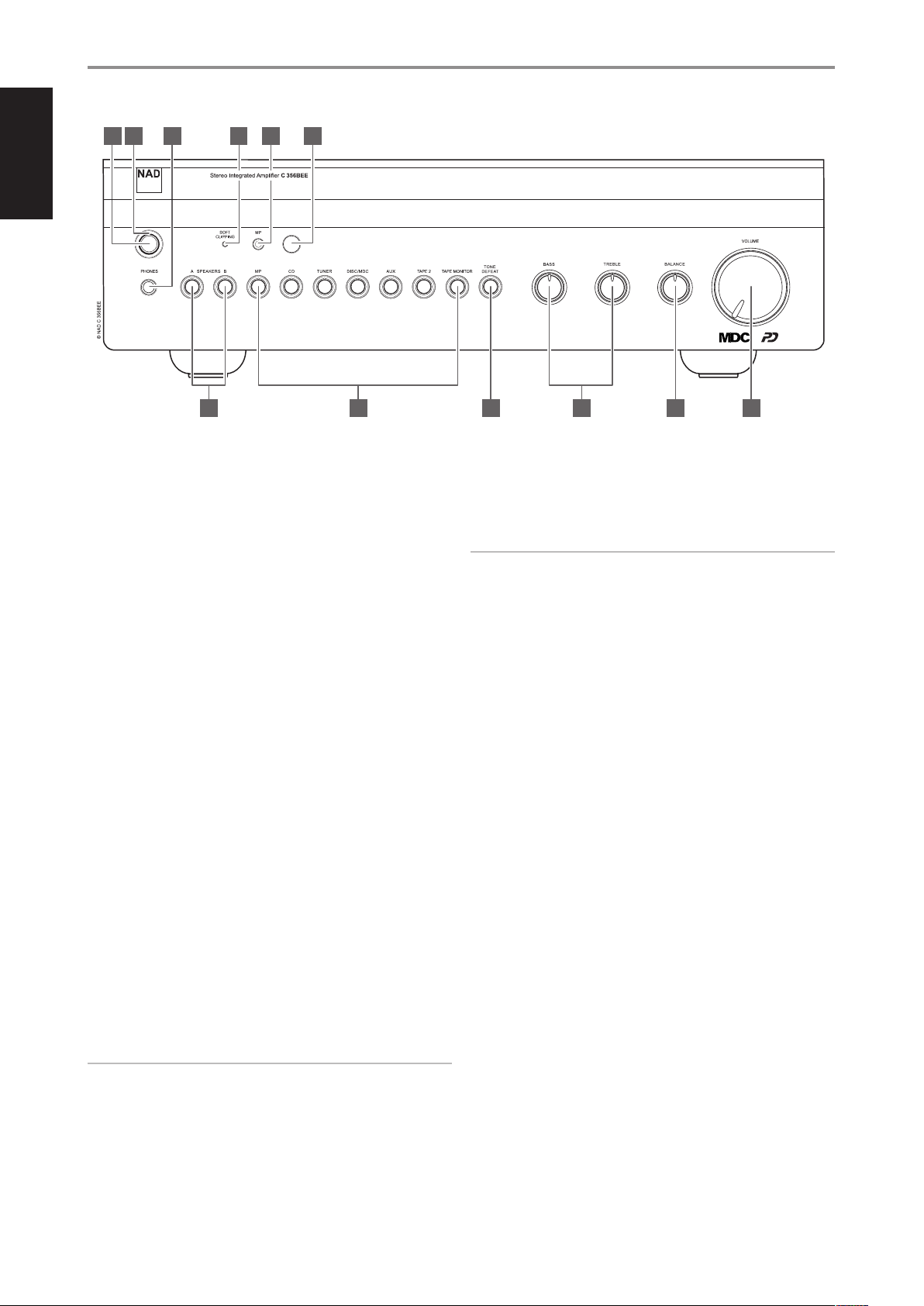
IDENTIFICATION OF CONTROLS
REAR PANEL
9
ENGLISHFRANÇAISESPAÑOLITALIANODEUTSCHNEDERLANDSSVENSKAРУССКИЙ