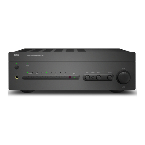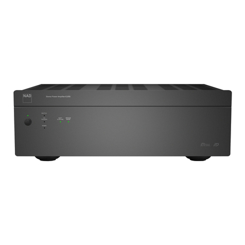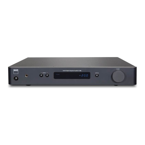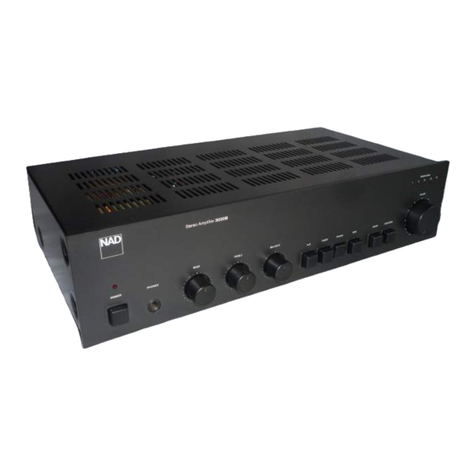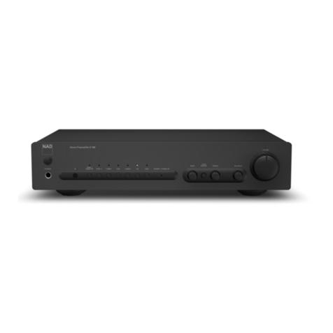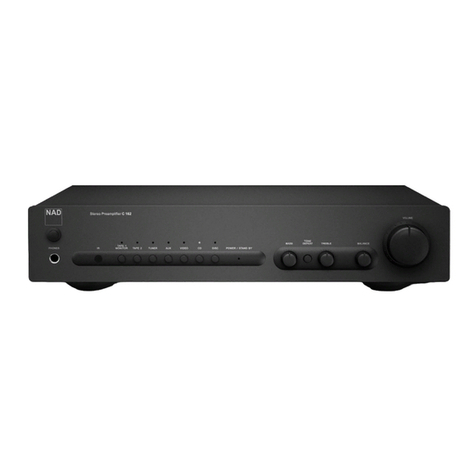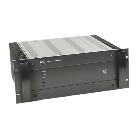
CONTENTS
FRONT PANEL / REAR PANEL VIEW................................... 3
SPECIFICATIONS................................................... 4
EXPLODED VIEW.................................................. 29
EXPLODED VIEW PARTS LIST ....................................... 30
PACKING DIAGRAM................................................ 31
ALIGNMENT PROCEDURE / ALIGNMENT POINTS........................ 5
WIRING DIAGRAM.................................................. 6
PCB LAYOUT ................................................... 7-12
SCHEMATIC DIAGRAM............................................13-21
IC BLOCK DIAGRAM................................................22
ELECTRICAL PARTS LIST .........................................23-28
SERVICE SAFETY PRECAUTIONS
1. ReplacingtheFuses
2. Safety-checkout (NorthAmericanmodelonly)
CAUTION:
NOTE:
FOR CONTINUED PROTECTIONAGAINST THE RISK OF FIRE REPLACE ONLY
WITHSAMETYPEOFFUSE.
Parts marked with the symbol are critical with regard to the risk of fire and electric shock.
Replaceonlywithpartsrecommendedbythemanufacturer.
Beforereturningtheproducttothecustomer, makeleakagecurrent orresistancemeasurements
todeterminethatexposedpartsareacceptablyinsulatedfromthesupplycircuit.
REFERENCENO. PARTNUMBER DESCRIPTION
F1*AH 5100-2510-1C Fuse 250mA250VTimeLagUL/CSA
F2*AH 5120-0061-0 Fuse12A250VTimeLag6.3x32mm UL/CSA
F1*C 5120-0035-0 Fuse100mA250VTimeLagLBCVDE/SEMKO
F2*C 5120-0025-0 Fuse6.3A250VTimeLagHBCVDE/SEMKO
*AH:NorthAmericanmodelonly
*C :Europeanmodelonly
!
2

