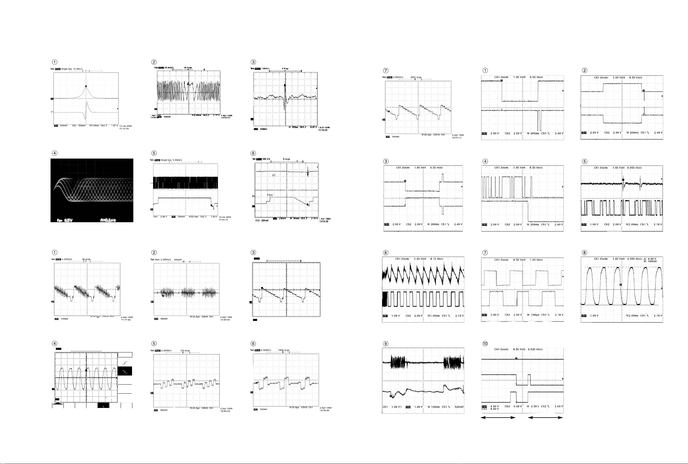
NAD T571C User manual

SERVICE MANUAL
SERVICE MANUAL
T571C
T571AH
DVD VIDEO PLAYER
T571C
T571AH
DVD VIDEO PLAYER
T571C
T571AH
DVD VIDEO PLAYER
MODELS : T571C/T571AHSERVICE MANUAL
© NAD 2001
NAD ELECTRONICS INTERNATIONAL
TORONTO

NOTES) Warning
NOTES) Parts that are shaded are critical
NOTES) With respect to risk of fire or
NOTES) electricial shock.
470µF/2.3V
'01. 09. 21 R10581B
T571C/T571AH
3-17 3-18
CIRCUIT DIAGRAM
1. POWER(SMPS) CIRCUIT DIAGRAM
NOTE :
1. Shaded( ) parts are critical for safety. Replace only
with specified part number.
2. Voltages are DC-measured with a digital voltmeter
during Play mode.
Oscillation abnormal
Digitron no Power
3.3V line dead.
No Power
8V line dead
5V_A/5V_D, No Power
No Power

3-19 3-20
5
56
Spindle Servo Loop
RF SIGNAL
Focus Servo Loop
Tracking Servo Loop
Sled Servo Loop
WAVEFORM
T571C/T571AH
2. DVD DSP CIRCUIT DIAGRAM
DVD/CD picture
audio abnormal
MPEG Interface
Line
µ-com
Interface Data µ-com
Interface adress
CD/DVD picture
audio abnormal
Tracking/Focus
Servo fail
Tracking
Servo fail
Spindle Motor
abnormal
CD/DVD picture
audio abnormal
Focus Servo
fail
Tracking
Servo fail
Scratched
Disc abnormal
Sled Servo fail
DRAM Control
Disc Detect
Error
Spindle Servo fail

3-21 3-22
3. DRIVE & RF CIRCUIT DIAGRAM
4
1
6
2
3
1
WAVEFORM
Spindle Servo Loop
Turn Table Loop
Focus Servo Loop
Tracking Servo Loop
Sled Servo Loop
T571C/T571AH
Turntable
not operate
Tray Loading
Speed control
Turn table
speed control
Spindle Motor
unstable Actuator spindle
sled not operate
DVD laser
not operate
CD laser
not operate
Servo fail
DVD Mode fail DVD
Laser not operate
Tracking Servo fail
Focus
Servo fail
µ-com
Interface line
CD/DVD picture
abnormal

4
43752 6
WAVEFORM
OPTICAL/COAXITAL OUT
Y/Pb/Pr(Component)
Y.c(S-VHS)
Audio L/R OUT
CVBS
T571C/T571AH
3-23 3-24
4. PANTERA CIRCUIT DIAGRAM
No Power on
Audio DAC Interface
System not operate
DSP interface line
Spindle Motor
unstable
System not working or
Digitron not display.

3-25 3-26
• WAVEFORMS
IC2A1 Pin 42, Focus Error
IC2A1 Pin 36, Pi
IC2A1 Pin 41
Tracking Error IC501 Pin 114
Component Y
IC2A1 Pin 41
VBR TRACKING Error
IC2A1 Pin 57,
RF
IC201 Pin 88, SLED Drive(FMO)
IC201 Pin 18, SLED FG
IC2A1 Pin42, Focus Error(in Focus Search)
IC201 Pin 83, Focus Drive(FDO)
IC501 Pin 118, Composite IC501 Pin 112, Chrominance
(Super video out Mode)
Tek Stop : 2.50MS/s 4 Acqs
M20.0µs2 Apr 1999
14:47:27
Glitch Ch1
Ch3 500mV
[T ]
T
3
IC501 Pin 114, Luminance
(Super video out Mode)
Tek Stop : 1 00kS/s 3290 Acqs
M 500µsCH1 280/mV
Edge Slope
Type
<Edge>
Source
Ch1
Coupling
DC
Level
280mV
Mode
&
Holdoff
3
Ch3 1.00V
[ T ][ T ]
Slope
T
IC501 Pin 99,
PANTER MAIN
IC501 Pin 112
Component Pb
IC501 Pin 110
Component Pr
TURN(+)(-) from Motor Drive
Reverse turn
Sensor 1 (disc position)
Sensor 2 (disc ready)
TURN(+)(-) Signal from µ-com
TE/TZC After tracking
servo ON (Play mode)
TURN(+)(-) from Motor Drive
Forward turn
TE/TZC Before tracking
servo ON
TZC/MIRR (Search mode) FG Signal from M/D
(Play mode)
TE/SLD(+) Search mode
(outter &inner) Tray open Tray closed

3-27 3-28
5. MEMORY CIRCUIT DIAGRAM
T571C/T571AH
Program download fail
Digitron abnormal
Not used
Not power on
Not memoried
setup Menu
Turntable not operating
“No Disc” display
Tray not open/close
Tray not closed
Pick-up not initial
operating
Disc Detec Error
Disc number
detect error
Digitron all not display and
system not operate
Digitron all not display
System not working
Digitron all not display
System not working

3-29 3-30
6. TIMER & KEY CIRCUIT DIAGRAM
T571C/T571AH
System not
operate
Remocon
not operate
Power not
control
Digitron
abnormal
Digitron
abnormal

3-31 3-32
7. A/V CIRCUIT DIAGRAM
L
R
T571C/T571AH
Q401 is defective 2CH.
Audio out bad.
IC401 is defective.
2CH Audio out bad.
IC401 is defective.
2CH Audio out bad.
IC403, Q404 are defective.
Digital data out bad.

3-33 3-34
8. A/V JACK CIRCUIT DIAGRAM (T571AH ONLY)
T571C/T571AH
Component, S-Video out
can,t be changed.

3-35 3-36
9. SCART CIRCUIT DIAGRAM (T571C ONLY)
T571C/T571AH
Component, S-Video out
can,t be changed.

3-37 3-38
LEVEL(V)
MODE
PIN NO.
1
2
3
4
5
6
7
8
9
10
11
12
13
14
15
16
17
18
19
20
21
22
23
24
25
26
27
28
29
30
31
32
33
34
35
36
37
38
39
40
41
42
43
44
45
46
47
48
49
50
51
52
53
3.18
1.3
1.4
2.2
1.5
0
1.5
1.4
1.6
3.1
0.7
0.15
0.15
0
0
1.7
1.4
0
1.5
1.6
0
1.6
0
3.1
1.7
1.4
3.1
1.5
0.15
0
0.7
1.5
2.2
2
3.1
2.9
2.2
2.9
0
0
0
1.6
3.1
1.6
1.5
0
1.4
0
1.5
1.7
1.2
3.1
LEVEL(V)
MODE
PIN NO.
54
55
56
57
58
59
60
61
62
63
64
65
66
67
68
69
70
71
72
73
74
75
76
77
78
79
80
81
82
83
84
85
86
87
88
89
90
91
92
93
94
95
96
97
98
99
100
101
102
103
104
105
106
107
108
1.6
1.4
1.5
0
1.6
1.4
1.5
1.4
3.1
1
1.5
0.005
0.5
0.003
1.58
0
3.1
1.2
1.2
1.2
1.2
3.1
1.65
2.2
1.5
1.5
3.1
3.1
0.001
3.1
3.7
0
3.1
3.1
2.1
0.004
3.1
0
0
0
2.1
3.1
0
0
0
0
2.1
2.1
LEVEL(V)
MODE
PIN NO.
109
110
111
112
113
114
115
116
117
118
119
120
121
122
123
124
125
126
127
128
129
130
131
132
133
134
135
136
137
138
139
140
141
142
143
144
145
146
147
148
149
150
151
152
153
154
155
156
157
158
159
160
161
162
163
0
0.8
0.9
1.3
3.1
0.78
0
1.26
2.38
0.08
1.2
2
0
3.1
3.1
3.1
3.1
0
2.2
3.1
3.1
3.1
3.1
3.1
3.1
3.1
3.1
3.1
3.1
0
3.1
3.1
3.1
3.1
3.1
3.1
3.1
3.1
3.1
3.1
3.1
2.2
1.5
3.1
0
LEVEL(V)
MODE
PIN NO.
164
165
166
167
168
169
170
171
172
173
174
175
176
177
178
179
180
181
182
183
184
185
186
187
188
189
190
191
192
193
194
195
196
197
198
199
200
201
202
203
204
205
206
207
208
209
210
211
212
213
214
215
216
217
218
3.1
3.1
3.1
3.1
3.1
3.1
3.1
0
3.1
3.1
3.1
1.5
3.1
0
3.1
3.1
3.1
3.1
3.18
0.086
3
2.4
2.3
0
0
3.1
0
0.017
2.2
3.1
3.1
0
3.18
1.3
3.1
3.1
3.1
0
2.3
3.1
0.001
3.1
3.1
3.1
1.6
3.1
3.18
0.018
2.2
3.19
2.69
1.5
2.9
2.59
0
LEVEL(V)
MODE
PIN NO.
219
220
221
222
223
224
225
226
227
228
229
230
231
232
233
234
235
236
237
238
239
240
2.29
2.08
2.29
2.29
2.49
3.1
2.39
2.45
1.5
0
1.52
0
1.61
1.6
3.1
1.6
1.6
1.5
0
1.6
1.4
1.5
LEVEL(V)
MODE
PIN NO.
1
2
3
4
5
6
7
8
9
10
11
12
13
14
15
16
17
18
19
20
21
22
23
24
25
26
27
28
29
30
31
32
33
34
35
36
37
38
39
40
41
42
43
44
45
46
47
48
49
50
51
52
53
4.3
3.1
0
3.2
2
3.1
0.01
3.1
3.2
3.2
3.2
3.2
0
3.1
3.1
3.1
0
0
0
3
0.625
3.2
0.705
3.2
3.1
0
3.1
3.1
2.39
3.2
1.49
1.5
3.09
1.69
0
3.1
3.1
2.5
3.1
3.1
3.2
3.1
3.1
LEVEL(V)
MODE
PIN NO.
54
55
56
57
58
59
60
61
62
63
64
65
66
67
68
69
70
71
72
73
74
75
76
77
78
79
80
81
82
83
84
85
86
87
88
89
90
91
92
93
94
95
96
97
98
99
100
3.1
3.1
3.1
3.1
3.1
3.1
3.1
0.5
0
3.1
3.1
3.1
3.1
3.1
1.6
0
0
3.1
0
3.1
0
3.2
0
3.1
0.3
0
0
2.5
0
3.19
3.19
4.4
3.19
4.4
0
4.4
0
0
0
0
0
3.17
3.17
3.1
0
PANTERA MEMORY
IC301IC501
EE PLAY
MODE
PIN NO.
DSP
IC201 SP3301
1
2
3
4
5
6
7
8
9
10
11
12
13
14
15
16
17
18
19
20
21
22
23
24
25
26
27
28
29
30
31
32
33
34
35
36
37
38
39
40
41
42
43
44
45
46
47
48
49
50
51
52
53
2.00
2.00
2.00
2.00
2.00
2.00
2.00
2.00
2.00
2.00
2.00
2.00
2.00
2.00
2.00
2.00
0.00
0.00
0.00
0.00
0.00
3.10
0.00
0.00
0.00
0.00
0.00
2.10
0.00
2.10
3.10
3.10
3.10
3.10
2.10
1.10
0.00
0.00
0.00
3.10
0.00
3.10
0.00
0.00
3.10
0.00
0.00
0.00
0.00
0.00
0.00
3.10
0.00
1.30
1.30
1.30
1.30
1.30
1.30
1.30
1.30
1.30
1.30
1.30
1.30
1.30
1.30
1.30
1.30
0.00
1.50
1.50
1.50
1.50
3.00
1.50
1.50
1.50
1.50
1.50
1.50
0.00
2.00
3.00
1.50
2.50
2.50
1.30
1.80
0.00
0.00
0.00
3.00
0.00
3.00
0.00
0.00
3.00
0.00
0.00
0.00
3.00
0.00
0.00
1.80
0.00
EE PLAY
MODE
PIN NO.
54
55
56
57
58
59
60
61
62
63
64
65
66
67
68
69
70
71
72
73
74
75
76
77
78
79
80
81
82
83
84
85
86
87
88
89
90
91
92
93
94
95
96
97
98
99
100
101
102
103
104
105
106
107
108
3.10
3.10
0.00
0.00
5.00
0.00
0.00
5.00
0.00
2.10
0.00
3.10
0.00
3.10
0.00
0.00
0.00
3.10
0.00
0.00
3.10
0.00
0.00
0.00
0.00
3.10
5.00
0.00
5.00
2.10
2.10
3.10
1.40
0.00
2.10
2.10
0.00
1.50
3.10
1.60
1.10
2.00
1.55
0.00
1.55
1.56
3.10
1.55
1.55
1.62
1.55
1.50
0.00
0.00
0.00
3.00
3.00
0.00
3.13
4.98
0.00
0.00
4.98
0.00
2.10
0.00
3.00
0.00
3.12
0.00
0.20
0.00
3.10
0.20
0.00
3.10
0.00
0.00
0.00
2.30
3.10
5.00
0.00
5.00
2.00
2.10
3.10
1.40
0.00
2.00
2.00
0.00
1.55
3.12
1.55
1.11
2.00
1.55
0.00
1.55
2.15
3.10
1.58
1.55
1.64
1.55
1.50
0.00
0.00
0.00
EE PLAY
MODE
PIN NO.
109
110
111
112
113
114
115
116
117
118
119
120
121
122
123
124
125
126
127
128
129
130
131
132
133
134
135
136
137
138
139
140
141
142
143
144
145
146
147
148
149
150
151
152
153
154
155
156
157
158
159
160
161
162
163
0.00
0.00
0.00
0.00
3.40
5.00
1.50
1.50
3.10
0.00
0.00
3.50
3.25
3.45
3.50
3.50
3.50
0.00
3.60
0.00
3.60
0.00
0.00
0.00
3.10
0.00
0.00
3.10
0.00
0.00
3.10
3.00
0.00
3.00
3.10
3.10
3.10
3.50
0.00
0.00
0.00
0.00
0.00
0.00
0.00
0.00
1.55
3.10
1.50
0.00
0.00
2.60
3.10
2.00
2.00
0.00
0.00
0.00
0.00
4.70
5.00
1.50
1.53
3.10
0.00
0.00
4.20
4.20
4.30
4.30
4.30
4.50
0.00
2.60
0.00
2.60
0.20
0.00
3.10
3.10
0.00
0.00
2.20
0.00
0.00
3.10
3.10
0.00
3.00
3.10
3.10
0.90
4.50
0.00
0.00
0.00
0.00
0.00
0.00
0.00
0.00
1.55
3.10
1.50
0.00
0.00
2.60
3.10
2.00
2.00
•CIRCUIT VOLTAGE CHART

3-39 3-40
EE PLAY
MODE
PIN NO.
164
165
166
167
168
169
170
171
172
173
174
175
176
177
178
179
180
181
182
183
184
185
186
187
188
189
190
191
192
193
194
195
196
197
198
199
200
201
202
203
204
205
206
207
208
1
2
3
4
5
6
7
8
1.40
3.20
1.60
0.00
0.00
0.00
5.00
0.00
3.10
3.10
3.10
3.10
2.53
4.24
5.00
2.70
3.26
3.10
2.40
3.66
2.40
0.00
2.26
3.10
2.20
1.75
2.20
1.80
2.20
1.25
1.00
5.00
0.00
0.00
0.00
0.00
0.00
0.00
0.00
0.00
0.00
3.10
1.50
3.10
3.10
3.44
3.12
2.50
2.51
3.50
3.46
3.47
3.47
1.40
0.00
1.75
0.00
3.10
3.10
2.50
2.50
0.00
3.10
3.10
3.10
1.30
4.97
5.00
0.20
2.30
2.50
2.50
2.80
2.50
0.00
2.00
3.10
2.40
1.90
1.80
1.80
2.20
1.30
1.10
5.00
2.25
1.60
1.50
1.50
1.50
1.50
1.50
1.50
1.50
2.60
1.50
3.10
3.10
3.38
3.40
2.50
2.53
3.44
3.44
3.45
3.44
EE PLAY
MODE
PIN NO.
9
10
11
12
13
14
15
16
17
18
19
20
21
22
23
24
25
26
27
28
29
30
31
32
33
34
35
36
37
38
39
40
41
42
43
44
45
46
47
48
49
50
51
52
53
54
55
56
57
58
59
60
61
62
63
3.48
3.43
2.52
2.52
2.52
2.52
2.56
2.48
2.98
0.00
4.50
0.00
0.00
4.96
0.00
4.95
5.00
2.52
1.55
4.97
0.00
2.55
2.51
4.90
0.00
0.00
0.00
1.56
3.58
2.62
0.00
2.50
1.55
1.46
1.58
2.52
4.92
4.99
0.00
0.00
3.59
0.00
2.35
2.37
3.51
3.51
0.61
1.67
2.95
4.98
3.48
3.48
3.71
3.75
0.27
3.44
3.41
2.70
2.70
2.60
2.60
2.70
2.50
3.30
0.00
4.58
0.00
0.20
3.85
0.00
4.92
0.00
2.50
1.55
4.93
0.40
2.63
2.56
4.65
0.20
2.60
2.50
2.15
0.00
3.20
2.60
2.60
1.60
1.65
1.64
2.50
4.97
5.00
0.00
0.00
0.00
0.00
0.00
2.30
3.47
3.46
0.00
2.42
2.88
4.93
3.40
3.40
3.70
3.70
0.36
EE PLAY
MODE
PIN NO.
64 2.40 0.90
SERVO
IC2A1 33P3721

3-41 3-42
PRINTED CIRCUIT DIAGRAMS
1. MAIN P.C.BOARD
LOCATION GUIDE

3-43 3-44
LOCATION GUIDE
2. AV JACK P.C.BOARD
4. FRONT P.C.BOARD
LOCATION GUIDE
3. SMPS P.C.BOARD

CONTENTS
SECTION 1 . . . .SUMMARY
SECTION 2 . . . .CABINET & MAIN CHASSIS
SECTION 3 . . . .ELECTRICAL
SECTION 4 . . . .MECHANISM
SECTION 5 . . . .REPLACEMENT PARTS LIST

SECTION 1
SUMMARY
CONTENTS
PRODUCT SAFETY SERVICING GUIDELINES FOR VIDEO PRODUCTS
........................... 1-3
SERVICING PRECAUTIONS .................................................................................................. 1-4
• General Servicing Precautions
• Insulation Checking Prodedure
• Electrostatically Sensitive Devices
SPECIFICATIONS ...................................................................................................................... 1-5

1-3
Prior to shipment from the factory, the products are strictly inspected to conform with the recognized product
safety and electrical codes of the countries in which they are to be sold. However, in order to maintain such com-
pliance, it is equally important to implement the following precautions when a set is being serviced.
•Precautions during Servicing
1. Locations requiring special caution are denoted by labels and inscriptions on the cabinet, chassis and
certain parts of the product. When performing service, be sure to read and comply with these and other
cautionary notices appearing in the operation and service manuals.
2. Parts identified by the symbol and shaded (
Y
) parts are critical for safety.
Replace only with specified part numbers.
Note : Parts in this category also include those specified to comply with X-ray emission standards for
products using cathode ray tubes and those specified for compliance with various regulations
regarding spurious radiation emission.
3. Use Specified internal wiring. Note especially:
1) Double insulated wires
2) High voltage leads
4. Use specified insulating materials for hazardous live parts. Note especially:
1) Insulation Tape
2) PVC tubing
3) Spacers
4) Insulation sheets for transistor
5. Observe that wires do not contact heat producing
parts (heatsinks, oxide metal film resistors, fusible
resistors, etc.)
6. Check that replaced wires do not contact sharp edged
or pointed parts.
7. 1) When a power cord has been replaced, check
that A mark is made on the cord, under strain,
near the aperture, and the flexible cord is
subjected 100 times to a pull of 40N for a duration
of 1 second each.
2) During the test, the cord shall not be displaced by
more than 2mm
8. Also check areas surrounding repaired locations.
IMPORTANT SAFETY PRECAUTIONS
Fig. 1
Power cord

1-4
Fig. 3
SAFETY CHECK AFTER SERVICING
Examine the area surrounding the repaired location for damage or deterioration. Observe that screws, parts and
wires have been returned to original positions. Afterwards, perform the following tests and confirm the specified
values in order to verify compliance with safety standards.
•Insulation resistance test
confirm the specified insulation resistance or greater between power cord plug prongs and externally exposed
parts of the set (RF terminals, antenna terminals, video and audio input and output terminals, microphone
jacks, earphone jacks, etc.) See table below.
•Dielectric strength test
Confirm specified dielectric strength or greater between power cord prongs and exposed accessible parts of
the set (RF terminals, antenna terminals, video and
audio input and output terminals, microphone jacks,
earphone jacks, etc.) See table below.
•Clearance distance
When replacing primary circuit components, confirm
specified clearance distance (d), (d') between sol-
dered terminals, and between terminals and sur-
rounding metallic parts. See table below.
Table 1 : Ratings for selected areas
* Class II model only.
Note. This table is unofficial and for reference only. Be sure to confirm the precise values for your particular
country and locality.
•Leakage Current test
Confirm specified or lower leakage current between B(earth ground, power cord plug prongs) and externally
exposed accessible parts (RF terminals, antenna terminals, video and audio input and output terminals, micro-
phone jacks, earphone jacks, etc.)
Measuring Method: (Power ON)
Insert load Z between B(earth ground, power cord
plug prongs) and exposed accessible parts. Use an
AC voltmeter to measure across both terminals of
load Z. See figure and following table.
Table 2:Leakage current ratings for selected areas.
Note. This table is for IEC member only. Be sure to confirm the precise values for your particular country and
Note. locality.
Chassis
d
a
Primary circuit terminals
Exposed
accessible
part Z
Load AC Voltmeter
Earth Ground,
Power cord plug prongs
B
Fig. 2
AC Line Voltage
AC Line Voltage
200 to 240 V
100 to 130 V
*200 to 240 V
*100 to 130 V
Europe
Australia
Europe
Australia
Other terminals
Antenna earth
terminals
i E0.7m A peak
i E2m A DC
i E0.7m A peak
i E2m A DC
F10 MΩ/500 V DC 4kV 1 minute F6mm(d)
F8mm(d)
(a Power cord)
Region Load Z Leakage Current(i) Earth Ground
(B) to :
Region Insulation
Resistance Dielectric
Strength Clearance
Distance(d),(d)
2kΩ
50kΩ

1-5
SPECIFICATIONS
DVD VIDEO PLAYER
Power supply AC 120 V, 60 Hz (T571AH)
AC 110~240 V, 50/60 Hz (T571C)
Power consumtion 16 W
Mass 5.7 kg(12.6 lbs)
External dimensions 440 x 118 x 423 mm (W x H x D)
Signal system NTSC (T571AH)
PAL (T571C)
Laser (DVD) Semiconductor laser, wavelength 650 nm
(CD) 780 nm
Frequency range (audio) DVD : fs = 96 kHz 4 Hz - 44 kHz
fs = 48 kHz 4 Hz - 22 kHz
CD: 4 Hz - 20 kHz
Signal-to-noise ratio (audio) More than 105dB (EIAJ)
Audio dynamic range (audio) More than 100dB (EIAJ)
Harmonic distortion(audio) 0.003%
Wow and flutter Below measurable level (less than +0.001%(W.PEAK)) (EIAJ)
Operations Temperature : 5˚C(41˚F) to 35˚C(95˚F),
Operation status : Horizontal
OUTPUTS
Video outputs 1.0V(p-p), 75Ω, negative sync., RCA jack x 1/
SCART(TO TV) (T571C ONLY)
S-video outputs (Y)1.0V(p-p), 75Ω, negative sync.,Mini DIN 4-pin x 1
(C)0.286V(p-p), 75Ω
Component video output (Y)1.0V(p-p), 75Ω,negative sync., RCA jack x 1
(Pb)/(Pr) 0.7V(p-p), 75Ω
Audio output(digital audio) 0.5V(p-p), 75Ω, RCA jack X 1/SCART(TO TV) (T571C ONLY)
Audio output(analog audio) 2.0Vrms (1kHz, 0dB), 330Ω, RCA jack (L, R) x 2/
SCART(TO TV) (T571C ONLY)
*Designs and specifications are subject to change without notice.
This manual suits for next models
1
Table of contents
Other NAD DVD Player manuals