3
Warning ..................................................................4
Installation
Inspection................................................................5
Desktop Use ..........................................................5
Rackmounting ........................................................5
Controls, Connections, and Operation
Front Panel Controls and Use
Input Level Control ................................................6
Mix Level Control....................................................6
Output Level Control ..............................................7
Peak Level LED......................................................7
Program Select Control ..........................................7
Variations Select Control ........................................7
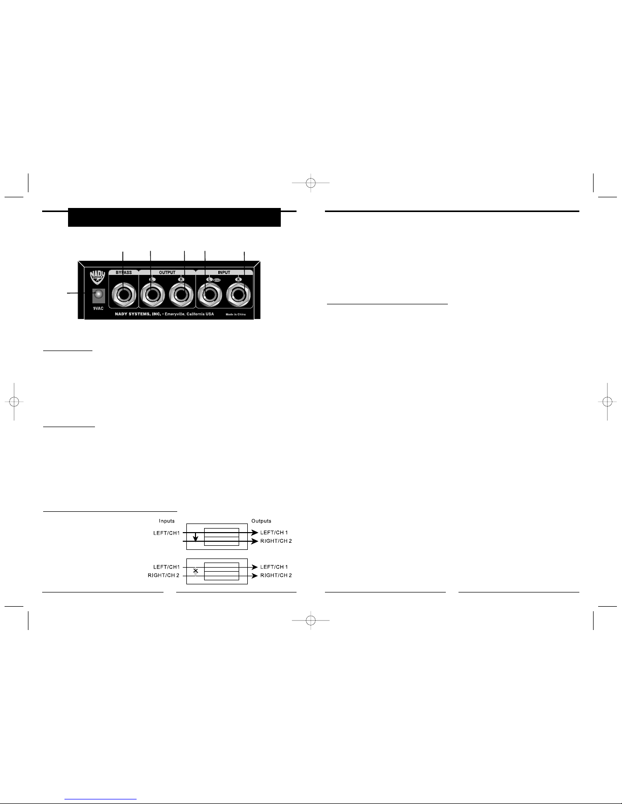
Rear Panel Connections and Use
Power Jacks............................................................8
Bypass Jacks..........................................................8
Input (Left/Mono &Right) Jacks ..............................8
Output (Left & Right) Jacks ....................................9
Setup and Operation
Connecting Directly to an Instrument ..................10
Connecting Directly to a Mixer Console ..............10
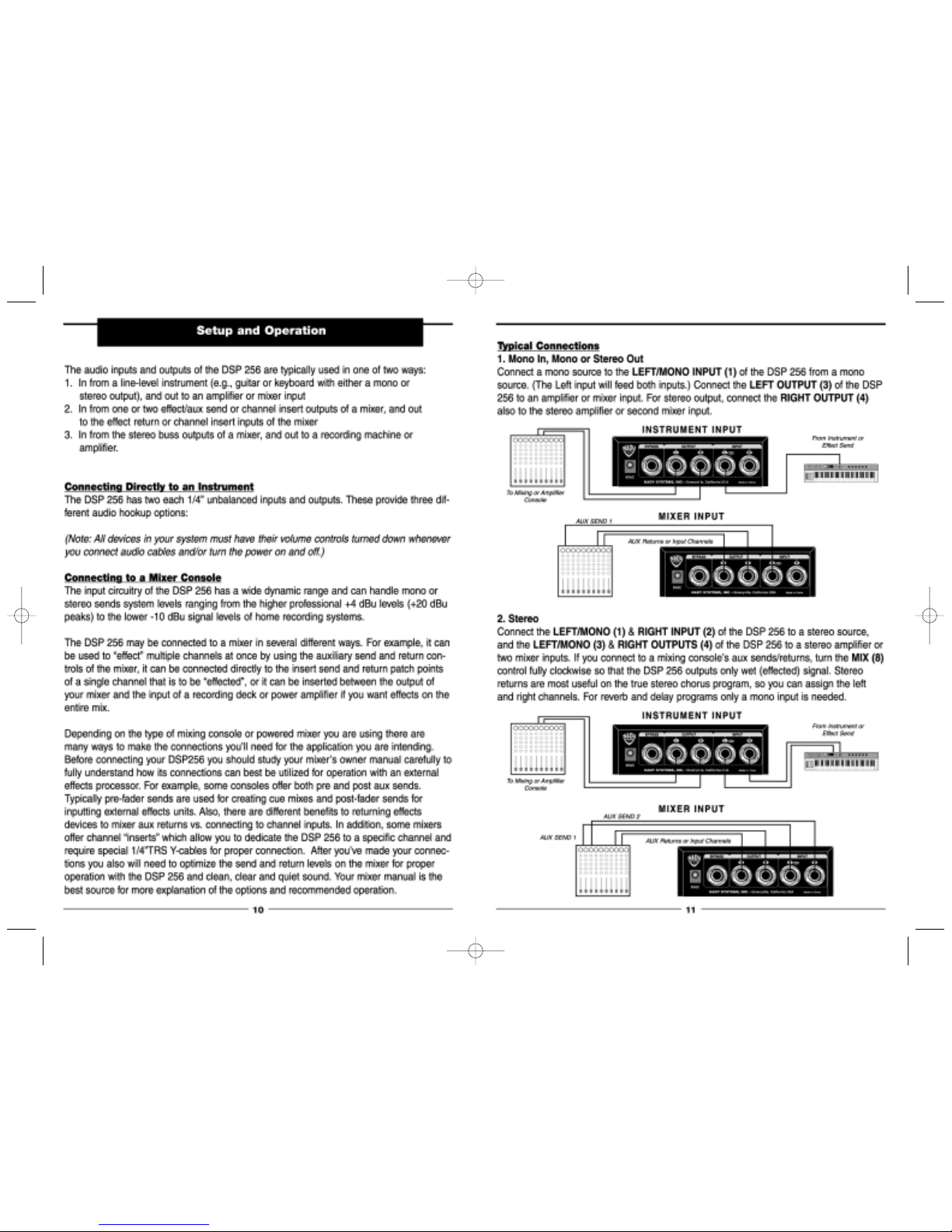
Typical Connections
1. Mono In, Mono or Stereo Out ....................11
2. Stereo..........................................................11
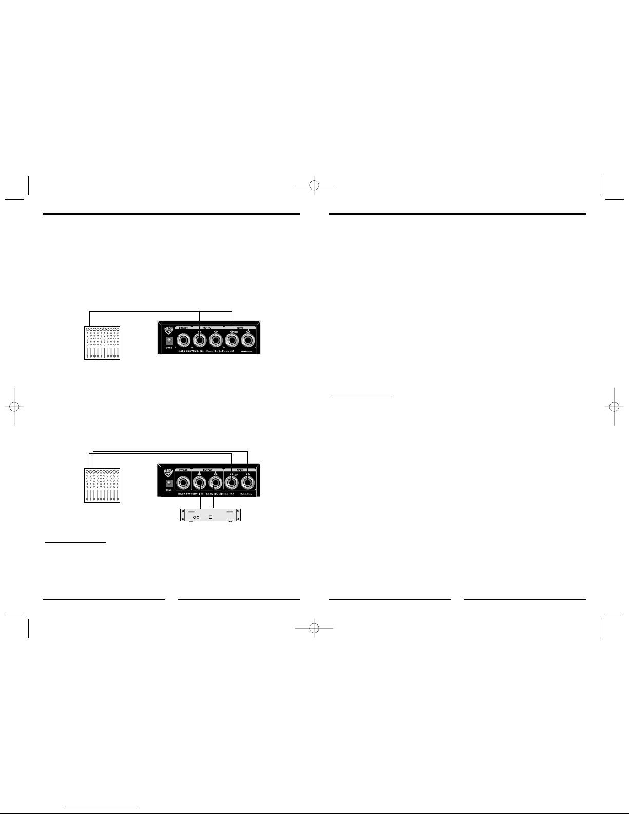
3. Using Mixer Inserts ....................................12
4. Using a Mixer’s Master Outputs ................12
AC Power Hookup................................................12
Line Conditioners..................................................13
Program Descriptions
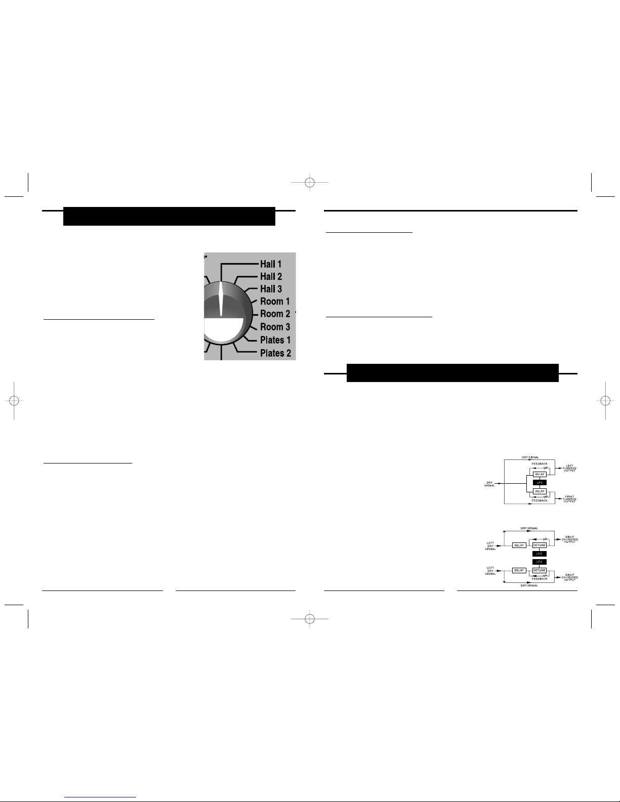
Reverb Effects
Concert Hall Reverb (3 Programs) ......................14
Room Reverb (3 Programs)..................................14
Plate Reverb (2 Programs) ..................................15
Reverb Decay Variations Adjust ..........................15
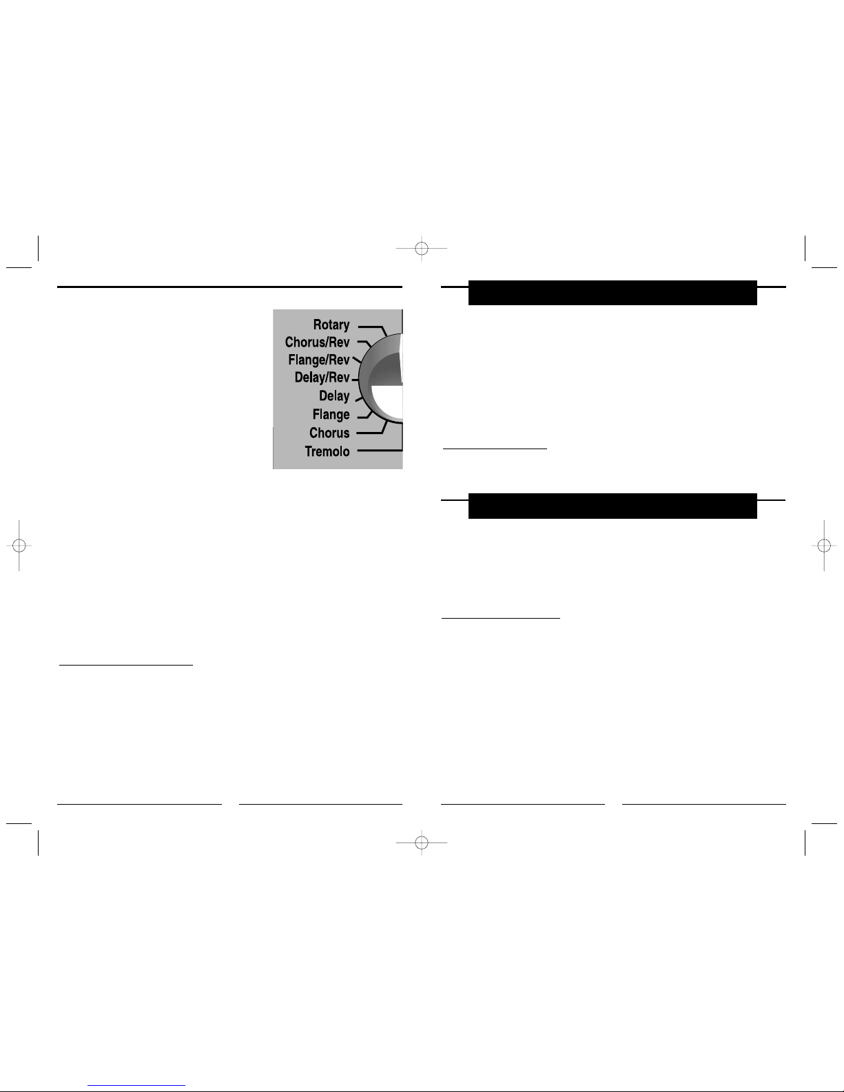
Pitch-Based Effects
Flange ..................................................................15
Chorus ..................................................................15
Chorus/Reverb......................................................16
Flange/Reverb ......................................................16
Rotary ..................................................................16
Pitch-Based Variations Adjust ..............................16
Delay Effects
Delay ....................................................................17
Delay/Reverb........................................................17
Delay Variations Adjust ........................................17
Tremolo
Tremolo Variations Adjust ....................................17
Troubleshooting Guide ....................................18
Specifications......................................................19
Service ..............................................................Back
Contents
122
DSP 256 — 18-bit Digital Sound Processor
Date of Purchase ________________________________________________________
Dealer’s Name __________________________________________________________
Address ________________________________________________________________
State ________________________________Zip ______________________________
Serial # ________________________________________________________________
Congratulations on your purchase of the DSP 256 - you have purchased one of the
finest compact sound processors on the market today. This unit was developed using the
expertise of professional sound engineers and working musicians. You will find that your
new NADYAUDIO sound processor has superior performance and greater flexibility than
any other sound processor in its price range. Please read this manual carefully to get
the most out of your new unit.
FEATURES
• 16 essential effects programs including
ultra smooth, clean, clear hall, room,
plate and gated reverbs; chorus; flang-
ing; delays; combination chorus/reverb;
and even rotating speaker effects
• Each program offers 16 parameter
adjustments for a total of 256 discrete
effects variations
• Easy to use, the DSP-256 offers input,
output, mix, program and variations
select controls
• 1/4” stereo I/O and bypass (for
footswitch control) connectors
• AC adapter (supplied)
• Housed in a small, rugged, easily
portable, all-metal 1/3 rackspace rack
mountable or tabletop package
• DSP-256 is versatile, affordable and
sounds great - perfect for live perform-
ance, multitrack recording and mix down,
and project studios