Page
" C o m p l e t e A i r C o n t r o l a n d D i s t r i b u t i o n S o l u t i o n s . " w w w . n a i l o r . c o m
Calgary, Canada
Tel: 403-279-8619
Fax: 403-279-5035
Houston, exas
Tel: 281-590-1172
Fax: 281-590-3086
oronto, Canada
Tel: 416-744-3300
Fax: 416-744-3360
Las Vegas, Nevada
Tel: 702-648-5400
Fax: 702-638-0400
"Complete Air Control and Distribution Solutions."
Page 2.095 3/16 IO - BFDI P
SPARE PAR S LIS PAR NUMBER
Fusible Links: odel 1200, 1250, 1290 165°F/74°C B2-037
212°F/100°C B2-038
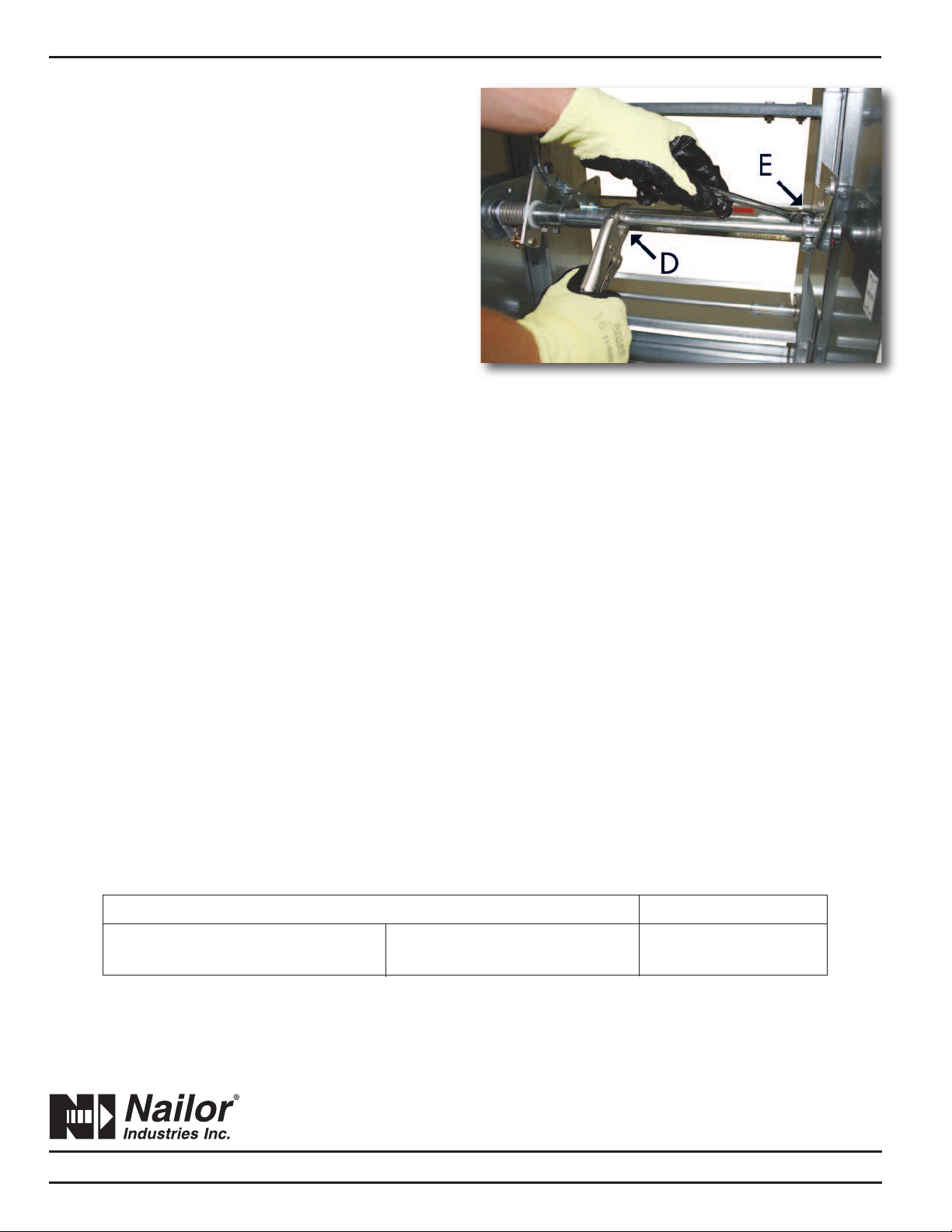
5. anually open the damper to 100% full open position
(D). See Detail 3.
6. Tighten the bolt on the crank arm (E). See Detail 3.
Reopening spring assisted fire dampers may be
extremely difficult and in some cases, impossible. If it
is determined that the damper is impossible or impractical
to test or reopen, a thorough examination of the blade path
is required to ensure that nothing will prevent the damper
from closing. Common obstructions include: racked
damper frames, retaining angle installation screws,
construction debris and contaminants.
Detail 3
Page 2 of 2
Periodic Inspection, esting and Maintenance
Consult your local building code to verify whether there is
a required maintenance and testing schedule. ost local
jurisdictions reference NFPA 80 for Fire Dampers.
Per NFPA 80, each damper should be inspected 1 year
after installation and then every 4 years, except for
hospitals, where the frequency is every 6 years.
1. Remove any obstructions, dirt, rust, corrosion, or other
observed conditions that could impede proper damper
operation. Clean damper blades and other moving parts if
necessary. Use of a mild detergent or solvents is
recommended for any cleaning required.
2. Check closure springs. If damaged or defective, repair
or replace.
3. Linkage and jackshaft bearing brackets should be
lubricated with a dry lubricant (such as T.F.E. Dry Lube).
Never use a regular lubricating oil on dampers, as it will
attract dirt and grit. Blade linkage is concealed in the side
jamb out of the airstream and is maintenance free.
Bearings are self-lubricating oilite bronze (or stainless steel
for -SS models).
4. If firing of the fusible link is not required by local code,
cycle damper with its quadrant handle to verify that it fully
opens and closes. HVAC fans should be shut down. Care
should be exercised to ensure that such tests are
performed safely and do not cause system damage.
5. All inspections and testing shall be documented
indicating the location of the damper, date of inspection,
name of inspector, deficiencies detected, and how
deficiencies were corrected.
Receiving, Storage, Preparation
Upon delivery, inspect shipping containers and contents
closely. Note any damages on freight carrier’s delivery
receipt.
Store dampers in a cool, dry and safe location in an orderly
manner away from construction site, warehouse traffic,
other materials, etc. Cover with plastic sheeting to protect
from excessive moisture, dirt and debris.
Inspect dampers prior to installation. Dampers must be
cleaned per procedures outlined in this document prior to
installation if dirt, rust or corrosion is observed.