E3
MULTI-BLADE FIRE DAMPERS
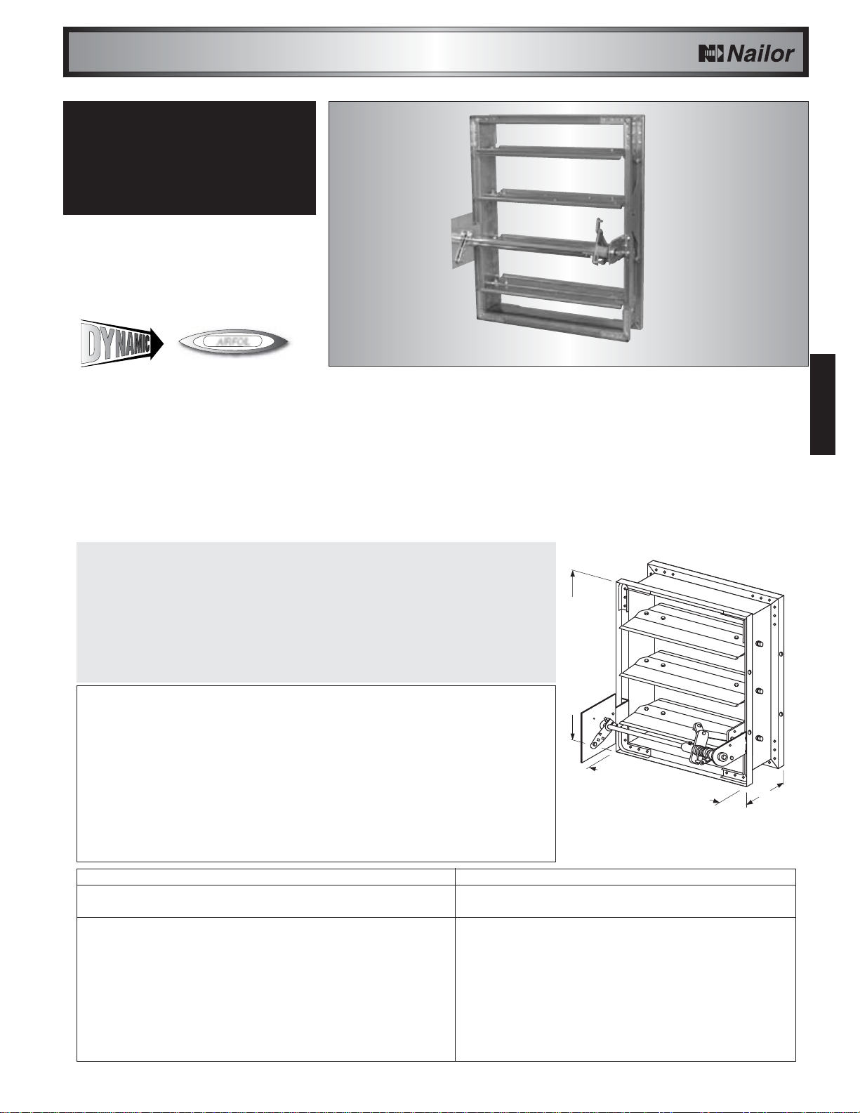
MODEL SERIES D1250
DYNAMIC FIRE DAMPER • VEE-GROOVE BLADE
Model Series D1250, with sturdy vee-groove style blades
and rugged mitered corner hat channel frame design that
virtually eliminates racking, provides 1 1/2 hour UL labeled
fire protection suitable for use where ductwork penetrates a
wall or floor with a fire resistance rating of up to 2 hours. The
over-center/knee lock with high torque spring fusible link
assures fail-safe closure during fire conditions. The D1250
series is also approved for use in both static or dynamic
HVAC system designs. Available with factory fitted sleeve
Model D1251, and choice of transition styles, the series is
supplied as standard with a manual locking quadrant, and is
a versatile and economical performer suitable for use in the
majority of today's applications.
GENERAL PRODUCT OVERVIEW
As today’s modern commercial and industrial building construction becomes increasingly life safety oriented, fire containment
and active smoke management systems are being utilized to a higher degree as more sophisticated technology is developed
and implemented into building codes. The development process begins with the understanding of fire and smoke behavior
through the research and study of real life emergency situations, and culminates in the design, testing of, and ultimate use
of new products to better control and manage the ravages of fire and smoke. Thus, resulting property damage is minimized
and occupant safety is maximized. Nailor Industries commitment to the development of new and existing fire and smoke
control technology has resulted in a comprehensive line of premium quality smoke, fire and combination fire/smoke dampers
and accessories, available at a reasonable cost and in a timely fashion. Nailor's ‘multi-blade’ type fire dampers are available
in several blade and frame styles including ‘true round’, to suit most applications.
E
E3
Model D1200
Model D1201-OW
MODEL SERIES D1200 AND D1200-3
DYNAMIC FIRE DAMPER • AIRFOIL BLADE
PREMIUM PERFORMANCE
Provides the ultimate in fire containment for both static and
dynamic HVAC systems. The D1200 Series utilizes an
innovative inter-locking double skin airfoil blade design that
maintains a complete barrier throughout the fire test with
absolutely no visible through-gaps. Amazingly, the D1200
Series fire damper gets tighter as it gets hotter! Ideal for use
where building codes require a fire damper for the protection
of ductwork penetrations in walls or floors. Premium
performance, versatility and assured closure make the
D1200 Series an excellent choice for the majority of today’s
applications.
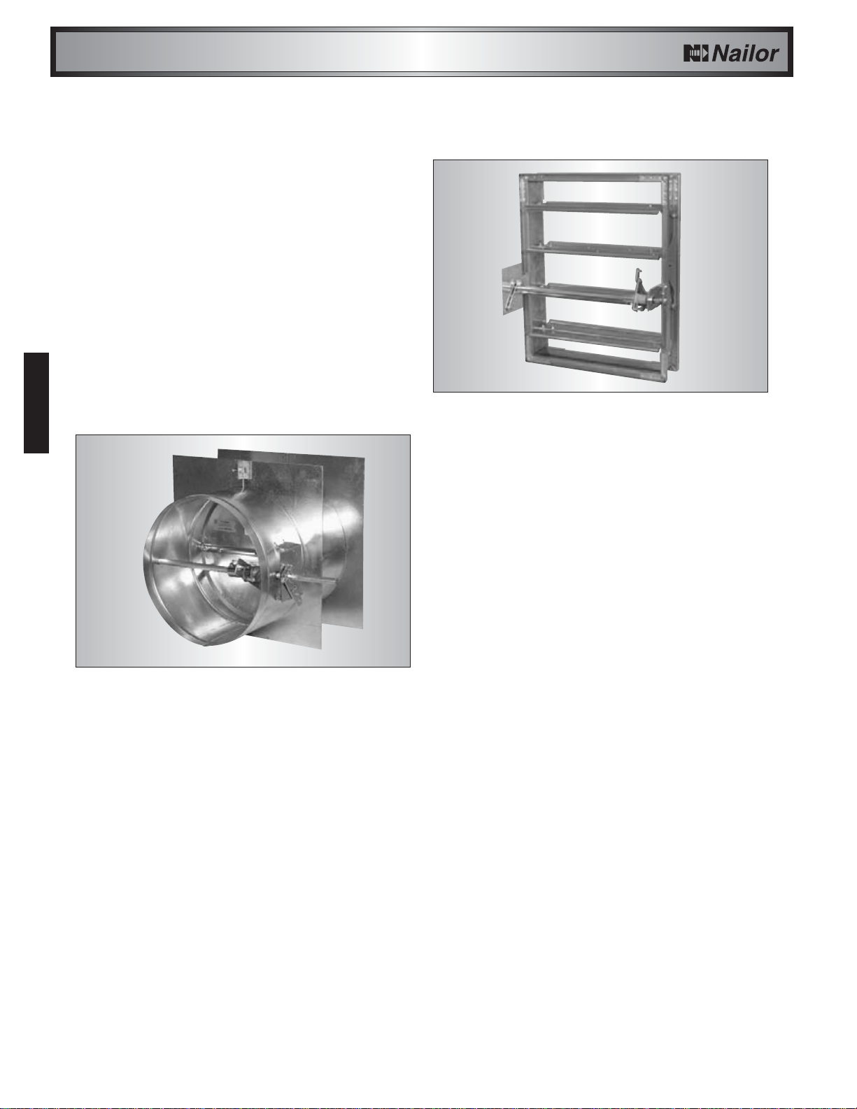
MODEL D1201-OW
DYNAMIC FIRE DAMPER • AIRFOIL BLADE
OUT OF WALL MOUNTING
Model D1201-OW is an "out of wall" high performance fire
damper. It is specifically designed for supply or return ducts
that terminate at a grille and provides through the grille
access to the damper. Standard sleeve length
accommodates most commercial supply and return
grilles/registers. It offers premium performance and a low
pressure drop well suited to the majority of commercial
applications. Unique, inter-locking double skin blade design
eliminates combustible seals and provides flame protection
under fire conditions at temperatures up to 2000°F. The
D1201-OW is supplied as standard with an internal locking
quadrant which holds the damper in the fully open position,
but may also be used for system balancing if required.
Model D1250
MULTI-BLADE FIRE DAMPERS