52
CAUITION
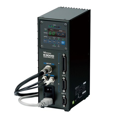
①A motor cooling and spindle purge air is required to operate the system correctly.
②The input air line must be connected to the air input joint on the front of the CONTROLLER. Air
pressure between 0.2 - 0.35MPa (29.0 - 50.8psi) must be supplied.
③The brushless motor and spindle require air for cooling and purging. Ensure that this air
supply is clean and dry. Introduction of dust, moisture and other contaminants into the
CONTROLLER, motor and spindle will cause damage to the internal components.
④If water or oil is allowed to enter the CONTROLLER, failure of the CONTROLLER may result.
⑤Do not hit, drop or subject the motor, spindle or CONTROLLER to any type of shock. This will
cause damage to internal components and result in a malfunction.
⑥Do not disassemble, modify or attempt to repair the CONTROLLER, motor or spindle as it will
damage internal components. There are no user serviceable parts available.
⑦Motor will make a sudden stop when error LED lights or error output signal is generated. Check
and correct the cause of the malfunction before continuing use. Failure to correct the problem
will result in damage to the CONTROLLER, motor and spindle.
⑧When the warning LED on the CONTROLLER blinks, conditions exist that could result in
dangerous operation. Check operating conditions and continue to use only after correcting the
problem.
⑨When using CONTROLLER continuously, refer to continuous area on torque Characteristics
Graph and check Load Monitor LED for a maximum output of (3 Green LEDs).
⑩Do not install the CONTROLLER next to RF noise sources, as malfunctions can occur.
⑪If smoke, noise or strange odors eminate from the CONTROLLER or motor spindle, immediately
turn OFF the Main Power Switch.
⑫Do not place anything on top of the CONTROLLER.
⑬When installing the CONTROLLER, never place them in areas where vibration and shock are
present or possible. This may cause a malfunction to occur.
⑭Do not place the CONTROLLER near any source of heat. The temperature inside the
CONTROLLER will rise, resulting in a CONTROLLER failure.
⑥Do not use in dangerous environments. Protect the CONTROLLER from moisture and other
contaminants. Failure to protect CONTROLLER can result in damage to internal components
and injury to the operator.
⑦To protective CONTROLLER or electric wiring from a possible short circuit, place a circuit
breaker (MCCB) between the power source and the AC Power Input Terminal Block of the
CONTROLLER. Select the circuit breaker with a 10A current capacity.
⑧Check to ensure that the supply voltage is the same as the CONTROLLER rated voltage.
⑨When you use the E4000 Safety Relay Box, connect the E4000 Safety Relay Box to the E4000
CONTROLLER. By doing this, the outer box of E4000 Safety Relay Box is grounded and the
system will be protected against electric shock.
⑩When installing a tool, tighten the collet correctly and check again the collet and collet nut
before use. Do not over-tighten the collet. This may cause damage to the spindle.
⑪Do not use bent, broken, chipped, out of round or sub-standard tools as they may cause tools
to shatter or explode. Tool with fractures or a bent shank will cause injury to the operator.
When using a new tool, rotate it at a low speed and increase speed gradually for safety.
⑫Do not exceed the maximum recommended allowable tool speed. For your safety, use speeds
below the maximum allowable speed.
⑬Do not apply excessive force. This may cause tool slippage, tool damage, injury to the operator
or loss of concentricity and precision.
⑭When installing the motor and the spindle, make sure the Main Power Switch of the
CONTROLLER turned OFF before installing.
⑮When installing a motor spindle to a ¿xed base, make sure the ¿xed base is grounded in order
to avoid the risk of an electric shock.
WARNING


