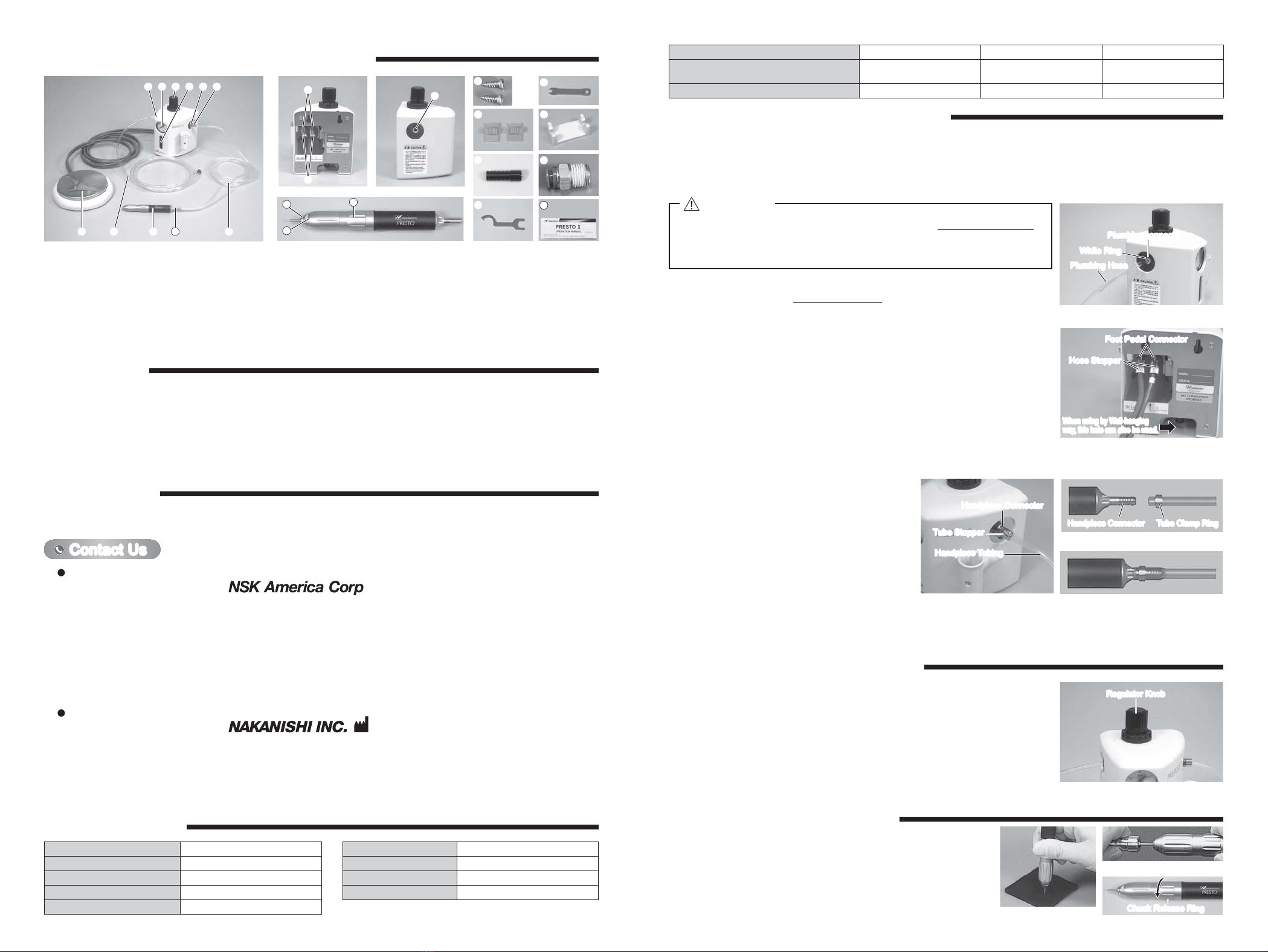
①PRESTOϩControl Unit ⑧Plumbing Hose ⑮Handpiese Tubing Clamps ㉒Wrench Flats
②Pressure Gauge ⑨PRESTO Handpiece ⑯Bur Push-in Tool ㉓Chuck Release Ring
③Regulator Knob ⑩Handpiece Tubing ⑰Cartridge Wrench ㉔Tube Clamp Ring
④Filter Inspection Window ⑪Foot Pedal Connector ⑱Rotor Shaft Nut Wrench ㉕Operation Manual
⑤Handpiece Connector ⑫Hose Stopper ⑲Handpiece Stand
⑥Tube Stopper ⑬Plumbing Connector ⑳Air Supply Connector
⑦Foot Pedal ⑭Unit Mounting Screws ㉑Cartridge
speed 320,000min-1 (rpm)
Recommended Air Pressure 0.2 - 0.25MPa (29 - 36.3psi)
Handpiece Dimensions ȭ16.6 (D) x 130 (H) mm
Handpiece Weight 71g
Noise Level at 1m distance Less than 70dB (A)
6 - 1 Mounting of the Control Unit
The Control Unit can be secured on a wall, on a work-bench, or under a work-bench.
When securing on a wall surface, etc., x the Control Unit with unit xing screws in the two screw holes on its back.
Control Unit Dimensions W120 x D102 x H165 (mm)
Control Unit Weight 720g
Proper Air Pressure 40Nℓ/ min
Inside Diameter ȭ1.6mm Bur Only
6 - 2 Installation of Plumbing Hose
WARRANTY3.
COMPONENT NAMES AND BASIC PACKAGE
2.
We provide a limited warranty for our products. We will repair or replace the products if the cause of failure is due to the following
manufactures defects. Please contact us or your local distributor for details.
①Defect in manufacturing.
②Any shortage of components in the package.
③Where damaged components are found when initially opening the package.
(This shall not apply if the damage was caused by the negligence of a customer.)
CONTACT US4.
For your safety and convenience when purchasing our products, we welcome your questions.
If you have any questions about operation, maintenance and repair of the product, please contact us.
Company Name
Business Hours
U.S. Toll Free No.
Telephone No.
Fax No.
Web Address
:
Industrial Div.
: 8:30am to 17:00pm (CST)
(closed Saturday, Sunday and Public Holidays)
: 800-585-4675
: 847-843-7664
: 847-843-7622
: www.nskamericacorp.com
Contact UsContact Us
For U.S. Market
Company Name
Business Hours
Telephone No.
e-mail Address
:
: 8:00am to 17:00pm
(closed Saturday, Sunday and Public Holidays)
: +81 (0) 289-64-3520
For Other Markets
SPECIFICATIONS5.
Temperature Humidity Atmospheric Pressure
Operation Environment 0 - 40°CMAX.75%
(No condensation) 700 - 1,060hPa
Transportation and Storage Environment -10 - + 50°C 10 - 85% 500 - 1,060hPa
Push the plumbing hose into the plumbing connector located at the regulator on the left-
hand side of the Control Unit until it is securely set to make connection as shown in Fig. 1.
Check if the hose is securely installed by tugging it after connection.
Connect the other end of the plumbing hose to the air line. At this time, use the attached
connector if necessary.
Plumbing connectorPlumbing connectorPlumbing connector
Plumbing HosePlumbing Hose
White RingWhite Ring
Fig. 1
SYSTEM ASSEMBLY PROCEDURES6.
・
Push the plumbing hose into the plumbing connector until it is securely set.
Otherwise, air may leak.
・
Pushing the white ring, on the plumbing connector, gently remove the tube.
CAUTION
6 - 3 Installation of foot Pedal
Loosen and remove the hose stoppers (two) from the foot pedal connectors on the back
of the Control Unit, and insert them into the foot pedal hoses. At this time, insert the hose
stoppers so that their screws come outside (Control Unit side) (Fig. 2)
. For wall-hanging
use, pass the hoses through the hole shown in Fig. 2.
Insert the "1" - marked end of each hose according to the instructions on the label. After
insertion of both hoses, securely tighten the hose stoppers.
Foot Pedal ConnectorFoot Pedal Connector
When using by Wall-hanging
way, this hole can also be used.
Hose StopperHose Stopper
When using by Wall-hanging
way, this hole can also be used.
Fig. 2
6 - 4 Installation of Handpiece
Loosen and remove the tube stopper from the handpiece
connector on the right-hand side of the Control Unit, and insert
it into the handpiece tubing. At this time, insert the tube stopper
so that its screw comes outside (Control Unit side) (Fig. 3).
Insert the handpiece tubing into the handpiece connector, and
securely tighten the tube stopper.
Insert the tube clamp ring into the other end of the handpiece
tubing as shown in Fig. 4, and insert it into the handpiece
tubing socket as shown in Fig. 5.
Handpiece ConnectorHandpiece Connector
Handpiece Tubing
Handpiece Tubing
Tube Stopper
Tube Stopper
Fig. 3 Fig. 5
Handpiece ConnectorHandpiece Connector Tube Clamp Ring
Tube Clamp Ring
Fig. 4
6 - 5 Installation of Handpiesce Tubing Clamps
Locate a Handpiece Tubing Clamp (two pieces supplied) at a proper location to conveniently position the handpiece tubing.
7 - 1 Set the Drive Air Pressure
Supply air, and adjust to 0.25MPa (36.3psi) by pulling the Regulator Knob upward and turning.
When adjustment is made, push the knob down to lock (Fig.6).
7 - 2 Operation
Stepping on the Foot Pedal starts rotation.
7 - 3 For Finishing Work
Close the main air valve.
Regulator KnobRegulator Knob
Fig. 6
OPERATION OF CONTROL UNIT
7.
①As the chuck of the PRESTO handpiece is a push-in type, set the
ȭ1.6mm burs and push in as shown in Fig.7.
If the end of the bur is tapered push in using the provided bur-
inserting wrench as shown in Fig.8.
②When removing the bur, turn the chuck release ring in the direction
of the arrow in Fig.9. Fig. 7 Chuck Release RingChuck Release Ring
Fig. 9
Fig. 8
OPERATION OF HANDPIECE
8.
① ② ③④⑤⑥
⑦⑧ ⑨ ⑩
⑪
⑫
⑬
23 25
21
24 22
⑭
⑮
⑯
⑰
⑱
⑲
⑳


