Nakanishi PRESTO II User manual

OPERATION MANUAL
Class Degree of Risk
WARNING
A safety hazard could result in bodily injury or damage to the device if the safety
instructions are not properly followed.
CAUTION A hazard that could result in light or moderate bodily injury or damage to the
device if the safety instructions are not followed.
PRESTO
î
OM-K0516E Rev.A
Thank you for purchasing the PRESTO ϩ.
Please read this manual carefully, and store it in a place where it can be easily accessed for future reference.
1. CAUTIONS FOR HANDLING AND OPERATION
■Read these warnings and cautions carefully and only use in the manner intended.
■These warnings and cautions are intended to avoid potential hazards that could result in personal injury or damage to the
device. These are classified as follows in accordance with the seriousness of the risk.
WARNING
①Do not touch the cutting tool while it is running.
②Use a protective cover, glasses and / or facemask for your safety during rotation.
③Do not drop or hit the attachment because the shock can damage internal components.
④Do not force or bend the cutting tool. The shank might be broken and / or bent.
⑤Check if the collet chuck has been tightened firmly before operation.
⑥Observe the permissible speeds the manufacturer or dealer designates for the bur. Otherwise, you may be
injured by scattering and breaking up of the bur.
⑦Do not use burs which are oscillating or bent or damaged and of which shank portions are worn.
Otherwise, you may be injured by scattering and breaking up of the bur.
CAUTION
①Do not modify or disassemble unnecessarily, performance and safety may be seriously affected.
②Do not drop the handpiece and unit. Make sure to put the unit on a horizontal and stable surface.
③
Do not turn the chuck release ring during rotation of the handpiece. Otherwise, the handpiece will be broken.
④Never supply lubricant to the handpiece. It uses grease filled bearings and additional lubrication may
cause failures.
⑤
Pay careful attention to rattling, vibration, sounds and temperature (heating), and inspect by rotating in
advance before starting use. Immediately ask dealers for repair work if any irregularities are sensed.
⑥The proper air pressure is 0.2 〜0.25MPa. Pressure exceeding the value may lead to premature failure of
the bearings because of excessive speeds.
⑦Extract water if water drips or contaminants are found on the filter of the unit.
⑧Always clean the shank of the bur you are going to mount. Contaminant deposits in the chuck may lead to
oscillating of the bur and break the chuck.
⑨Install the cutting bur or test bur when not in use.
⑩Operational control, maintenance and inspection is the responsibility of each user.
2012.09.20 002 S
8. REPLACEMENT OR CLEANING PROCEDURES OF CHUCK
CAUTION
As the guide-bush is a very small part, be careful not to lose it.
NOTICE
Remove the chuck and clean once a week.
8 - 1 Removal of Chuck
①Remove the cartridge with a bur or dummy bur installed.
(7. REPLACEMENT OF CARTRIDGE)
②Hold the rotor with two fingers as shown on the Fig.11.
Mount the wrench provided on the rotor nut located on the top of rotor shaft and
turn counterclockwise. (Either side of wrench can be used.)
③When the rotor nut is loose. Push out the chuck carefully with a dummy bur or the
bur shank from the back of the cartridge, the Guide-bush and the chuck will come
out. (Fig.12)
・When cleaning the chuck, clean it with ultrasonic cleaner etc.
Spray oil to the inside of the rotor shaft and clean thoroughly.
Fig. 11
Test Bur
Test Bur
Chuck Guide-bush
Fig. 12
8 - 2 Installation of a New Chuck
①Apply oil thinly on the surface of the new chuck or the chuck after cleaning, insert the test bur and push into the rotor shaft.
(Fig.13)
②Set the longer one of the guides of the guide bushings on the end of the rotor shaft along the test bur. (Fig.14)
③Finally insert the rotor shaft nut along the test bur, and tighten firmly with a wrench while holding the rotor. (Fig.15)
Rotor Shaft Nut
Fig. 15
Guide-bush
Fig. 14
Chuck
Test bur
Fig. 13
9. MAINTENANCE OF UNIT
9 - 1 Draining the Filter
Check the filter bowl from the filter inspection window, and if there is an accumulation
of water, insert fingers from the bottom, and turn the drain valve in the direction of the
arrow (counterclockwise) to drain water from the filter. (Fig. 16)
After draining, securely tighten the drain valve by turning it in the reverse direction.
Fig. 16

①PRESTOϩControl Unit ⑦Foot Pedal ⑬Plumbing Connector ⑲Handpiece Stand
②Pressure Gauge ⑧Plumbing Hose ⑭Unit Mounting Screws ⑳Air Supply Connector
③Regulator Knob ⑨PRESTO Handpiece ⑮Handpiese Tubing Clamps ㉑Cartridge
④Filter Inspection Window ⑩Handpiece Tubing ⑯Bur Push-in Tool ㉒Wrench Flats
⑤Handpiece Connector ⑪Foot Pedal Connector ⑰Cartridge Wrench ㉓Chuck Release Ring
⑥Tube Stopper ⑫Hose Stopper ⑱Rotor Shaft Nut Wrench
2. COMPONENT NAMES
3. SPECIFICATIONS
Speed 320,000min-1
Recommended Air Pressure 0.2 〜.25MPa
Handpiece Dimensions ȭ16.6 (D) X130 (H) mm
Handpiece Weight 71g
Control Unit Dimensions W120 X D102 X H165 (mm)
Control Unit Weight 720g
Proper Air Pressure 40Nℓ/ min
Inside Diameter ȭ1.6mm Bur Only
4. SYSTEM ASSEMBLY PROCEDURES
4 - 1 Mounting of the Control Unit
The Control Unit can be secured on a wall, on a work-bench, or under a work-bench.
When securing on a wall surface, etc., fix the Control Unit with unit fixing screws in the two screw holes on its back.
4 - 2 Installation of Plumbing Hose
Push the plumbing hose into the plumbing connector located at the regulator on
the left-hand side of the Control Unit until it is securely set to make connection
as shown in Fig. 1. Check if the hose is securely installed by tugging it after
connection.
Connect the other end of the plumbing hose to the air line. At this time, use the
attached connector if necessary.
CAUTION
・Push the plumbing hose into the plumbing connector until it is securely set. Otherwise, air may leak.
・Pushing the white ring, on the plumbing connector, gently remove the tube.
Plumbing connector
Plumbing Hose
White Ring
Plumbing connector
Plumbing Hose
White Ring
Fig. 1
4 - 3 Installation of foot Pedal
Loosen and remove the hose stoppers (two) from the foot pedal connectors on the
back of the Control Unit, and insert them into the foot pedal hoses. At this time,
insert the hose stoppers so that their screws come outside (Control Unit side). (Fig. 2)
For wall-hanging use, pass the hoses through the hole shown in Fig. 2.
Insert the "1" - marked end of each hose according to the instructions on the
label. After insertion of both hoses, securely tighten the hose stoppers.
Foot Pedal Connector
Hose Stopper
When using by Wall-hanging
way, this hole can also be used.
Foot Pedal Connector
Hose Stopper
When using by Wall-hanging
way, this hole can also be used.
Fig. 2
4 - 4 Installation of Handpiece
Loosen and remove the tube stopper from the handpiece
connector on the right-hand side of the Control Unit, and insert
it into the handpiece tubing. At this time, insert the tube stopper
so that its screw comes outside (Control Unit side). (Fig. 3)
Insert the handpiece tubing into the handpiece connector, and
securely tighten the tube stopper.
Insert the tube clamp ring into the other end of the handpiece
tubing as shown in Fig. 4, and insert it into the handpiece
tubing socket as shown in Fig. 5.
Handpiece Tubing
Handpiece Connector
Tube Stopper
Handpiece Tubing
Handpiece Connector
Tube Stopper
Fig. 3 Fig. 5
Tube Clamp RingHandpiece Connector Tube Clamp RingHandpiece Connector
Fig. 4
4 - 5 Installation of Handpiesce Tubing Clamps
Locate a Handpiece Tubing Clamp (two pieces supplied) at a proper location to conveniently position the handpiece tubing.
5. OPERATION OF CONTROL UNIT
5 - 1 Set the Drive Air Pressure
Supply air, and adjust to 0.25MPa by pulling the Regulator Knob upward and turning.
When adjustment is made, push the knob down to lock. (Fig.6)
5 - 2 Operation
Stepping on the Foot Pedal starts rotation.
5 - 3 For Finishing Work
Close the main air valve.
Regulator Knob
Fig. 6
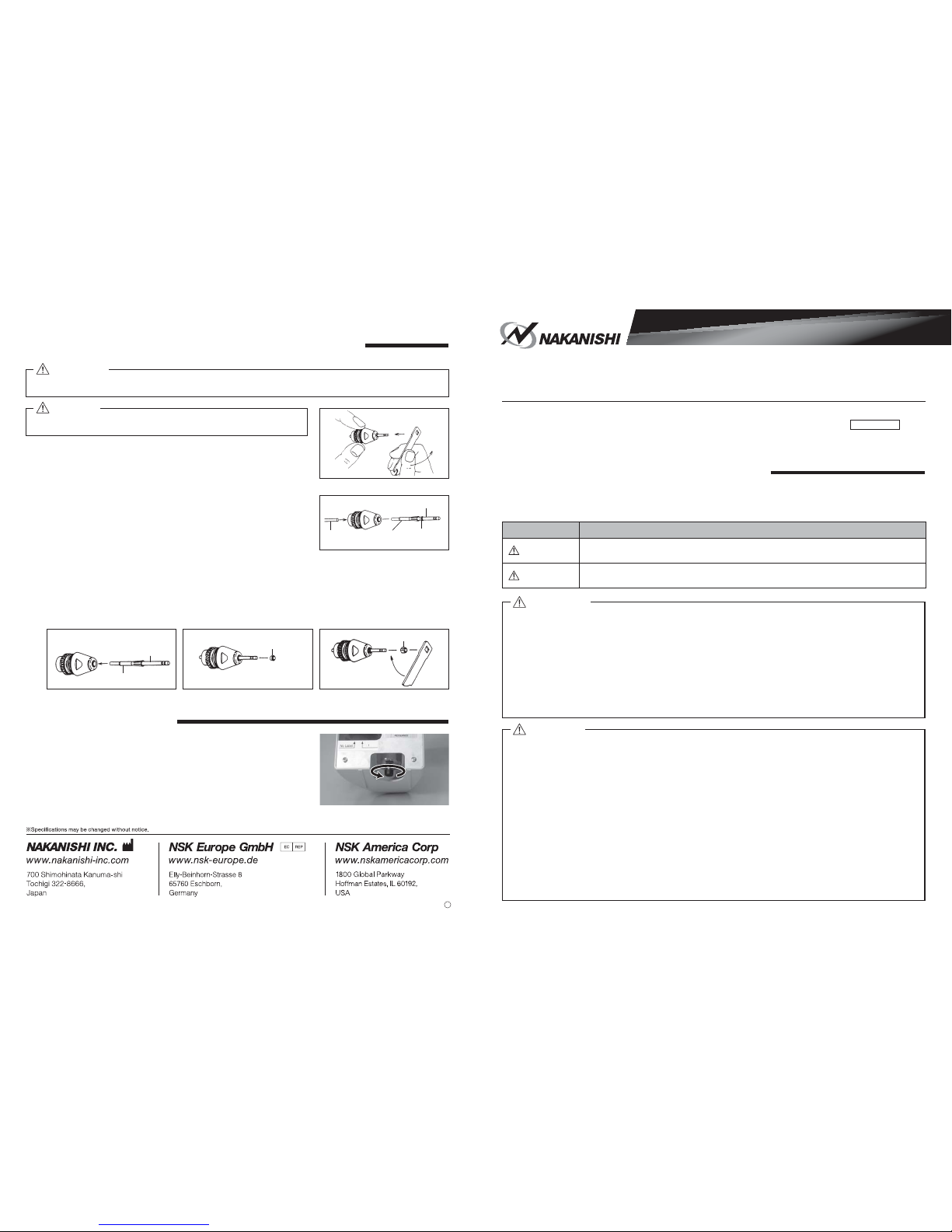
6. OPERATION OF HANDPIECE
①As the chuck of the PRESTO handpiece is a push-in type, set the
ȭ1.6mm burs and push in as shown in Fig.7.
If the end of the bur is tapered push in using the provided bur-
inserting wrench as shown in Fig.8.
②When removing the bur, turn the chuck release ring in the direction
of the arrow in Fig.9.
Fig. 7 Chuck Release Ring
Fig. 9
Fig. 8
7. REPLACEMENT OF CARTRIDGE
①Fit the cartridge wrench supplied with the handpiece to the flats on the handpiece
nose. Turn the cartridge wrench as shown in (Fig.10) after it is loosened, unscrew
the nose with fingers and remove from the handpiece.
②Before inserting a new cartridge, clean the head interior.
③Finally, securely tighten the cartridge by turning it in the reverse direction to
removal.
Fig. 10
① ② ③④⑤⑥
⑦⑧ ⑨ ⑩
⑪
⑫
⑬
23
21
22
⑭
⑮
⑯
⑰
⑱
⑲
⑳
Other Nakanishi Laboratory Equipment manuals
Popular Laboratory Equipment manuals by other brands

TestEquity
TestEquity 1007C Operation and service manual

A&D
A&D MPA-20 Quick operation guide

Trojan Technologies
Trojan Technologies Viqua Sterilight Silver S1Q-PA owner's manual

MRC
MRC MDCEN-302-SMD user manual

Koehler
Koehler K430X2 Operation and instruction manual

Monmouth Scientific
Monmouth Scientific Circulaire PCB1800 operating & maintenance manual