manuals.online logo
Brands
  1. Home
  2. •
  3. Brands
  4. •
  5. Nakanishi
  6. •
  7. Power Tools Accessories
  8. •
  9. Nakanishi IH-300 User manual

Nakanishi IH-300 User manual

IH - 300
Lever Type Attachment
Thank you for purchasing the Lever Type Attachment " IH - 300 ". This Lever Type
Attachment designed for using the Emax EVOlution motor or Espert 500 motor. The Emax
EVOlution Control Unit and Motor / ROTUS Air Motor and Air Line Kit are required to
drive this Lever Type Attachment. Read this and all the associated component Operation
Manuals carefully before use. Always keep this Operation Manual in a place where a user
can referred to for reference at any time.
OPERATION MANUAL OM-K0153E 002
CAUTIONS FOR HANDLING AND OPERATION
Class Degree of Risk
WARNING
A safety hazard could result in bodily injury or
damage to the device if the safety instructions are
not properly followed.
CAUTION
A hazard that could result in light or moderate
bodily injury or damage to the device if the safety
instructions are not followed.
1.
■Read these warnings and cautions carefully and only use in the manner intended.
■These warnings and cautions are intended to avoid potential hazards that could result
in personal injury to the operator or damage to the device. These are classi¿ed as
follows in accordance with the seriousness of the risk.
①This Attachment is designed for hand use. Never install this Attachment or
any hand cutting tool on a machine such as a special purpose machine, NC
lathe or mill.
②Do not touch the cutting tool while it is rotating. It is very dangerous.
③Wear safety glasses, dust mask, and use a protective cover around the
Attachment whenever the Attachment is rotating.
④When installing a cutting tool, tighten the collet correctly and check again
the collet before use. Do not over-tighten the collet. This may cause
damage to the spindle.
⑤Do not use grindstones with an outside diameter over ₥15mm.
⑥Do not exceed 13mm of overhang for mounted grindstones as shown
in Fig. 1. If the overhang must exceed 13mm, reduce the motor speed in
accordance with Table 1.
⑦Do not use bent, broken, chipped, out of round or sub-standard cutting
tools as they may cause shatter or explode.
The cutting tool with cracked, bended may cause some injury to operator.
When using a new cutting tool, rotate it in a low speed and increase speed
gradually for safety.
⑧Always operate cutting tools within the cutting tool manufacturer's
recommended speed limits. Use of a cutting tool higher than the
manufacturer's recommended speed limits could cause damage to the
spindle and injury to the operator.
⑨Do not apply excessive force. This may cause cutting tool slippage, cutting
tool damage, injury to the operator, loss of concentricity and precision.
WARNING
Table. 1 Overhang and Speed
Overhang (mm) Max. Speed (min-1) (rpm)
20 N x 0.5
25 N x 0.3
50 N x 0.1
*N = Max. Operating Speed with 13mm overhang.
13
Fig. 1
①Do not drop or hit this Attachment, as shock can damage to the internal
components.
②Be sure to clean the collet, the spindle taper and threads before replacing
the cutting tool. If ground particles or metal chips stick to the inside of
spindle or the collet, damage to the collet or spindle can occur due to the
loss of precision.
③When cleaning an Attachment, stop the motor and remove dirt with a
brush or a cloth. Do not blow compressed air into the Attachment. Foreign
particles or cutting chips may get into the ball bearings.
④Always clean the cutting tool shank before installing the cutting tool in the
spindle.
⑤When sizing the correct collet size to the cutting tool shank diameter, a
tolerance of +0 〜
-
0.01mm is strongly recommended.
A cutting tool shank within the +0 〜
-
0.1mm range is mountable, however,
this may cause poor concentricity and or insuf¿cient cutting tool shank
gripping force.
⑥Select suitable products or cutting tools for each application. Do not
exceed the capabilities of the Attachment or cutting tools.
⑦Keep everything in order not to place the rag which could be caught near
the hand tool.
CAUTION
⑧Stop operating immediately when abnormal rotation or unusual vibrations
are observed. Immediately, please check the content of section
" 10. TROUBLESHOOTING ".
⑨
Always check if the cutting tool, collet is damaged before and after operating.
⑩If the collet show signs of wear or damage, replace it before a malfunction
or additional damage occurs.
⑪No lubrication is required because grease impregnated ball bearings are
used.
⑫After installation, repair, initial operation, or long periods of non operation,
please carry out break-in as follow. Start rotating slowly and over a short
period of 5 - 10 minutes, increase speed gradually until allowable maximum
speed.
⑬Do not disassemble, modify or attempt to repair the Attachment. Additional
damage will occur to the internal components. Service must be performed
by NSK NAKANISHI or an authorized service center.
CAUTION
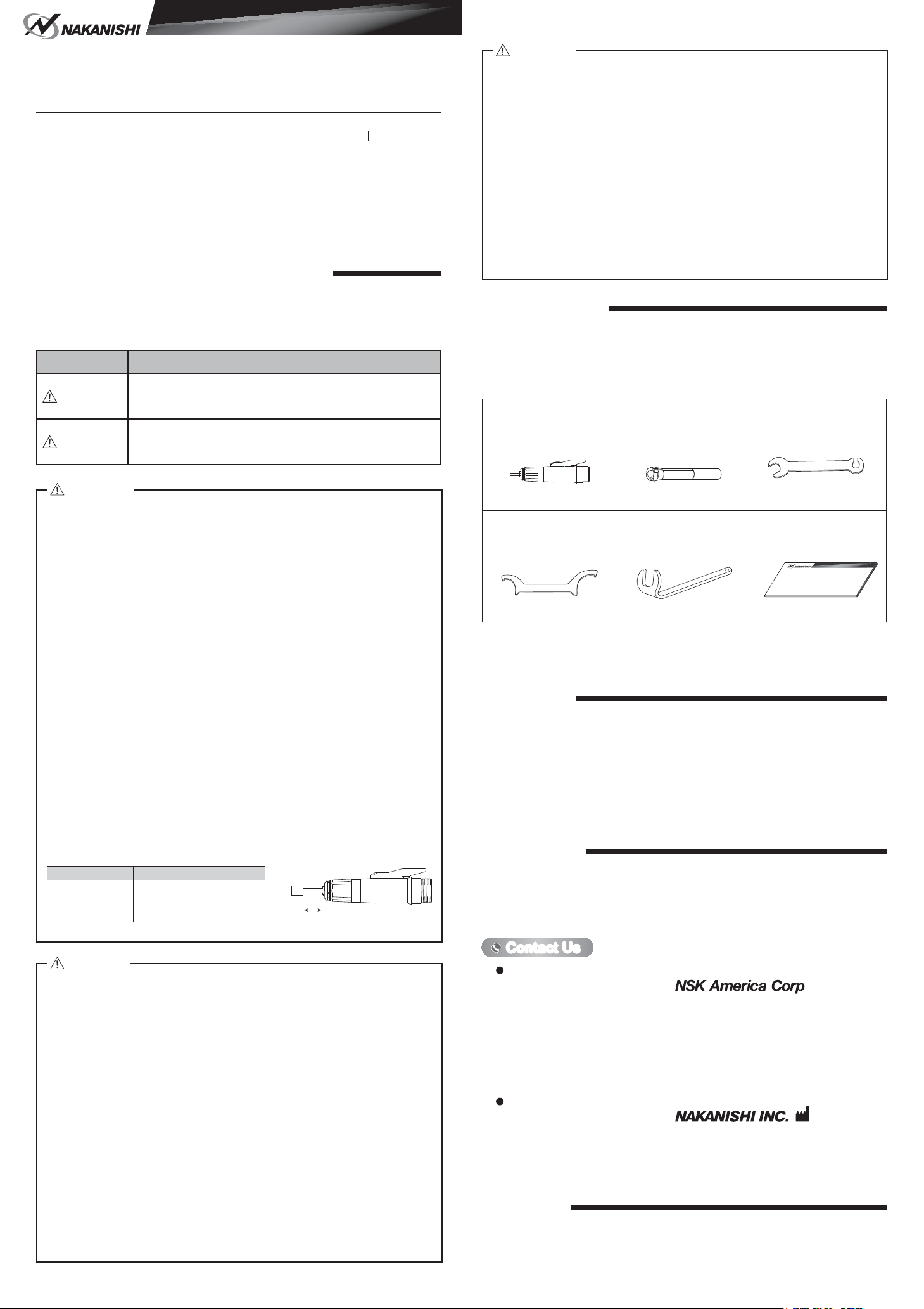
Attachment・・1pc. Collet* Wrench (7 x 5.1)・・1pc.
5.1
7
Pin Wrench (K - 233)・・1pc.
L Shaped Wrench・・1pc. Operation Manual・・1set
ྲྀᢅㄝ󰩣᭩
OPERATION MANUAL
* ȭ3.0mm (CHH - 3.0) or ȭ3.175mm(CHH - 3.175) and ȭ2.35mm (CHH - 2.35)・・1pc. Each.
(For U.S. market ȭ3.175mm (CHH - 3.175)) and ȭ2.35mm (CHH - 2.35)
The collet is attached to the Attachment.
BASIC PACKAGE2.
When opening the package, check if it includes all items listed in " Table. 2 Packing List
Contents ".
In the event of any shortage, please contact either NAKANISHI (see the " 4. CONTACT
US " section) or your local dealer.
Table. 2 Packing List Contents
WARRANTY3.
We provide a limited warranty for our products. We will repair or replace the products if the
cause of failure is due to the following manufactures defects. Please contact us or your
local distributor for details.
①Defect in manufacturing.
②Any shortage of components in the package.
③Where damaged components are found when initially opening the package.
(This shall not apply if the damage was caused by the negligence of a customer)
CONTACT US4.
For your safety and convenience when purchasing our products, we welcome your
questions.
If you have any questions about operation, maintenance and repair of the product, please
contact us.
Company Name
Business Hours
U.S. Toll Free No.
Telephone No.
Fax No.
Web Address
:Industrial Div.
: 8:30am to 17:00pm (CST)
(closed Saturday, Sunday and Public Holidays)
: 800-585-4675
: 847-843-7664
: 847-843-7622
: www.nskamericacorp.com
Contact UsContact Us
For U.S. Market
Company Name
Business Hours
Telephone No.
e-mail Address
:
: 8:00am to 17:00pm
(closed Saturday, Sunday and Public Holidays)
: +81 (0) 289-64-3520
: [email protected]
For Other Markets
FEATURES5.
①The cutting tools can be surely replaced by " Lever Type Chucking ".
②This Attachment is a slim, light weight and best for micro-drilling or micromillimg.
③This Attachment can be used forAir Motor with Chip Air Mechanism (IM - 300).
SPECIFICATIONS AND DIMENSIONS6.
6 - 1 Speci¿cations
Model IH - 300
Maximum Motor Rotation
Speed Less than 40,000min-1 (rpm)
Appropriate Motor ENK - 410S, ENK - 250T
IM - 300, IM - 301
(Emax EVOlution)
(ROTUS)
Vibration Level m / s2Less than 2.5m / s2
Weight 62g
Noise Level at 1m distance Less than 70dB (A)
Temperature Humidity Atmospheric
Pressure
Operation Environment 0 - 40°C MAX.75%
(No condensation)
800 - 1,060hPa
Transportation and
Storage Environment -10 - 50°C 10 - 85%500 - 1,060hPa
<Option>
Collet
(CHH - □□ )
ȭ1.0mm, ȭ1.5mm, ȭ1.6mm, ȭ2.0mm, ȭ2.35mm,
ȭ2.5mm, ȭ3.0mm, ȭ3.175mm
6 - 2 Outside View
Fig. 2
CONNECTION OF THE ATTACHMENT TO THE MOTOR7.
Make sure your hands and all interlocking parts of the Attachment and motor
are clean before connecting the motor to the Attachment. This is critical to
preventing contaminants from entering the motor or Attachment.
CAUTION
Tighten
Transmission Clutch
Align the thread on the front end of the
motor and the rear of the Attachment,
and turn the Attachment clockwise.
If the drive shaft of the motor does
not engage properly to the drive dog
on the Attachment, it may only turn
approximately two threads before
stopping. DO NOT FORCE THE
TOGETHER. Loosen theAttachment
from the motor, rotate the Attachment
shaft by hand then re-try. The drive shaft
and the drive dog must be fully engaged.
When fully engaged, secure the motor
and Attachment using the provided pin
wrench (K - 233) (Fig. 3).
Fig. 3
CHANGING THE CUTTING TOOL8.
・Do not open and close the collet without cutting tools.
・Do not rotate the motor when replacing the cutting tools (when turning the
lever vertically toward a arrow in Fig. 4). This will cause damage to the motor
or the Attachment.
CAUTION
①Turning the lever vertically toward a arrow in Fig. 4 (counterclockwise) to loosen the
collet, the cutting tools can be replaced.
②Return the lever vertically to close the collet.
* If it is hard to remove the collet or the cutting tools, use the provided wrench.
When putting high torque by cutting tools with the large cutting tool diameter, or when
turning toward closing the collet, there is a case where the collet or cutting tools can
not be put off by hand. If so, align the nose's slit and spindle's wrench position, and
put a L shaped wrench to ¿x the spindle. Set the provided wrench (5.1mm) to the
collet, turning the lever vertically. And turn the wrench counterclockwise to release the
collet or the cutting tools (Fig. 5).
CLOSE
Loosen
OPEN Loosen
Wrench (5.1mm)
L Shaped Wrench
Turning left (Counterclockwise)
(Detach the collet or the cutting tool)
In case of turning the
lever vertically
REPLACING AND CLEANING OF THE COLLET9.
①Replacing of the collet
Turning the collet left to detach the collet,
turning the lever vertically (Fig. 6). Can
usually attach and detach the collet by
hand. If the attach or detach of the cutting
tool is dif¿cult, refer to " 8 CHANGING THE
CUTTING TOOL *If it is hard to remove the
collet or the cutting tools, use the provided
wrench " section.
②Cleaning of the collet
Release and clean the collet at least once a week not to loss it is precision. Coat oil
lightly on the collet before putting the collet back into Attachment.
Loosen
Pull Out
Fig. 6
Contents are subject to change without notice.
2015.07.20 005
Fig. 5Fig. 4
Tighten
Loosen
Fig. 7
TROUBLESHOOTING10.
Trouble Cause Inspection / Corrective Action
Spindle does not rotate
or rotate smoothly. The spindle ball bearings
have been damaged. Replace the ball bearings.
(Return to NAKANISHI dealer service.)
The motor has been
damaged.
The lever is OPEN
position (Fig. 4).
Turn the lever position to CLOSE (Fig. 4).
Spindle does not
run with the collet
tightened.
(Lever is CLOSE
position.)
Cutting debris has
contaminated the ball
bearing, or the ball
bearing is out burned.
Replace the ball bearings.
(Return to NAKANISHI dealer service.)
Overheating during
rotation. Cutting debris has
contaminated the ball
bearing, and the ball
bearings are damaged.
Replace the ball bearings.
(Return to NAKANISHI dealer service.)
Abnormal vibration or
noise during rotation. Using bent cutting tool. Replace the cutting tool.
Cutting debris has
contaminated the ball
bearings.
Replace the ball bearings.
(Return to NAKANISHI dealer service.)
The spindle ball bearings
have been damaged.
Cutting tool slippage. Collet is not correctly
installed. Check and clean the collet. Reinstall the collet
and re-tighten. Check the accuracy.
The collet is worn. Replace the collet.
High run-out. Cutting tool is bent. Replace the cutting tool.
The collet is worn. Replace the collet.
Inside of the spindle is
worn. Replace the spindle shaft.
(Return to NAKANISHI dealer service.)
Contaminants inside the
collet or the spindle. Clean the collet and the inside of the spindle.
The spindle ball bearings
have been damaged. Replace the ball bearings.
(Return to NAKANISHI dealer service.)
Collet is not OPEN or
CLOSE. Chucking system is
broken. Repair the chucking system.
(Return to NAKANISHI dealer service.)
The lever is not turned
until OPEN or CLOSE
position.
Turn the lever to OPEN or CLOSE
position.
If a problem or concern occur, please check the following items prior to consulting your
dealer.
DISPOSAL OF THE ATTACHMENT11.
When disposal of an Attachment is necessary, follow the instructions from your local
government agency for proper disposal of industrial components.
③Attachment and Adjustment of the collet
(1) Turning the lever vertically. And turning the collet clockwise by ¿nger to the end to
attach, while clutching the test bur or the using cutting tools into the collet.
(2)
And turn the collet about 1 / 5 counterclockwise to adjust the cutting tool to pull out
easily. In this case, about 0.1mm thinner of cutting tool can be used (Fig. 7).
13.359.9
ȭ18.9
ȭ15.9
ȭ17
* The clutching of collet can be adjusted according to the above. When loosing the
cutting tools, or not pulling it out, can be adjusted according to the above.
In case of using a brushless motor, refer to the Emax EVOlution Control Unit Operation
Manual.
In case of using an air motor, refer to the ROTUS air motor and the Air Line Kit Operation
Manuals.

Other Nakanishi Power Tools Accessories manuals

Nakanishi LUSTER LS-100 User manual

Nakanishi

Nakanishi LUSTER LS-100 User manual

Nakanishi MFC-300 User manual

Nakanishi

Nakanishi MFC-300 User manual

Nakanishi IC-300 User manual

Nakanishi

Nakanishi IC-300 User manual

Popular Power Tools Accessories manuals by other brands

Bosch Professional DP 500 Original instructions

Bosch

Bosch Professional DP 500 Original instructions

Clam 10634 manual

Clam

Clam 10634 manual

Big Daishowa HYDRAULIC CHUCK Operation manual

Big Daishowa

Big Daishowa HYDRAULIC CHUCK Operation manual

Incra Wonder Fence owner's manual

Incra

Incra Wonder Fence owner's manual

Gardner Bender Slug Out KOMD1 instruction manual

Gardner Bender

Gardner Bender Slug Out KOMD1 instruction manual

DeWalt DE3497 manual

DeWalt

DeWalt DE3497 manual

TREND Lock Jig A manual

TREND

TREND Lock Jig A manual

Clarke CRT1 Operation & maintenance instructions

Clarke

Clarke CRT1 Operation & maintenance instructions

jbc BES instruction manual

jbc

jbc BES instruction manual

Bubble Magic Pollen Tumbler Replacement manual

Bubble Magic

Bubble Magic Pollen Tumbler Replacement manual

Woodhaven Micro Adjuster 3265 Assembly instructions

Woodhaven

Woodhaven Micro Adjuster 3265 Assembly instructions

TE Connectivity 58075-1 instruction sheet

TE Connectivity

TE Connectivity 58075-1 instruction sheet

Festool AP-KA 65 Original operating manual

Festool

Festool AP-KA 65 Original operating manual

Renishaw TS27R Installation and user guide

Renishaw

Renishaw TS27R Installation and user guide

Kobalt 85024 manual

Kobalt

Kobalt 85024 manual

Milwaukee 48-03-3035 Operator's manual

Milwaukee

Milwaukee 48-03-3035 Operator's manual

TREND TEMP/LB/A quick start guide

TREND

TREND TEMP/LB/A quick start guide

Kreg Swing Stop KMS7801 instructions

Kreg

Kreg Swing Stop KMS7801 instructions

manuals.online logo
manuals.online logoBrands
  • About & Mission
  • Contact us
  • Privacy Policy
  • Terms and Conditions

Copyright 2025 Manuals.Online. All Rights Reserved.