SHEENUS neo
OM-K0518E
OPERATION MANUAL
Thank you for purchasing the Ultrasonic Polisher SHEENUS neo.
SHEENUS neo has a wide variety of finishing tools such as diamond stone, diamond file, ceramic stone and wooden
lapping tools
Please read this Operation Manual carefully prior to use.
A. GROUNDING INSTRUCTIONS
1) In the event of a malfunction or breakdown, grounding provides a path of least resistance for electric current to
reduce the risk of electric shock. This tool is equipped with an electric cord having an equipment-
groundingconductor and a grounding plug. The plug must be plugged into a matching outlet that is properly
installed and grounded in accordance with all local codes and ordinances.
2) Do not modify the plug provided - if it will not fit the outlet, have the proper outlet installed by a qualified electrician.
3) Improper connection of the equipment-grounding conductor can result in a risk of electric shock.
The conductor with insulation having an outer surface that is green with or without yellow stripes is the equipment-
grounding conductor. If repair or replacement of the electric cord or plug is necessary, do not connect the
equipment-grounding conductor to a live terminal.
4) Check with a qualified electrician or service personnel if the grounding instructions are not completely understood,
or if in doubt as to whether the tool is properly grounded.
5) Use only 3-wire extension cords that have 3-prong grounding plugs and 3-pole receptacles that accept the tool's
plug.
6) Repair or replace damaged or worn cord immediately.
7) (120V)This tool is intended for use on a circuit that has an outlet that looks like the one illustrated in Sketch A in
Figure(below). The tool has a grounding plug that looks like the plug illustrated in Sketch A in Figure(below). A
temporary adapter, which looks like the adapter illustrated in Sketches B and C, may be used to connect this plug to
a 2-pole receptacle as shown in Sketch B if a properly grounded outlet is not available. The temporary adapter
should be used only until a properly grounded outlet can be installed by a qualified electrician. The green-colored
rigid ear, lug, and the like, extending from the adapter must be connected to a permanent ground such as a
properly grounded outlet box.
NOTE:Adopter(Figure B)not for use in Canada.
Grounding Method
8) USE PROPER EXTENSION CORD. Make sure your extension cord is in good condition. When using an extension
cord, be sure to use one heavy enough to carry the current your product will draw. An undersized cord will cause a
drop in line voltage resulting in loss of power and overheating. Table(below)shows the correct size to use depending
on cord length and nameplate ampere rating. If in doubt, use the next heavler gauge. The smaller the gauge
number, the heavier the cord.
Minimum gauge for cord
B. WARNING
1) Always wear safety glasses. Everyday eyeglasses only have impact resistant lenses, they are not safety glasses.
Also use a dust or face mask whenever the motor is running.
2) Make sure to connect the earth cables to ground before use.
3) Do not use near flammable substances or in explosive atomospheres. Contact with flammable substances while the
system is operating may cause a fire.
4) Keep Sheenus neo away from moisture, dust, corrosive gas and direct sunlight.
5) Ultrasonic vibration may cause noise during use. Earplugs would be recommended.
6) Do not block off the ventilation on the back/bottom of Sheenus neo.
7) Contamination or scratches on the tool thread, the handpiece or the ultrasonic horn may cause abnormal vibration
or overheat.
8) Attach the tool firmly to the ultrasonic horn. If the tool is not attached firmly, the power would go down or the
hanpiece would overheat.
9) The tool or the tool holder would heat up due to ultrasonic vibration even though under normal conditions. Holding
them tightly or pressing against the skin may cause burn.
10) Do not hit hardly or disassemble. It may affect the products performance and safety. Send to the dealer where you
purchased for repair.
11) Keep the handpiece from oil. It may cause the handpiece failure. Do not spray cutting oil or lubricate the handpiece.
12) Do not disassemble the control unit. There is a high voltage area on the circuit board and you may get electric
shock.
C. CAUTION
1) Use at room temperature 10 degrees to 40 degrees under no condensation. Failure to follow this may cause a
short circuit or electric shock.
2) Check the condition before use. If any abnormality is found, return to the dealer where you purchased for repair.
D. INFORMATION
1) SHEENUS NEO utilizes an ultrasonic transmitter. It may affect computers and LAN cables nearby. Also radio
receivers may pick up noise.
2) Turn off the power switch after use. If you don’t use for a long time, unplug the power cord.
3) Users are responsible for safe operation and maintenance.
(1) Control Unit (2) Handpiece
(3) Standard Equipments
Special tip holder (Round for 3.0mm)
Special tip holder (Flat for t=1.0mm)
Ceramic fiber grindstone#800 (Flat 6
50mm t=1)
Electroplated diamond file#200 (Flat taper
450mm t=0.4)
(1) Standard Set
1Cautions for handling and operation
2Specifications
Read these cautions carefully and only use in the manner intended.
Safety instructions are intended to avoid potential hazards that could result in personal injury or damage to the
device. Safety instructions are classified as follows in accordance with the seriousness of the risk.
4Preparation before use
5Attachment of the tool
Class Degree of Risk
WARNING A hazard that could result in bodily injury or damage to the device if the safety
instructions are not followed.
CAUTION A hazard that could result in light or moderate bodily injury or damage to the device if the
safety instructions are not followed.
INFORMATION Be sure to keep the usage for your safety.
Ampere Rating
Volts Total length of cord
120V
240V
7.5m(25ft.) 15m(50ft.) 30m(100ft.) 45m(150ft.)
15m(50ft.) 30m(100ft.) 60m(200ft.) 90m(300ft.)
More
Than
0
6
10
12
6
10
12
16
18
18
16
14
16
16
16
12
16
14
14
14
12
12
Only the applicable parts of the Table need to be included. For instance, a 120-volt
product need include the 240-volt heading.
Not Recommended
Not More
Than
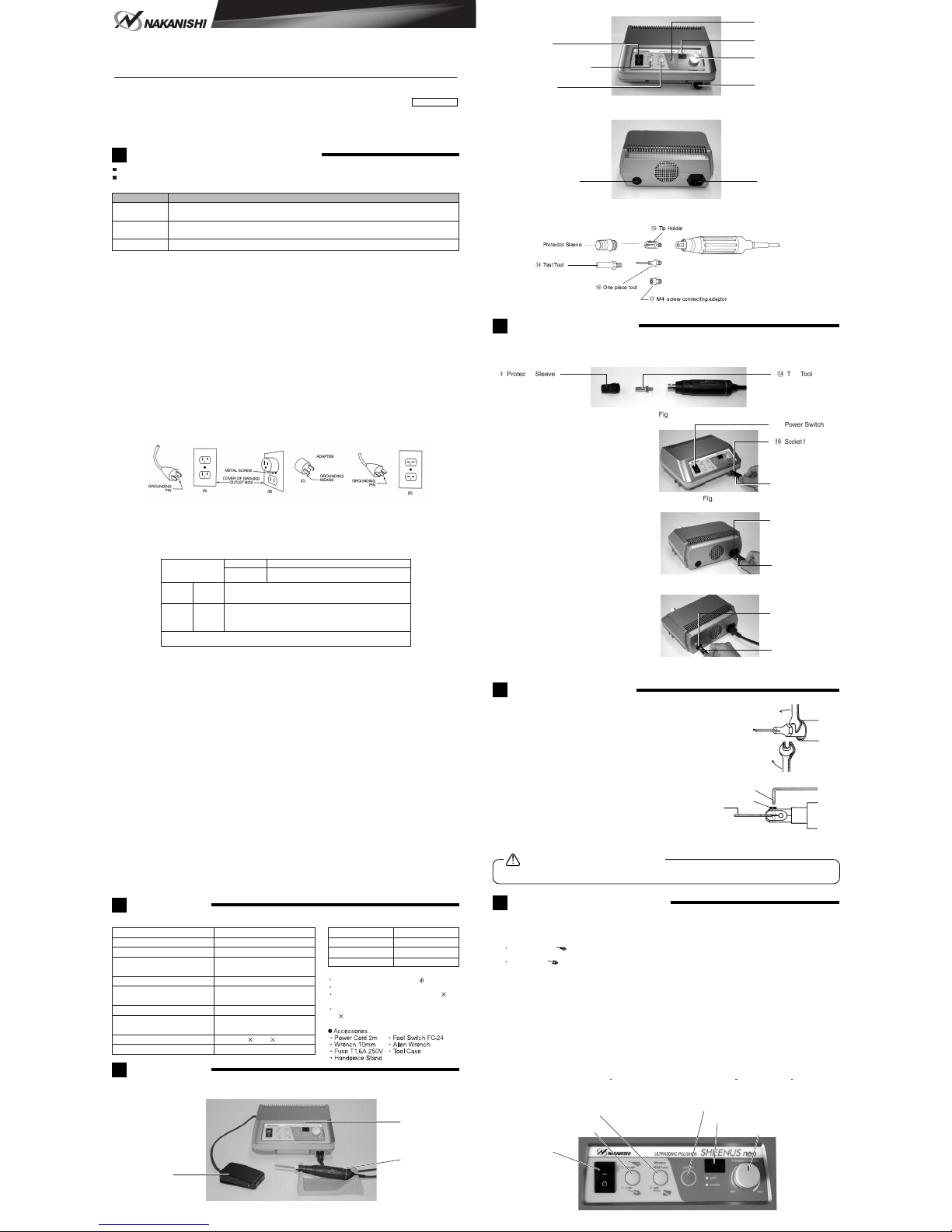
u Display Select Switch
Fig.2
r Power Switch
t UNCLAMP/CLAMP Switch
y ON/OFF Switch
i Display
o Power Control Knob
!0 Socket for connectiong
handpiece
Fig.3
!1 Socket for Foot Switch !2 Power Inlet
Fig.4
!3
!4
!6
!5
!7
Fig.5
!3 Protector Sleeve !4 Test Tool
Fig.6
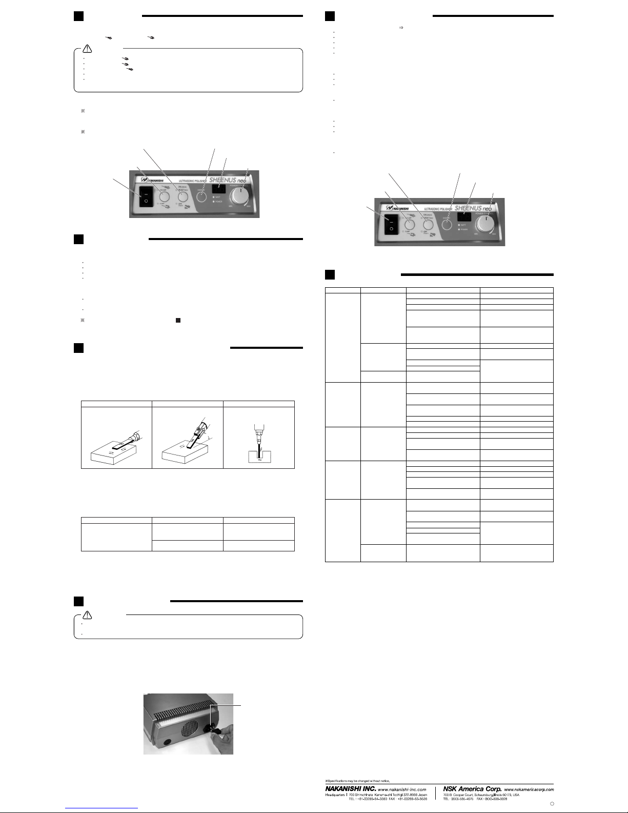
r Power Switch
!0
Socket for connecting
handpiece
Handpiece Plug
Fig.7
!2 Power Inlet
Power Cord
Fig.8
!1 Socket For
Foot Switch
Plug
To The Foot Switch
Fig.9
(2) Front of Sheenus neo
(3) Back of Sheenus neo
(4) Handpiece
(1) The test tool !4 comes with the handpiece. Remove the protector sleeve !3 and unscrew the test tool !4 using the
two provided wrenches. ( The test tool !4 is attached to the handpiece and intended for testing the vibration of the
handpiece.)
(2) Insert the output plug of the handpiece into the
output receptacle !0 of the Sheenus neo.
(3) Make sure that the power switch ris off, and
connect the power cord to the power inlet !2.
(4) When using the foot switch (FC-24), connect the
foot switch plug to the foot switch receptacle !1.
(1) Attachment of one piece holders, tip holders and connecting adaptors
Attach the holder or the connecting adaptor to the handpiece
and clamp tightly using two provided wrenches ( see fig.9).
Then attach the protector sleeve.
(2) Attachment of Tip tools (e.g. ceramic grind stone tip)
Insert the grind stone tip to the tip holder and tighten the screw
using the provided allen wrench. If the clearance between the
groove of the tool holder and the tool is large, do not force put
in a thin metal plate. And attach the protector sleeve.
(3) M4 screw connecting adaptor
Attach the M4 screw connecting adaptor !7 to the handpiece
and clamp tightly using the two provided wrenches. Then
attach the M4 tool and clamp using the wrenches, and attach
the protector sleeve.
If the tool or the tool holder is loose, vibration will be weak and cause noise or overheat.
(1) Power switch r
Turn on/off the power.
(2) Unclamp/Clamp Switch t
There are two modes of Unclamp and Clamp.
Unclamp mode
Use Unclamp mode when one-piece tools are attached.
Clamp mode
Use Clamp mode when a tip holder is attached using unclamp mode for the tip holder may burn and break the
tool due to too much vibration.
(3) On/Off switch y
This is to start or stop the control unit. The On LED lamp (green) is on at start up and during normal operation the
off LED lamp (green) is when shutdown. When the protection circuit stops the control unit, the Reset LED lamp (red)
lights up and the control unit will need to be restarted by pressing the reset button twice after correcting the problem.
(4) Display switch u
By pressing the Display switch, the LED display can be changed from Watt/ Power.
(5) Display i
The selected Watt/Power value is shown on the display.
Watt : Electric power supplied to the oscillator is shown.
The heat generated in the had piece, tool holder and tool is proportional to the power applied to the oscillator,
too much power will cause the handpiec, tool holder and tool to overheat and possibly burn. If the handpiece,
tool holder or tool becomes hot, lower the power setting. USE GREAT CARE TO AVOID TOUCHING THE
TOOL HOLDER AND TOOL DURING WORKING AS THEY CAN CAUSE SEVERE BURNS.
Power : Output level is shown.
Applicable display range is 0 49. (with the test tool, Unclamp mode is 19 49, Clamp mode 8 23.)
(6) Power control knob o
Turn the Power Control knob oto control the output.
Fig.10
Allen Wrench
Set Screw
Tool
Caution on attaching the tool
3Nomenclature
q Foot Switch
(FC-24)
w Control unit
(NE240)
e Handpiece
(US-25PB)
Fig.1
6Detail of the operational parts
Fig.11
y ON/OFF Switch u Display Switch
iDisplay
oPower Control Knob
t UNCLAMP/CLAMP Switch
r Power Switch
Model US-25PB
Oscillator
PZT piezoelectric type
Cord length 2m
Weight
140g(excluding cable)
Unit Model NE240
Oscillation frequency 22.5KHz
Frequency Control Homing Type
Output 45W max.(UNCLAMP MODE)
20W max.(CLAMP MODE)
AC120V, 50/60Hz
AC230V, 50/60Hz
AC120V : T1.6AL 250V
AC230V : T800mAL 250V
Power Conditioning Continuous variable type
Power Source
Rating Input 50VA
Appropriate fuse
Dimensions W225 D195 H97mm
Weight 2.1kg