NanaWall WD66 User manual

Owner’s Manual
NanaWall WD66
Standard Wood Framed Folding System
This Owner’s Manual contains instructions on the installation, operation, maintenance and warranty of
the NanaWall WD66 Standard Wood Framed Folding System. This manual is to be used by the installer
for installation and is to be kept by the Owner for reference. Replacement parts can be ordered directly
through NanaWall Systems.
Nana Wall Systems, Inc.
100 Meadowcreek Drive #250
Corte Madera, CA 94925
800 873 5673
415 383 3148
Fax 415 383 0312
nanawall.com
©2022 Nana Wall Systems, Inc.

NANAWALL WD66 OWNER’S MANUAL
2
Installation Instructions
The installation of the WD66 System requires a working
knowledge and experience in the use of tools, equipment
and methods necessary for the installation of aluminum
doors, windows, storefronts,and/or partitions. This
practice assumes a familiarity with preparing a proper
and structurally sound opening, proper anchorage,
waterproofing, caulking,and sealing and assumes
an understanding of the fundamentals of building
construction that affect the installation of large door
systems.
Highly recommended is using an independent NanaWall
Certified Installer, if available, or, at least, an installer
who has some experience in installing NanaWall
systems.
IMPORTANT: READ COMPLETE INSTRUCTIONS
BEFORE BEGINNING INSTALLATION. INSTALL AS
RECOMMENDED; OTHERWISE, THE UNIT MAY
NOT FUNCTION PROPERLY AND ANY WARRANTY,
WRITTEN OR IMPLIED, WILL BE VOID.
CAUTION:
As regulations governing the use of glazed windows,
doors, storefronts and/or partitions vary widely, it is the
responsibility of the building owner, architect, contractor
or installer to insure that products selected conform to all
applicable codes and regulations, including federal, state,
and local. NanaWall Systems, Inc. can assume no
obligation or responsibility whatsoever for failure of the
building owner, architect, contractor or installer to
comply with all applicable laws and ordinances and
safety and building codes.
The WD66 system is shipped with all necessary
components. However, not included are screws, bolts,
shims, etc. to anchor the unit to the rough opening.
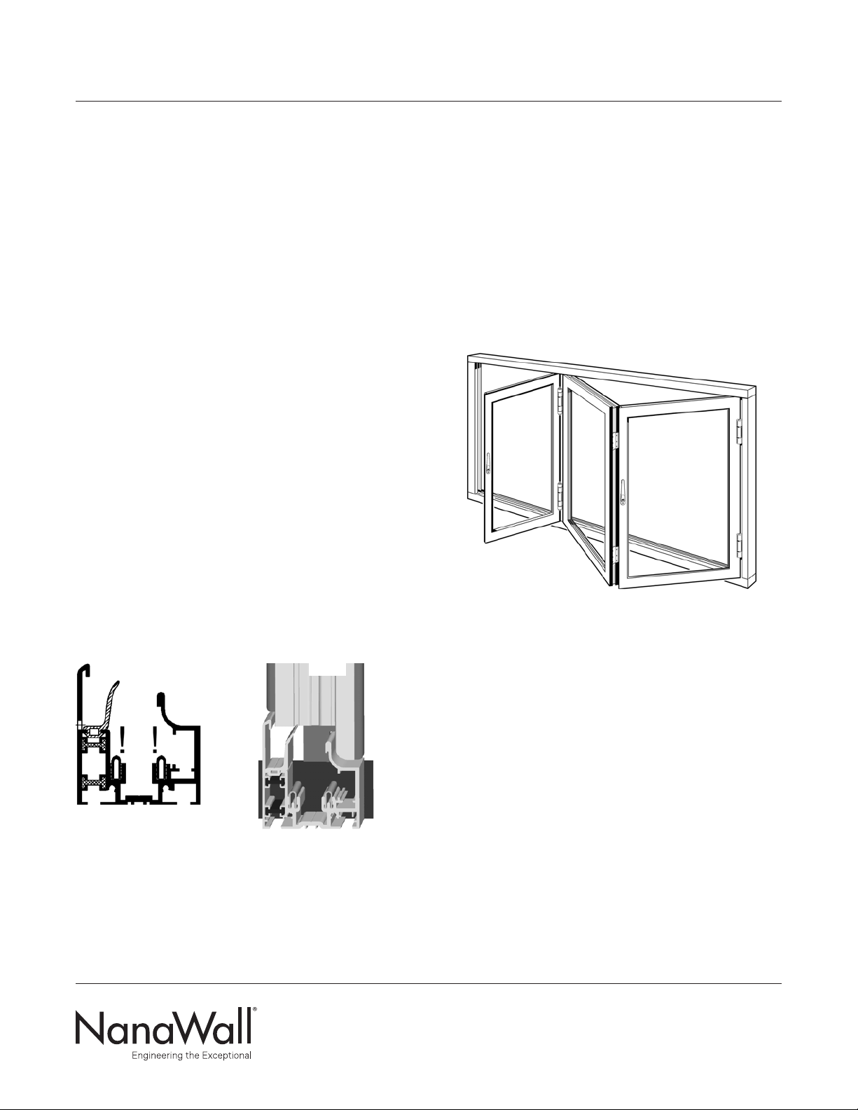
The frame is shipped knocked down and needs to be
assembled. Panels are pre-assembled with or without
glass, ready to be attached to the installed frame. In most
cases, all hinges, weather stripping, multiple locking, and
flat handles are pre-attached to the panels and frame
components.
DESCRIPTION OF SUPPLIED PARTS
Check all parts carefully before assembly. Depending
on the model, some of these parts may already be pre-
installed on the panels. Check that the sizes of the frame
components and panels match with what was ordered.
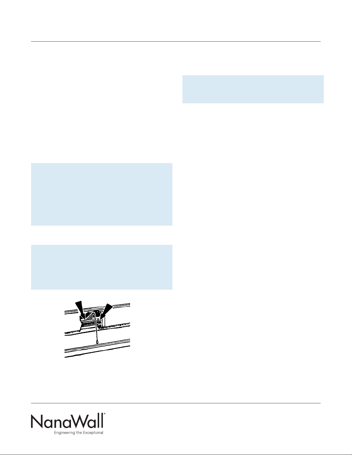
In the cardboard box attached to the frame components
that contains hinge pins and various hardware, inspect
the elevation drawing, indicating size, configuration, and
labeling of the unit ordered. Confirm whether the unit
ordered is WD66/o, top-hung or WD66/u, floor supported.
For orders with multiple units, do not mix and match
panels and frames, even if two units are exactly the same.
Below is a list of supplied parts.
Always looking from inside.
• Left side jamb, labeled L, and right side jamb,
labeled R.
• Head jamb, labeled O, and sill, labeled U. (In some
instances the head jamb and sill may be in segments.)
• Pre-assembled panels, that means locking
mechanism with flat handles are installed on the
panels. The number of panels depends on the model
ordered. The sequence of labeling of panels starts
from the left with the left most panel labeled Panel 1.
If supplied unglazed, panels have to be glazed before
being installed in the opening. See Appendix A: Glass
Installation and Glazing.
• For certain configurations with even number of
panels on a side, separate running posts.

NANAWALL WD66 OWNER’S MANUAL
3
• Upper and lower running carriage sets – one set for
each pair of folding panels. (An extra set for each pair
or multiple pairs of folding panels unhinged to a side
jamb or other panels).
• A certain amount of hinge pins and set screw to
secure the hinge pins.
• Lever handles, other handles or other entry hardware
as ordered. These may be pre-attached to the panels.
• Panel holder – one for each swing door not attached
to a side jamb.
HANDLING OF COMPONENTS
1. Upon receipt, inspect the shipment to ensure it is in
good condition.
2. Make sure that the small cardboard box with the
hinge pins and other hardware does not get lost.
3. Store in a clean and dry location and protect against
defacement or damage, especially to the edges of
panels.
4. Wood components should not be subject to extreme
or rapid changes in heat or humidity, such as forced
heating to dry out a building.
5. All wood surfaces including all edges (top, bottom
and sides) should be completely sealed and finished
promptly.
PREPARATION OF THE ROUGH OPENING
For necessary clearance and adjustment space, make
rough opening about 3/4"wider and 3/8"- 1"higher than
the outside frame size of the unit ordered (check to
comply with applicable codes for maximum shim space
allowed, especially in high windload areas). It is
important that the opening be the correct size. Note that
the outside frame height of the unit ordered is measured
from the bottom of the sill and not from the finished floor.
Allowance must be made in height for the portion of the
sill that is below the measured opening.
IMPORTANT: Because of the large opening sizes
and the weight and movement of the panels, any
application should take into consideration the
following:
1. The structural integrity of the header is critical for
proper operation. Vertical deflection of the header
under full live and dead loads should be the lesser of
L/720th of the span and 1/4". Structural support for
lateral loads (both windload and when the panels are
stacked open) must also be provided.
2. A qualified engineer or architect should be used to
determine the proper construction details and header
to be used in your particular application.
3. THE ROUGH OPENING SHOULD BE LEVEL, PLUMB
AND SQUARE AT ALL POINTS. THERE SHOULD BE
NO UNEVENNESS OR BOWING. MAKE SURE THAT
THE HEADER IS NOT TILTED OR TWISTED. THERE
SHOULD BE NO BUMPS ON THE FLOOR. THE
SIDES SHOULD BE IN THE SAME VERTICAL PLANE
AND NOT OFFSET OF EACH OTHER. A TRANSIT
AND OTHER SIMILAR PRECISE MEASURING
EQUIPMENT SHOULD BE USED.
4. With a recessed sill, if concrete is to be poured after
the installation of the unit, the sill has to be securely
attached to the construction. If the sill is to be cast in
concrete, then an expansion gap with appropriate
material has to be created next to the sill.
5. With a low profile saddle, some resistance to water
infiltration may be achieved by installing drain
connections to the outside. See Diagram 2.

NANAWALL WD66 OWNER’S MANUAL
4
If any anchorage or drain connection holes are made
through these drain channels, make sure that they are
properly sealed to prevent any water leakage. The open
ends of these drain channels at each end of the sill
should also be properly sealed. Alternative anchoring
systems for the sill (without using screws through the
drain channels) are using L brackets attached to both
sides of the sill.
6. For better performance and protection, any exterior
folding system should be installed under an overhang
or with other similar protection.
7. For better performance it is recommended that
all dead loads such as upper levels, roof, etc. be
constructed before a unit is installed.
Properly flash and waterproof around the perimeter
of the opening, especially at the sill. Make sure you
seek proper professional advice for the appropriate
construction needed for your particular application. DO
not install unit in structures that do not allow for proper
management/drainage of moisture.
To avoid future problems, do not install your unit until the
rough opening has been correctly prepared.

NANAWALL WD66 OWNER’S MANUAL
5
WOOD FINISHING AND MAINTENANCE
RECOMMENDATIONS
NanaWall wood framed systems are shipped with a factory
applied layer of a waterborn translucent coat of sand
sealer or primer, which is an acrylic-copolymer-dispersion
from Sikkens (www.nam.sikkens.com). NanaWall aluminum
clad wood framed systems are shipped with a similar
additional coat. These factory applied coatings are not a
suicient and adequate protection from the elements and
at least two coats of a final finish need to be applied in
the field.
IMPORTANT: Immediately upon receipt of the unit
and prior to installation and exterior exposure to
weather elements, all wood surfaces including all
edges (top, bottom and sides) should be
completely sealed and must be protected with a
good quality finish. Before installation, keep the
units in a dry and clean location, store,and stack
them properly to avoid twisting or warping of the
panels and frame components.
To complete the wood surface treatment use compatible
finish material. If you think the product that you are
intending to use is not compatible, then completely
remove all pre-applied coats by chemical stripping
(please follow the direction of the product) or by sanding
o. Do not use power wash or excessive water. Then apply
a good quality sealer or primer and continue applying the
necessary coats as recommended by the product you
have chosen.
CAUTION:
Not all available paints and stains, nor the customer’s
specific application requirements can be evaluated. Your
local paint professional should know of suitable finish
systems that give satisfactory results in your region. It is
highly recommended that top quality finishes be selected,
and the directions of the products be followed explicitly.
In general, the surface must be prepared by cleaning o
dust and any debris. With 180-220 grit sandpaper, sand
lightly and thoroughly all surfaces to be painted. Do not
use steel wool or silicon carbide type sandpapers. Then
clean the surfaces before applying paint, etc.
For best performance, a minimum of two topcoats should
be applied.
Always make sure that you apply the coatings on a
hidden area before finishing the whole unit to make sure
you are satisfied with the results.
Ensure not to apply the coating material on to hardware,
gaskets, glass, sealant,or aluminum surfaces to maintain
proper product performance.
All damages or scratches during installation on the
surface coating should be immediately touched up.
WOOD SIMULATED DIVIDED LITES SDL
It is recommend that after completing the surface
treatment of the SDL and after allowing for adequate
drying time, to seal the gaps between the SDL and glass
with a durable weather resistant caulking material, which
is compatible with the surface treatment material.
MAINTENANCE OF WOOD UNITS
As a general guideline it is recommended that every
1/2 year or earlier, to inspect visually the surface
and if necessary re-finish in the same manner as
per instructions above. The timeframe may vary on
weathering, exposure conditions and altitude. Whenever
damage is visual, it should be repaired immediately.

NANAWALL WD66 OWNER’S MANUAL
6
UNIT INSTALLATION
The Installation of the folding unit is described in the
following categories:
A. FRAME ASSEMBLY AND INSTALLATION
B. PANELS AND FOLDING HARDWARE INSTALLATION
C. FINAL STEPS
A. FRAME ASSEMBLY AND INSTALLATION
It might be easier to drill the holes as described in
Step A8 before assembling the frame.
Step A1
Lay the four frame components flat on the floor and
align the ends to be joined. If the head jamb and sill are
provided in segments, then connect them first. Make sure
that the frame components are in the correct positions.
The frame should be labeled U for sill, O for head jamb,
and looking from inside, R for right side jamb and L for
left side jamb. Note: If there are no weep holes in the sill,
please check whether such holes are required and drill
them if necessary. Please be careful to avoid scratching or
damaging the components.
Step A2
Make sure that the stainless steel insert for the sill of
floor supported WD66/u are in the correct place
(Illustration A1).
Step A3
For top-hung WD66/o L/R with unhinged pairs of panels
not connected to a side jamb, see Step B7. The upper
running carriage has to be inserted in the head track
before assembling the frame.
Step A4
Assemble all frame parts as shown. Do not apply sealant
to the corner joints yet.
DIAGRAM 1: WD66 EXAMPLE OF A 3 PANEL UNIT
INWARD OPENING
Step A5
Do not screw the vertical side jambs to the head track nor
the sill. It has to be possible to slide the side jamb inwards
or outwards for adjustment.
Step A6
Be sure that appropriate flashing around the perimeter
of the opening is installed. Set the assembled frame into
the rough opening at the proper position relative to the
header. Make sure the direction is correct with respect to
inward or outward opening.
See Diagram 2 for Suggested Installation Details. Please
note that these are suggestions only and that these may
not be suitable in all applications.
Step A7
Temporarily secure the frame to the rough opening with
clamps.
L, R
U
ILL. A1 ILL. A2
U
R
O
L

NANAWALL WD66 OWNER’S MANUAL
7
DIAGRAM 2: WD66 SUGGESTED TYPICAL INSTALLATION
Suggested Typical Installation drawings shown are very general and may not be suitable
for any particular installation. Product placement, fasteners, flashing, waterproofing,
sealant, trim,and other details for specific surrounding conditions must be properly
designed and provided by others.
Drawings not to scale.
Details shown are subject to
change without notice.
INWARD OPENING DETAILS OUTWARD OPENING DETAILS
TOPHUNG HEAD JAMB
Inward Opening Panel Hinged at Right Side
Jamb for Top-Hung and Floor Supported
Outward Opening Panel Hinged at Right Side
Jamb for Top-Hung and Floor Supported
TOPHUNG HEAD JAMB FLOOR SUPPORTED HEAD JAMB
TOPHUNG RAISED SILL TOPHUNG RAISED SILL
FLOOR SUPPORTED RAISED SILL

NANAWALL WD66 OWNER’S MANUAL
8
Step A8
Looking on a standard installation, which is limited to
areas with a basic wind speed of not more than 90 mph,
in a low rise building (max. 60 feet roof height),
Exposures B or C and a non critical status. Fasteners
locations should start about 4"from the interior edge, drill
holes for the anchorage devices to connect the frame to
the opening at a spacing of not more than every 16"
along the head jamb and the sill. On the head jamb and
sill an additional fastener should be placed at the
meeting point of panels in the closed position and
anchorage points every 4"in the stacking area on either
side. The spacing of the side jamb should be about 14"
starting at the bottom, using an extra screw at the top.
For installation that are beyond the above limitations, a
structural engineer should be consulted for specific
fastening requirements. For Florida installations, please
see Appendix B for specific installation requirements.
Use appropriate screws or other equivalent anchorage
devices depending on the adjacent substrate material
and construction. Make sure they are corrosion resistant.
Anchorage devices should penetrate or hold sufficiently
INWARD AND OUTWARD OPENING DETAILS
DIAGRAM 2: WD66 SUGGESTED TYPICAL INSTALLATION
Suggested Typical Installation drawings shown are very general and may not be suitable
for any particular installation. Product placement, fasteners, flashing, waterproofing,
sealant, trim,and other details for specific surrounding conditions must be properly
designed and provided by others.
Drawings not to scale.
Details shown are subject
to change without notice.
Note: Contact us for
detailed information.
TOP-HUNG LOW PROFILE SADDLE SILL
For resistance against wind driven rain,
recommend the following by others:
1. Remove the gasket covering the inner
water channel.
2. Provide necessary weep holes at
bottom of channel and through to the
outside face of the sill.
3. Make necessary drain connections.
To adjust for
dierence in floor
levels, sill flange
is bendable or
removable (in the
field).
TOP-HUNG FLUSH SILL
(no rating against wind driven rain)
FLOOR SUPPORTED FLUSH SILL
(no rating against wind driven rain)

NANAWALL WD66 OWNER’S MANUAL
9
Make sure that the frame is level, plumb and square at
all points. There should be no unevenness or bowing.
If, for any reason, the floor is not level, shim with plastic
horseshoe shims to the highest point of the floor,
provided there is still enough clearance at the top. Place
plastic, horseshoe type shims tightly at every fixing point
between the frame profile and rough opening. Use hard
plastic horseshoe shims only.
Step A9
For the top-hung WD66/o and for the floor supported
WD66/u anchor the sill to the subfloor.
The sill has to be installed in correct relation to the finish
floor. Make sure that the sill is not tilted or twisted. Make
sure that all holes drilled through the sill are properly
sealed with silicone underneath and around the screws.
All weep holes in the sill are not to be obstructed.
Make any necessary adjustments to level, plumb, and
square before proceeding on.
to the opening to withstand necessary structural loading.
Generally, for wood frame use #14 (1/4"diameter) wood
screws with 2-1/2"minimum embedment, for concrete with
a minimum compressive strength of 3,200 psi use 3/16"
diameter ITW Tapcons (concrete screws) with 1-1/4"min.
embedment. For masonry use 1/4"diameter ITW Tapcons
(masonry screws) with 1-1/4"embedment. Standard
installation into light gage steel substrates with a
minimum of 18 gage (0.0451"thick) should have 1/4"
diameter type 410 stainless steel self drilling screws. Into
structural steel substrates thicker than 1/4"should be pre
drilled and 1/4"diameter SAE Grade 2 bolts can be used.
Another option is to use type 410 stainless steel self
drilling screws. For this option first drill small pilot holes.
Make sure that the screw head with washer (if any) is
small enough to fit inside the slot in the middle of the
head jamb and sill; otherwise, it will interfere with the
rolling of the running carriages.
Anchor through the center of the groove but make
sure the screw or bolt head with washer bears on the
aluminum. To maintain the thermal break, use PVC or
nylon washers so that the screw heads do not bridge the
aluminum.
DIAGRAM 3:
SUGGESTED FRAME FASTENING POINTS
A = About 4"from the interior edge.
B = Distance about 16", except at the stacking area on
one or both sides where spacing should be about 4".
Plus extra screws at meeting point of panels.
C = Distance about 14"from the bottom using extra
screw at top.
See Appendix B for Florida installations.

NANAWALL WD66 OWNER’S MANUAL
10
Step A10
Anchor the side jambs to studs or walls. Make sure that
the jambs are plumb and straight.
Be aware that the anchorage points in the side jamb with
the lesser number of panels attached to it may in Step C6
need to be loosened to be able to move the side jamb to
adjust the total width of the unit.
Step A11
As the sill is attached first, then the side jambs, now
anchor the head jamb through the pre-drilled holes and
shims. Make sure that the head jamb is level.
IMPORTANT: Make sure no shims are forced to
ensure that frame sections are not bowed. Check
frame constantly to be certain that it is level, plumb,
and square. A transit and other similar precise
measuring equipment should be used to make these
determinations.
Step A12
IMPORTANT: Make sure that all the surfaces of the
upper and lower tracks are clean and free of any
debris, especially, cuttings from drilled holes. See
Illustration A3.
B. PANELS AND FOLDING HARDWARE
INSTALLATION
IMPORTANT: Look for glass stops to determine the
interior side of a panel.
Step B1
On top-hung WD66/o insert all the upper running
carriages into the upper track, through the slot on
one end of the head jamb. The lower running carriage
functions as a guide in the sill. See also Diagram 2.
On floor supported WD66/u insert all lower running
carriages into the sill. See Illustration B1. The upper
running carriage is just a guide in the upper track. See
also Diagram 2.
Step B2
Looking at the elevation drawing, first install panel(s)
hinged to the side jamb(s). Align the hinge components
on the panel to the hinge components on the side jamb
and insert the proper hinge pin. Insert the hinge pin in a
way such that the security set screw fit into the groove in
the hinge pin. Loosen the set screw as needed to insert
the hinge pin, tighten till it touch the pin and then back o
a full turn. Use an Allen key. See Illustration B2.
ILL. A3

NANAWALL WD66 OWNER’S MANUAL
11
Step B3
Again, looking at the elevation drawing, attach the next
panel needed to create a folding pair by aligning the
hinges and inserting the proper hinge pins. If necessary,
place temporary blocks under the panels to assist in
keeping the panels in a steady position. These two panels
are connected with hinges according to Illustration B2.
Step B4
Close the folding pair by turning the handle 180°.
Step B5
Locking at the elevation drawing, now the upper and
lower running carriage should be attached. Therefore
they have to be inserted in the upper and lower track as
described above under step B1.
In general the upper and lower running carriage enfold
the hinge and the provided long screws with the self-
locking nut secures the assembly. See also Illustration B3.
Step B6
Attach the next panel to this folding pair by demounting
the long screw of the running carriage that way that the
hinge part of the next panel can be safety inserted into
this assembly.
Step B7
For a running post at the end of a sequence of even
number of panels or for unhinged paired panels, the upper
and the lower carriage are pre-attached to the running
post.
Step B8
Complete the assembling of the upper and lower running
carriage as shown in Illustration B3. Secure the long screw
with the self-locking nut in such a way that between 1
and 2 full treads are showing through. Do not over tight,
because this aects the operation. Here the security set
screw is not needed. Insert the proper hinge pins on the
remaining hinges.
Step B9
Attach additional panels in the same manner.
After installation of each panel, check to make sure that
the panel is vertically straight.
ILL. B1 ILL. B2 ILL. B3

NANAWALL WD66 OWNER’S MANUAL
12
C. FINAL STEPS
Step C1
Attach handles and other hardware that have not been
pre-attached. Attach the profile cylinder (if any) to the
locking gear by inserting it into the lock hole and
attaching the set screw through the screw hole on the
gear located at the edge of the panel. Cut the set screw,
if needed, so it is not longer than 1-1/2"to 2"depending
on locking type.
Step C2
IMPORTANT: For swing panels not attached to a
side jamb, attach the panel catch to the stile with the
handle and the catch counter-part to the opposite stile
of the adjacent panel. Follow the specific instructions
that are on the sheet in the panel catch kit. The
purpose of this is that the swing panel should always
be opened and engaged into the panel catch before
the folding panels are to be opened.
Step C3
Close and lock all panels into position.
Step C4
Check all horizontal joints:
Make sure the head jamb and sill are still level. Then
along the entire width of the opening, check the spacing
between the head jamb and each panel should be about
5/16"along the entire length of the unit. Check especially
to see if the upper corner of a panel where the running
carriage is located is not higher than the other corner of
the panel. If it is slightly lower (not more than 1/16"), it is
okay. Then along the entire width of the opening, check
the spacing between the sill and each panel, which
should be about 3/8"along the entire length of the unit.
Proper spacing is critical for proper operation of the
unit.
Step C5
Check all vertical joints:
Make sure that the side jambs are still vertically straight.
All vertical spacing between side jamb & panel rebate and
the join where swing panel meet swing panel should be
5/16", spacing between panel & panel and panel & running
post should be about 1/2".
Step C6
If the spacing on the vertical joints are not correct,
adjustments can be made by moving the side jamb(s)
as needed.
Step C7
Various adjustments can be made by adjusting the hinges
and running carriages to correct some minor spacing and
operational problems. Adjustments are complex and if
not performed properly, may make matters worse. Only a
trained installer or with proper guidance from NanaWall
should any adjustments be attempted. Please contact
NanaWall.
Step C8
Check that the system operates and functions properly.
The panels should be able to be moved easily by one
person without much eort (for not more than 6 panels
to one side) when opening or closing and all shoot bolts
should engage smoothly. If the panels do not move easily
or a lot of eort is needed, the indication is that the unit is
not properly installed. Correct any problems before finish
trimming.

NANAWALL WD66 OWNER’S MANUAL
13
Step C9
Seal the joints [A] on the exterior between the vertical
jamb and the sill with exterior grade sealant. Therefore lift
the gasket, re-install and glue it afterwards. Also fill the
space [B] underneath the vertical frame and the sill with
exterior grade sealant generous to avoid water leakage
into the wall and to protect the wood. See Illustration C1.
ILL. C1: SEALING THE SILL
Step C10
Apply a thick bead of exterior grade sealant with a backer
rod if needed on the joint between the sill and sub floor
on both sides along the length of the sill. Do similar for
the gaps between the head jamb and side jambs with the
opening.
Step C11
Finish any waterproofing, flashing, trim and sealant
needed around the perimeter of the opening.
Important: Make sure any weep holes in the sill are
not blocked.
Step C12
To prevent uncontrolled movement of the panels when in
open position, place appropriate door holder by others
as needed.
PROTECTION OF UNIT DURING
CONSTRUCTION PHASE
It is important that during the construction phase
the unit be kept closed, covered and protected from
damage. During this phase, a unit is often subject to the
most extreme conditions from all types of construction
operations that can permanently damage and destroy
it. A unit can be damaged by cement splatter, tar, paint,
weld splatter, falling objects, construction dust, sand
blasting, etc. All temptations to use the large opening
of an installed system for easy ingress and egress by
tradesmen should be resisted.
A
B
U
B
L, R

NANAWALL WD66 OWNER’S MANUAL
14
Operation And Maintenance
Of NanaWall Products
OPERATION OF A NANAWALL FOLDING UNIT
For opening and closing the folding system, please
observe the special notes on the following pages in as far
as they relate to your folding system.
When operating the folding system similar to
any other door, please do not place your fingers
between the panels/pivot points. You may hurt
them!
Do not have anyone not properly trained on operation
and children operate the unit.
Do not force the system if not operating properly.
Please have it repaired as soon as possible by a qualified
technician.
Anchor panels when in the open position to prevent
uncontrolled movement, especially in windy conditions,
that might cause damage and injury.
It is highly recommended that if not used, the NanaWall
folding unit be kept closed as much as possible, in order
to provide best security and weather resistance. When
closed, please engage all locking mechanisms fully.
The correct sequence of opening and closing of panels is
dependent on the configuration ordered. Panels must be
opened and closed in the right order.
With a Swing Panel Attached to a Folding Pair
1. Open the swing panel a full 180° and connect to the
panel catch on the adjacent panel.
2. Disengage the locking points on all the other panels.
3. Slide folding panels, starting with the pair adjacent to
the swing panel.
For closing, proceed in reverse order.
Without a Swing Panel
1. Disengage locking points on primary opening panel
pair and fold it slightly.
2. Do the same with any adjacent panel pair.
3. Slide folding panels completely to the side.
For closing, proceed in reverse order.
With Unhinged Paired Panels and No Swing Panel
1. Disengage locking points on primary opening panel
pair and fold it slightly.
2. Do the same with any adjacent panel pair (s).
3. Slide folding panels into desired stacking position.
For closing,proceed in reverse order.
1
1
2 2 3
3
2
1
23
1
1
2 2 3
3
2
1
23
1
1
2 2 3
3
2
1
23

NANAWALL WD66 OWNER’S MANUAL
15
OPERATING THE SLMULTIPOINT LOCKING ON THE PRIMARY SWING PANEL
Engaging the locking points and locking
• Turn handle up about 45° to engage the locking points. Then let it move back into its normal position.
• Only now can it be locked with a key on the outside or a thumb turn on the inside.
Unlock and disengaging the locking points
• Unlock the lock with key or thumb turn.
• By operating the door handle downwards, the locking points at the top and the bottom are disengaged.
UNLOCKING
(Note that this is not one
motion operation. Key
or thumbturn must be
unlocked first.)
LOCKING
Be sure to check that the door is locked.
The door is locked, when the handle
cannot be depressed.
Normal position Engaging Locking Unlocking Disengaging locking points

NANAWALL WD66 OWNER’S MANUAL
16
RECOMMENDED MAINTENANCE OF
NANAWALL PRODUCTS
Some General Considerations on all Projects:
1. It is important that the product is installed correctly.
A poorly installed unit will not function properly.
This will cause more abnormal force or stress on
the components and will lead to premature failure.
When operating the unit, the panels should generally
be able to be moved easily by one person (except
when there are very large panels or when there are
more than 6 panels folding to one side). All locking
points should engage smoothly. There should be no
rubbing on the floor and no binding. When the unit is
closed, the reveal between panels and head jamb and
between panels and sill should be consistent. There
should be no daylight seen from the inside. Please
have all problems corrected as soon as possible by a
qualified technician.
2. From time to time, due to building movement or
settlement, a unit may need to be adjusted by a
qualified technician to compensate for any building
change.
3. It is important that a unit is operated properly.
Locking points should be gently opened and closed
and not forced. Panels should be opened and
closed in the proper manner and sequence. See the
Operation section for proper operation.
4. Periodically check for worn or damaged components
and replace as soon as possible. A unit with
nonworking components will subject the other
components to increased stress and lead to
premature failure. A unit with worn or damaged
components will compromise the performance level
expected for air and water infiltration, structural
loading and forced entry.
5. Periodically, inspect the sealant/caulking on the
exterior perimeter of the unit. It is extremely
important that the sealant/caulking remains intact
and in good condition. Trim o any old, loose caulking
and seal any gaps with a good quality caulk.
6. Check that all weep holes are clean and clear of any
obstructions. Remove debris and other foreign bodies
which have dropped into the tracks in the head jamb
and sill immediately to prevent damaging the running
carriages and guide trolleys. Clean all components as
needed.
Check gaskets for proper seating and condition.
Remove dust and any deposits from these gaskets.
7. The finished aluminum or wood surface needs
periodic cleaning and maintenance. Its appearance
may be marred by harsh chemicals, abuse or neglect.
Frequency of cleaning depends on exposure and
needs. For aluminum surfaces, generally warm
soapy water should be suicient. Stubborn stains
and deposits may be removed with mineral spirits.
For wood surfaces, superficial surface dirt can be
removed by washing with water and a soft-bristled,
long-handled brush. Heavier accumulations can
be removed with a mild solution of household
detergent. For all surfaces, aggressive alkaline or
acid cleaners should not be used. Excessive abrasive
rubbing should be avoided. Sealants and weather
stripping may be aected by strong organic solvents.
Superficial damage to the aluminum surface must be
touched up immediately with proper touch up paint.
8. If it is a wood product, the surface should be visually
inspected every six months or earlier, depending
on the exposure of the NanaWall unit. Periodically
repaint or restain the wood as needed. Exposure
to the environment will break down the finish and
compromise its protective features if not refinished.

NANAWALL WD66 OWNER’S MANUAL
17
See Finishing Recommendations in the Owner’s
Manual of the wood systems.
9. All hardware, hinges and handles should be
periodically cleaned with a soft cloth and mild
cleanser. Excessive abrasive rubbing should be
avoided. Please note that oil rubbed brass is a finish
that will develop its own unique patina over time.
10. About every six months, apply lubricant to all the
hinges and Teflon spray to the running carriages and
guiding trolleys.
SOME SPECIFIC SUGGESTED MAINTENANCE
FOR COASTAL SALT WATER AND OTHER
EXTREME ENVIRONMENTS:
Please note that the environment within one mile of a
sea coast can be extremely corrosive. Products installed
in this environment will typically deteriorate sooner than
products installed in a less severe environment.
1. Open and close completely a unit at least once a
week and inspect all surfaces.
a. Salt and other corrosive or abrasive materials
such as sand must not be allowed to build up on
any surfaces, including all hardware and sill.
b. The sill and head jamb tracks should be free from
all dirt and debris.
c. There should be no standing water in the track
in the sill.
d. All hardware should be intact and operating
properly.
2. All surfaces must be cleaned with a mild detergent
soap and fresh water at least every month and more
frequently if necessary.
a. After washing, the surface should be rinsed
thoroughly with clean water and allowed to dry.
b. For cleaning, do not use abrasive household
cleaners or materials like steel wool or hard
brushes that can wear and harm finishes.
c. Any glass cleaner used should not be allowed to
run down on any other surface.
3. Any breaches in the paint coating, such as scratches,
chips or areas of abrasion, must be repaired
immediately.
4. Every 3 months, thoroughly clean and dry all upper
and lower rollers and all hinges. Liberally apply
lubricant such as Teflon spray (no grease) on the
wheels and bearings of the rollers. Oil all hinges
including the hinge pin with light weight lubricating
oil or Teflon spray.
5. As with any painted surface exposed to corrosive
environments, every 6 months apply a wax to the
outside of the painted panel and painted track. If the
system includes corner connections make sure the
wax penetrates the connection joints.

18
APPENDIX A NANAWALL WD66 OWNER’S MANUAL
GLASS INSTALLATION AND GLAZING
This section applies only if you need to install glass for
any reason or if glass setting blocks need to be adjusted.
Proper glass installation is critical, as, with the NanaWall
folding system, glass is a structural part of the panel.
Glass stops and glazing gasket are to be used for “dry”
glazing of each panel. Also needed are setting blocks.
Use glass setting blocks with varying thickness made
from hard plastic. Rubber setting blocks are not
acceptable. Width of setting blocks should be at least 1/8"
wider than the glass thickness and 1/16"to 1/8"less than
the width of the glazing pocket.
Glass, with appropriate dimensions, thickness and
specifications will be needed. Depending on the model,
widths of all glass panels may not be equal. Please note
that glass is required to be fully tempered unless the unit
is a window placed above a certain height from the floor.
Check with all applicable codes and regulations.
Float glass, including the glass components of insulated
glass, shall meet the current requirements of ASTM C
1306 “Standard Specifications for Flat Glass” for quality,
thickness and dimensional tolerances. Tempered float
glass shall meet the current requirements of ASTM C
1048 “Standard Specifications for Heat-Treated Flat
Glass - Kind HS, Kind FT Coated and Uncoated Glass.”
All tempered glass shall have a permanent logo, which
signifies Safety Commission 16 CFR-1201 and the safety
glass test requirements of ANSI Z 97.1 (current editions).
Insulating Glass shall meet the requirements of ASTM E
774, Class A, B or C.
Although glass installation with the “dry” glazing system
is relatively straight forward, it is recommended that an
experienced glazing contractor be used.
It is very important that the bracing direction and
placement of glass setting blocks on opposite diagonal
corners be correct. Setting blocks are to be placed only
at opposite diagonal corners with corners alternating with
each succeeding panel. This is necessary for the stability
and balance of the panels when in operation. If not
correctly braced, the unit will not operate properly.
The general rules for bracing are as follows:
• For a panel attached to a side jamb, the lower brace
should be at the lower corner closest to the side.
• For a panel with a running carriage, the lower brace
should be on the lower corner that is on the same
side as the running carriage.
• For a swing panel, the lower brace should be at the
lower corner away from the stile with the locking
hardware. See Diagram 1 for an example of setting
block locations.
Follow all proper applicable glass installation and glazing
techniques as recommended in the Flat Glass Marketing
Association (FGMA) “Glazing Manual” and “Sealant
Manual”. Always use suction cups to shift glass within an
opening. It would be best to install the glass on the panels
before they are installed in the opening. Panels can be laid
flat on sawhorses. If the panels are already installed, they
can still be glazed.
1. Close all panels and secure them with the multiple
point lock bolts. Start with a panel that is attached to
a side jamb or, in the case of unhinged pairs, closest
to a side jamb.
2. Remove all glass stops on the panel. Be sure to
protect the finish.

19
APPENDIX A NANAWALL WD66 OWNER’S MANUAL
3.Measure both the vertical and horizontal dimensions
of the glass and the panel opening. Subtract the
vertical glass size from the vertical panel opening size.
Divide the difference by two. This will give the nominal
thickness of the setting block to use at the top and
bottom rails. Several setting blocks of different
thickness may need to be combined to obtain the
desired thickness. Do the same for the horizontal
dimension to obtain the thickness of the setting block
to use at the stiles.
4. Place a setting block (or combination of setting
blocks with desired thickness) on the bottom rail of
the panel opening such that it is about 2"from
the bottom corner as determined by the bracing rules
above.
5. Carefully place the glass in the opening, making sure
it rests on the setting block. With insulated glass,
make sure that both inner and outer panes are
supported evenly.
6. Place a second setting block in the same corner as
the first setting block, but in the vertical direction
along the stile such that it is about 2"above the
corner.
7. Place another setting block in the upper diagonal
corner vertically on the opposite stile in the same
manner. If necessary, apply a little adhesive that is
non-damaging to the glass edge seals such as Dow
Corning 791 silicone, to keep the vertical setting
blocks from slipping.
8. Place the last setting block on the upper rail on the
same corner as the other upper setting block. To get a
proper fit, shift the glass weight by lifting the panel up
with a plastic pry bar at the lower corner below the
upper setting block. These setting blocks should all fit
snugly but should not be forced.
Adjust the thickness of the glass setting blocks such
that the panel is slightly out of square. The upper
corner with the setting blocks should be about 1/16"
higher than the other corner.
If the panels are large, additional setting blocks may
be needed midpoint on the stiles, especially on a
swing panel.
9. For aluminum systems insert the glass stops so that
they snap into the panel profile. For wood systems
insert the glass stop firmly into position, so they are
flush with the panel. Nail to the inner side of the panel
with small finish nails. Start with the top and bottom
stops and then the sides.
10. Insert the glazing gasket in the space between the
glass and the glass stop. First, cut the gasket to a
length a little longer than the actual length of the
glass stop because gasket material may shrink at low
temperatures. Do not stretch or pull the gasket in any
manner. If necessary, use soapy water to lubricate the
gasket to make insertion easier.
11. Make sure that the stops are locked firmly and
securely into position and are flush with the rest of
the panel profile.
12. Repeat Steps 2 to 12 for each of the other panels.
Setting blocks for each succeeding panel must be
placed at diagonally opposite corners in the proper
sequence as set forth in Step 1. See Diagram 1 for an
example of a three panel unit.
13. After installing the panels, assuming that the head
jamb and sill are level, check to see if the gap
between the panel and head jamb and panel and sill
is even across the width of the panel. With the glass
weight, the out of square panels should become
almost even. If they remain slightly higher in the

20
APPENDIX A NANAWALL WD66 OWNER’S MANUAL
upper corner with the setting blocks it is okay. If not,
then the lower and upper setting blocks thickness
need to be adjusted. Panels have to be braced
correctly for proper operation.
DIAGRAM 1:
Setting blocks for tension
Setting blocks to keep distance
Bracing Direction
Bracing Direction
Bracing Direction
Setting blocks for tension
Setting blocks to keep distance
Bracing Direction
Bracing Direction
Bracing Direction
Table of contents
Other NanaWall Folding Machine manuals