NANO 2 Series Manual

MAINTENANCE & SERVICE MANUAL
www.n-psi.com
BREATHING AIR PURIFIER
SERIES 2

Document Issued Created Checked Revision
17-110-0491 05/11/2015 N.McFall B.Ausn 0

CONTENTS
CHAPTER TITLE PAGE(S)
1General Informaon 4
1.1 Document introducon 4
1.2 Support & Manufacturing details 4
1.3 General Safety 5
1.4 Warranty guidelines 5
1.5 Packaging 5
2 Service Intervals 6
3 Product Assembly / NBA-070, 090 7
3.1 NBA-110, 120 8
4 Recommended Tools 9
5 Dryer Shutdown Procedure 9
6 Maintenance Guidelines 9
7 Service ‘A’ Desiccant cartridge replacement 10
8 Service ‘B’ Outlet valve replacement 11-12
9 Service ‘B’ Inlet & exhaust valve replacement 13-14
10 Service ‘B’ Exhaust valve replacement 15
11 Service ‘B’ Inlet pilot control valve replacement 16-17
12 Service ‘C’ Dewpoint sensor replacement 18-19
13 Reseng dryer control 20
14 Manifold ghtening sequences 21
15 Dryer start up procedure 22
16 Other dryer checks & non- serviceable items 23
17 Troubleshoong 24
18 Service record & notes 25-26

Page 4
1. GENERAL INFORMATION
This manual is copyrighted, all rights reserved. It may not, in whole or in part, be copied, photocopied, reproduced,
translated, or reduced to any electronic medium or machine readable form without prior consent in wring from
nano-puricaon soluons. It may not be distributed through the internet or computer bullen board systems
without prior consent from nano-puricaon soluons limited.
1.2 Support and Manufacturers Details
NOTES: highlight important secons of informaon where parcular care and aenon should be paid.
CAUTIONS: indicate any situaon or operaon that may result in potenal damage to the product,
injury to the user, or render the product unsafe.
Annotaons:
1.1 Document Introducon
This manual provides factory prescribed installaon and maintenance procedures for a nano-puricaon soluons
Series 2 Breathing air dryer. The procedures illustrated in this document are only to be performed by fully trained
competent authorized personnel. For further informaon regarding the procedures outlined in this document
contact nano-puricaon soluons before proceeding.
Read this document carefully before aempng to install or operate the dryer. This document should be
permanently available at the dryer installaon site and be kept in an easily accessible place alongside the dryer.
©2015 nano-puricaon soluons ltd.
Product: Series 2 - Breathing Air Purier
Models: NBA-070, 090, 110, 120.
Doc no: 17-110-0491
Issue: 001
nano-purication solutions
11330 Vanstory Drive
Huntersville, NC 28078
USA
Telephone: (704) 897-2182
Fax: (704) 897-2183
Internet: www.n-psi.com
E-mail: [email protected]

Page 5
1.4 Warranty Guidelines
All products are supplied with a 2 year manufacturer’s warranty from the date of purchase, when purchased with
or without an ES (Energy Saving) system when installed and maintained in accordance with the manufacturers
guidelines. Only genuine service parts should be used and no modicaons made. For further informaon please
contact nano-puricaon soluons.
1.5 Packaging
All dryers are securely packaged in a bespoke moulded packing system. The dryer module will be secured in a
horizontal posion using two specically moulded support cushions.
The support packing box permits limited longitudinal stacking; however the central secon of the
packing box should not be considered load bearing.
Damage to Packaging
• Check immediately to establish whether damage has occurred to the external packaging and if the damage
extends to the product inside.
• If there is damage to a product, contact the relevant supplier immediately.
In no circumstances must a damaged product be used in operaon. Using damaged products can lead
to irreparable funconal faults or cause serious physical harm.
1.3 General Safety
For your own safety, when carrying out maintenance work on the dryer, all relevant naonal safety regulaons must be
complied with relang to pressurized and electrical systems. Only authorized, competent and trained personnel should
maintain the dryer, this user guide is intended solely for such personnel and is to be used only as a reference, it should
not be used to replace convenonal training.
NOTE: highlight important secons of informaon where parcular care and aenon should be paid.
CAUTIONS: indicate any situaon or operaon that may result in potenal damage to the product,
injury to the user, or render the product unsafe.

Page 6
The following table details the recommended service intervals for this product and the service kits to be used.
2. SERVICE INTERVALS
SERVICE
TYPE
RECOMMENDED SERVICE INTERVALS
1 Year (6000 Hrs) 2 Years (12000 Hrs) 4 Years (24000 Hrs)
AP P P
BP
C P
DRYER
MODEL
REQUIRED SERVICE KITS
Service B Service C Service D
NBA-070 NBK-060 NVK-090 (EVK-130 & CVK-130 & IVK-090)
NBA-090 NBK-080 NVK-090 (EVK-130 & CVK-130 & IVK-090)
NBA-110 NBK-110 NVK-130 (EVK-130 & CVK-130 & PVK-130)
NBA-120 NBK-120 NVK-130 (EVK-130 & CVK-130 & PVK-130)
ALL ES NSK-130
SERVICE
TYPE
ADDITIONAL FOR ES MODELS ONLY
ANNUALLY
DP
SERVICE A
Replace all external lter elements (pre and post lters)
Please contact an n-psi represenve for lter servicing informaon.

Page 7
3. PRODUCT ASSEMBLY
TOP COVER
INLET/OUTLET (TOP)
MANIFOLD
ASSEMBLY
DESICCANT
CARTRIDGES
DRYER
CONTROLLER
DRYER
SHROUD
DRYER
COLUMN
BOTTOM
MANIFOLD
ASSEMBLY
DRYER LEGS
SILENCER
BOX
EXHAUST VALVE
INLET VALVE
MODELS: NBA-070, 090

Page 8
3.1 PRODUCT ASSEMBLY MODELS: NBA-110, 120
TOP COVER
OUTLET (TOP)
MANIFOLD
ASSEMBLY
DESICCANT
CARTRIDGES
DRYER
CONTROLLER
DRYER
COLUMN
INLET (BOTTOM)
MANIFOLD
ASSEMBLY
DRYER LEGS
SILENCER
BOX
DRYER
SHROUD
EXHAUST VALVE
VALVE
BLOCK
INLET
BLOCK

Page 9
4. RECOMMENDED TOOLS
The following tools will be required to service the dryer:
5. DRYER SHUT DOWN PROCEDURE
Before performing any maintenance or service operaons on this product, ensure the product is isolat-
ed from the compressed air supply and fully depressurized. Also ensure the product is switched o and
isolated from the mains power.
PROCEDURES
The dryer might sll be pressurized! In order to depressurize the dryer; ensure the dryer is isolated from the com-
pressed air source:
o Close the inlet and outlet valves
o Cycle the dryer twice to ensure the dryer exhausts and is completely depressurized.
o When fully depressurized the ‘clicking’ of the exhaust valves will be heard but no air
exhausted.
• When the dryer is fully depressurized, isolate from the power supply.
TERMINAL SCREW DRIVER
ALLEN KEY 3mm
ALLEN KEY 4mm
ALLEN KEY 6mm
ALLEN KEY 8mm
TORQUE WRENCH (8-60NM)
TORQUE SOCKET 6mm/10mm
20mm PIN SPANNER
VALVE EXTRACTION TOOL
INTERNAL CIRCLIP PLIERS
MAGNET (for re-seng controller)
PETROLEUM JELLY (VASOLINE)
6. MAINTENANCE GUIDELINES
• Maintenance operaons only to be conducted when the system has been shut down and fully
depressurized.
• All connecons must be undone with care, paying parcular aenon to the areas that become
pressurized.
• Do not modify or adjust the control sengs.
• Only cered nano-porous soluons approved replacement parts to be used.
Always check all connecons for leakage and secure seang before operaon.
Ensure all loose parts removed during maintenance are reed correctly before operaon.

Page 10
7. SERVICE ‘A’ INSTRUCTIONS
(Every 6,000 hrs or 12 months)
1. Ensure the dryer is shutdown and
fully depressurized before aempng any
maintenance work.
Refer to: CH. 6.MAINTENANCE GUIDELINES
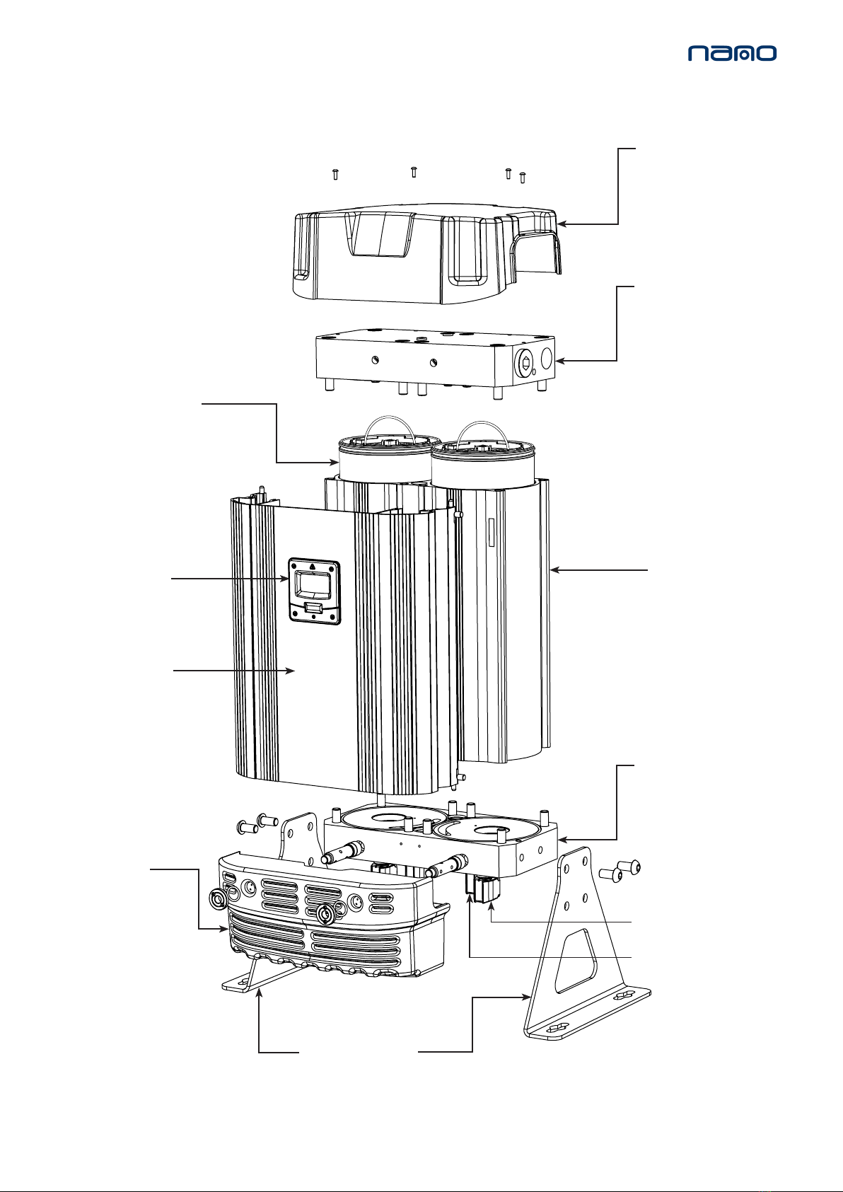
2. Remove the 4x M5 screws as shown to
remove the dryer top cover.
3. Remove the 8x M12 cap head screws and 8x
washers to remove the top manifold from the
dryer column and support front shroud.
4. Discard the gasket seal.
5. Li the wire handle and remove the
cartridge from the dryer column.
6. Check and clean the top manifold and dryer
column as required, paying parcular aenon to
the gasket sealing faces.
7. Remove the new cartridges and gasket seal
from the service kit provided.
8. Insert 2x new desiccant cartridges and press
them down unl they stop and the cartridge is
below the top surface of the dryer column.
9. Insert the new gasket seal placing it into the
gasket groove in the top manifold ensuring it is
fully retained.
10. Ensure both handles are folded at.
11. Replace the top manifold and secure with the
8x M12 cap head screws ghtening to a torque
seng of 80Nm.
NOTE: Refer to:
CH.
14. MANIFOLD TIGHTENING SEQUENCES
and
follow the correct ghtening sequence.
12. The seal between the dryer column and top
manifold should be checked for leaks prior to
ng the top cover and operang the dryer.
13. Replace the dryer top cover and secure with
the 4x M5 screws. These screws should be hand
ghtened only or ghtened to a torque seng of
less than 1Nm.
If service A is complete reset the dryer,
Refer to: NOTE: Care must be taken when removing the
desiccant cartridges not to damage the top face of
the dryer column. This is a sealing face!
(Sealing face shown as the shaded area)
GASKET SEAL
TOP MANIFOLD
8x M12 CAP HEAD
SCREWS
TOP COVER
DESICCANT CARTRIDGES
4x M5 SCREWS
MODELS: NBA-070, 090, 110, 120
DESICCANT CARTRIDGE REPLACEMENT
NBK-060, 080, 110, 120
Figure 1.
CH. 13. RESETTING DRYER CONTROLLER

Page 11
8x M12 CAP HEAD
SCREWS
TOP
MANIFOLD
(Every 24,000 hrs or 4 Years)
8. SERVICE ‘B’ INSTRUCTIONS
OUTLET VALVE REPLACEMENT
Please refer to gure 1
1. Ensure the dryer is shutdown and fully depressurized before aempng any maintenance work.
Refer to: CH. 6.MAINTENANCE GUIDELINES
2. Remove the 4x M5 screws to remove the dryer top cover.
3. Remove the 8x M12 cap head screws and 8x washers to remove the top manifold from the dryer column and
support front shroud.
4. Using a pair of circlip pliers, remove each circlip.
CIRCLIP
VALVE SEAT
CHECK VALVE
DU BUSH
MODELS: NBA- 070, 090, 110, 120
CVK-130
Figure 1.
GASKET SEAL

Page 12
5. Remove the valve seat by inserng the valve extracon tool through the middle of the seat valve, resng the narrow
end of the tool on the dome point of the check valve.
6. Rotate the thread of the tool, moving the plate aached to it and forcing the check vale out of the valve orice
within the outlet manifold.
7. Once the valve seat is removed, remove the check valve by hand.
8. Remove the DU bush and replace it from the NVK-CHK service kit.
9. Replace the check valve rstly from the service kit, then secondly replace valve seat.
10. Replace the circlip from the service kit.
11. Replace he seal between the dryer column and top manifold.
12. Place the manifold back on top of the dryer column and insert the 8x M12 cap head screws and 8x washers and
ghten at a torque seng of 80Nm.
NOTE: Refer to CH. 14. MANIFOLD TIGHTENING SEQUENCES and follow the correct ghtening sequence.
13. Replace the top cover and insert the 4x M5 screws to secure it in place. Hand ghten these screws only or ghten
to a torque seng of less than 1Nm
.
When service B is complete reset the dryer, Refer to:
12
34
Figure 2.
CH. 13. RESETTING DRYER CONTROLLER

Page 13
INLET AND EXHAUST VALVE REPLACEMENT
Figure 1.
2. Detach each of the solenoid plugs
from the solenoid coils by removing
the 4x plug screws and releasing
the plugs.
(See gure 1)
SOLENOID
PLUG
PLUG
SCREW
3. Remove the solenoid coils
by unclipping and sliding the
coils from the valve stems.
(See gures 2 & 3)
Figure 2.
RETAINING CLIP
SOLENOIDS
COILS
VALVE
STEM
1. Ensure the dryer is shutdown and
fully depressurized before aempt-
ing any maintenance work.
Refer to
CH.
6.MAINTENANCE GUIDELINES
IVK-090 & EVK-130 & CVK-130
(Every 24,000 hrs or 4 Years)
9. SERVICE ‘B’ INSTRUCTIONS
(REAR VIEW OF DRYER)
Figure 3.
MODELS: NBA-070, 090

Page 14
VALVE
DIAPHRAGM
EXHAUST
VALVE
BODIES
M5 SOCKET HEAD
SCREWS
Figure 4.
4. Remove the 16x M5 socket head screws and the 16x spring washers and discard them. Remove and
discard the valve bodies from the boom manifold. (See gure 4)
5. Remove and discard the 4x diaphragms from the boom manifold. (See gure 4)
6. Replace the 4x diaphragms and 4x valves from the service kit and replace the 16x M5 socket head screws and spring
washers from the service kit and ghten to a torque seng of 6Nm. (See gure 4)
7. Reaach the 4x solenoid coils and 4x solenoid plugs. (See gure 1)
When service B is complete reset the dryer.
Refer to:
BOTTOM
MANIFOLD
NOTE: correct valve screw
ghtening sequence shown.
3 2
4
1
CH. 13. RESETTING DRYER CONTROLLER

Page 15
(Every 24,000 hrs or 4 Years
EXHAUST VALVE REPLACEMENT
O RING
VALVE DIAPHRAGM
EXHAUST VALVE BODIES
SILENCER
FIXING NUT
M5 SOCKET HEAD
SCREWS
3. Remove the 8x M5 socket head
screws and the 8x spring washers and
remove the exhaust valve
bodies and diaphragms from the inlet
(boom) manifold.
(See Figure 2)
4. Replace the 2x diaphragms and 2x
exhaust valves from the service kit.
5.Replace the 8x M5 socket head
screws and spring washers and ghten
at a torque seng of 6Nm. Reaach
the 2x solenoid valves and 2x plugs.
(See Figure 2)
10. SERVICE ‘B’ INSTRUCTIONS MODELS: NBA- 110, 120
CVK-130 & EVK-130 & PVK-130
Figure 1.
Figure 2.
3 2
4
1
NOTE: correct valve screw
ghtening sequence shown.
1. Ensure the dryer is shutdown and
fully depressurized before aempt-
ing any maintenance work.
Refer to
CH.
6.MAINTENANCE GUIDELINES.
2. Unscrew the silencer xing nut using
a 20mm pin spanner and remove the
O ring to release the silencer box from
the assembly.
(See Figure 1)
SILENCER
BOX

Page 16
11. SERVICE ‘B’ INSTRUCTIONS
INLET PILOT CONTROL VALVE REPLACEMENT
CVK-130 & EVK-130 & PVK-130
MODELS: NBA- 110, 120
(Every 24,000 hrs or 4 Years)
2. Detach solenoid plugs from
solenoid coils by removing the
2x plug screws and releasing
plugs.
(See gure 1)
1. Ensure dryer is shutdown and fully
depressurized before maintenance
work.
Refer to:
CH. 6.MAINTENANCE GUIDELINES.
3. Detach inlet valve tubes 1,2,3 from block.
(See gure 2)
4. Remove Inlet valve mount bracket screws
2x (M3x 12) and detach bracket assy from
dryer.
(See gure 3)
Figure 1.
Figure 2.
Figure 3.
NOTE: Label tubes when
removing manifold.
1
2
3

Page 17
1. Replace 2x valves.
2. Re-t 2x elbows, 1x tee.
3. Re-t 2x blanking plugs.
4. Re-t valves to bracket.
5. Re-t valve bracket assy to dryer.
6. Aach inlet valve tubes to block.
7. Aach solenoid plugs to solenoid coils.
8. Re-t Silencer box (refer to 10:2)
6. Remove 2x elbows, 1x tee,
2x blanking plugs from valves.
(See gure 5)
Assemble opposite to
dis- asssembly as follows:
5. Remove 6x (M3x30) screws, nuts, washers
and detach valves from bracket.
(See gure 4)
Figure 4.
Figure 5.

Page 18
M4 SCREWS
12. SERVICE ‘C’ INSTRUCTIONS
(Every 6,000 hrs or 12 months) Figure 1.
2. Loosen the 4x M5 screws to remove the
top cover. (See Figure 1)
4. Remove the screw from the sensor plug
and detach it from the dew point sensor
assembly. (See Figure 3 & 4)
SENSOR
PLUG
SCREW
SENSOR
PLUG
CONTROLLER
CHASSIS PLATE
1. Ensure the dryer is shutdown and
fully depressurized before aempng any
maintenance work.
Refer to:
CH. 6.MAINTENANCE GUIDELINES.
3. Release the catches located at the top and
boom of the shroud to open it.
(See Figure’s 1 & 2)
ES MODELS ONLY
DEWPOINT SENSOR REPLACEMENT
NSK-130
Figure 3.
Figure 4.
Figure 2.

Page 19
Figure 7.
6. Unscrew the dew point sensor from the sensor block and
replace with the new or re-calibrated sensor. (See Figure 7)
7. Reaach the new or re-calibrated dew point sensor and sensor block
assembly to the controller chassis plate using the 2x xing screws.
8. Replace the sensor plug and screw to complete the sensor assembly.
(See Figure 3 & 4)
9. Close the shroud and ensure the latches are in posion.
10. Replace the top cover and insert the 4x M5 screws. These screws
should be hand ghtened only. (See Figure 1)
DEW POINT SENSOR
SENSOR BLOCK
Figure 5.
5. Remove the 2x xing screws from the controller chassis plate and
release the dew point sensor assembly. (See Figure 5 & 6)
When service C is complete reset the dryer, refer to:
Figure 6.
NOTE: Allow sensor to stabilize, this may take several hours.
CH. 13. RESETTING DRYER CONTROLLER

Page 20
13. RESETTING DRYER CONTROLLER
CONTROLLER
RESET AREA
1. Ensure the dryer is on and running, Refer to: CH. 15. DRYER START-UP PROCEDURE
2. Place a magnet over the controller reset area shown in Figure 1 for 8-10 seconds unl the
dryer re-sets. (See Figure 1)
3. Once re-set the hours run counter will show ‘00000’.
NOTE: Magnet not included in the service kit.
Figure 1.
This manual suits for next models
4
Table of contents
Other NANO Air Cleaner manuals
Popular Air Cleaner manuals by other brands

Gree
Gree SP-240A Operation manual

Fresh-Aire UV
Fresh-Aire UV COMMERCIAL Series Installation & maintenance

Honeywell
Honeywell 18155 owner's manual

Soleus Air
Soleus Air AH1-CC-01 operating instructions

Perenio
Perenio IONIC SHIELD PEWOW01COV Installation and operation manual

asecos
asecos PURIFIAIR.620 operating manual