NanoSurface Cytostretcher-LV User manual

NanoSurface Cytostretcher-LV
Cell Stretching Instrument with Nanopatterned Chambers
User Manual
Last Revised 5 October 2018
(HWrCSLV2.0)
Copyright ã2018
NanoSurface Biomedical, Inc.
4000 Mason Road, Suite 304
Seattle, WA 98195
United States of America
www.nanosurfacebio.com
+1-800-913-4403

NanoSurface Cytostretcher Operation Manual ã2018 NanoSurface Biomedical, Inc.
2
INTRODUCTION ....................................................................................................................................3
SECTION 1: SYSTEM OVERVIEW........................................................................................................4
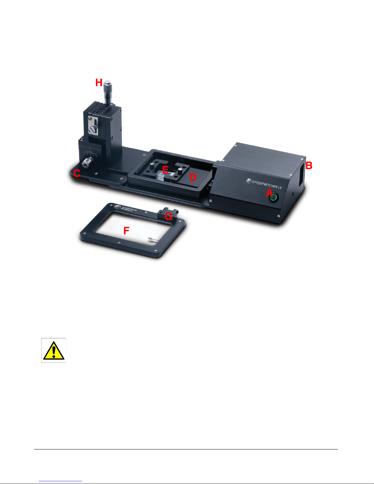
A. THE NANOSURFACE CYTOSTRETCHER-LV ............................................................................................................ 4
B. REMOVING THE GLASS WINDOW ....................................................................................................................... 5
C. CYTOSTRETCHER CULTURE CHAMBER ...................................................................................................................... 6
Two Chamber Sizes ......................................................................................................................................... 6
Two Surface Options for Each Chamber Size .................................................................................................. 6
D. SOFTWARE ......................................................................................................................................................... 6
SECTION 2: USING THE CYTOSTRETCHER ......................................................................................7
A. PREPARATION OF THE CYTOSTRETCHER .................................................................................................................... 7
B. SOFTWARE INSTALLATION ..................................................................................................................................... 7
C. FOCUS TILT ADJUSTMENT ................................................................................................................................. 8
Procedure ........................................................................................................................................................ 8
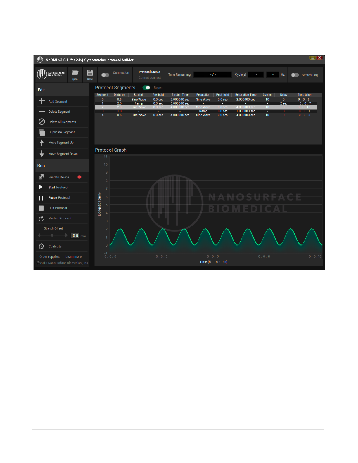
D. SOFTWARE OPERATION .................................................................................................................................... 9
Overview: ........................................................................................................................................................ 9
Before starting: ............................................................................................................................................. 10
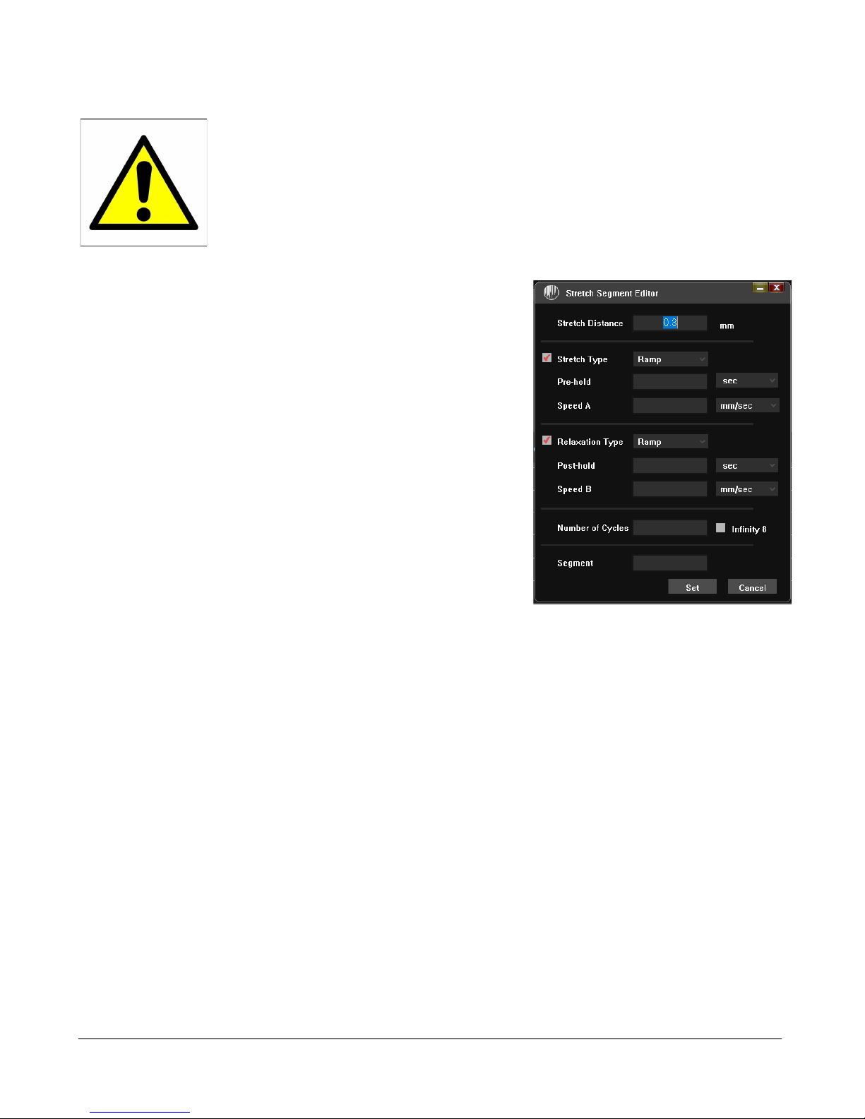
Working with Stretch Segments .................................................................................................................... 10
Offsets: .......................................................................................................................................................... 10
Calibration: ................................................................................................................................................... 10
Example- Symmetrical Repetitive Sine Stretch with no fixed time: 10%, 1Hz using a 12 mm chamber. ....... 11
Calculating Strain .......................................................................................................................................... 11
SECTION 3: CULTURING CELLS IN THE CYTOSTRETCHER CHAMBERS ...................................12
A. CHAMBER STERILIZATION .................................................................................................................................... 12
B. CELL ATTACHMENT ............................................................................................................................................ 12
Plasma Treatment (Recommended) ............................................................................................................. 12
Coating with ECM proteins without plasma treatment ................................................................................ 12
Chemical Modification .................................................................................................................................. 13
SECTION 4: WARRANTY & SPECIFICATIONS ................................................................................. 14
WARRANTY .......................................................................................................................................................... 14
SPECIFICATIONS ..................................................................................................................................................... 14
APPENDIX A: INSTALLING THE FONT PACKAGE ..........................................................................15
REFERENCES .....................................................................................................................................16

NanoSurface Cytostretcher Operation Manual ã2018 NanoSurface Biomedical, Inc.
3
Introduction
Thank you for purchasing the NanoSurface Cytostretcher-LV. This device is designed to stretch NanoSurface’s
proprietary in vitro culture chambers on top of an inverted optical microscope.
The Cytostrecher-LV is compatible with NanoSurface Biomedical’s Environmental Control Unit (ECU). The ECU
is an optional accessory that controls the temperature and CO2content of the environment inside the imaging
chamber. Operation of the ECU is covered in a separate manual. If you need to add the ECU accessory to your
Cytostretcher-LV, please email [email protected] or your local distributor.
Please read this manual thoroughly. It contains important information to ensure safe and proper use of the
instrument. Critical information that could result in injury to you or in damage to the instrument will be highlighted
with a warning triangle. Do not ignore these important warnings!
This manual and the product described herein is subject to change. Changes to the product may not be accurately
reflected in this manual. Images of the product may not be identical to the latest shipping product. If there are any
questions, please contact us.
**This product is intended for research use only**
Please follow the instructions in this manual carefully. Failure to do
so could result in injury to the user or damage to the instrument.
There are no user serviceable parts inside the Cytostretcher-LV.
Opening the Cytostretcher-LV case or removing mechanical
components could result in damage to the instrument. Opening the
Cytostretcher-LV will immediately void the warranty. For service,
email [email protected] or call +1-800-913-4403.

NanoSurface Cytostretcher Operation Manual ã2018 NanoSurface Biomedical, Inc.
4
Section 1: System Overview
A. The NanoSurface Cytostretcher-LV
A. Control button: pause and resume stretch. Hold this button to turn your Cytostretcher on and off.
B. AC power port and USB communication cable port.
C. Offset/Pre-tension thumbscrew: allows you to pre-stretch the membrane, if desired.
D. Actuating Bracket: this component holds part of the chamber and moves back and forth to provide stretch.
The actuating bracket moves back and forth when the Cytostretcher is
operating. Keep objects and fingers clear of this bracket, as it can result
in injury to the user or damage to the Cytostretcher.
E. Chamber: Location of the chamber
F. Imaging Chamber Cover: removable glass window for maintaining chamber CO2and Temperature control with
the optional ECU.
G. Cover Connector: Magnetic connector to interface with the optional ECU.
H. Z Focus Shift Micrometer: adjusts the Z-plane of the chamber as it stretches in order to maintain focus under
stretch.

NanoSurface Cytostretcher Operation Manual ã2018 NanoSurface Biomedical, Inc.
5
The following features are shown on the image below:
I. Standard Universal Type-K microscope mount (inquire about other styles)
J. Glass window
B. Removing the Glass Window
If the glass window needs to be removed or replaced, you can access it by removing the four bolts that hold the
window frame in place (Figure A, below). After removing the bolts, gently lift the glass out with a small tool or pair
of tweezers (Figure B, below). If the window is beyond cleaning or damaged, please contact

NanoSurface Cytostretcher Operation Manual ã2018 NanoSurface Biomedical, Inc.
6
C. Cytostretcher Culture Chamber
Two Chamber Sizes
The NanoSurface Cytostretcher is designed to work with NanoSurface’s small and medium-sized cell culture
chambers. They are not compatible with the large (50 x 50 mm) chambers. Compatible chambers are available in
two sizes. The small chamber has a 25 mm2culture area in a square well that measures 5 x 5 mm. The medium
chamber has a total culture area of 144 mm2, in a square well that measures 12 x 12 mm. Dimensional details are
presented in the figure below. The chamber material is silicone based and can be prepared for cell culture using
standard coating techniques. Additional information about treatment with ECM proteins is noted in a subsequent
section of this manual.
To mount the chamber, insert the included stainless-steel rods through the round holes in the sides of the chamber.
Use these rods to mount the chamber into the Cytostretcher.
Two Surface Options for Each Chamber Size
All of the Cytostretcher chambers come with either flat (unpatterned control; left image) or nanopatterned (center
image) surfaces. For the nanopatterned surfaces, the horizontal parts of the ridges and the grooves are both 800
nm. The depth of the grooves is 600 nm. See Figure 1 for details.
Figure 1. Left: A scanning electron micrograph of the unpatterned surface. Center: A scanning electron
micrograph of the nanopattern showing the surface and cross section. Right: A schematic showing the
approximate dimensions of the nanopattern cross-section.
D. Software
The Cytostretcher is controlled by NanoSurface Operational Mechanics Interface (NaOMI). Please email
contact@nanosurfacebio.com for the latest version. NaOMI will run on either a PC or a Mac. Operation of the
software will be detailed in the next section.

NanoSurface Cytostretcher Operation Manual ã2018 NanoSurface Biomedical, Inc.
7
Section 2: Using the Cytostretcher
A. Preparation of the Cytostretcher
1- Before using the Cytostretcher, it is recommended that you sterilize it. We recommend wiping the unit
down with 70% ethanol and ultrapure water. Avoid getting liquid into the power or USB ports. Ensure that
the unit is dry before connecting the power or USB cables. Note that the inner motors and electronics are
sealed from liquid intrusion but using excessive amounts of liquid or immersing parts of the Cytostretcher
will damage the instrument.
2- Sterilize and coat the chamber as described in Section 3.
3- Connect the power cable to the Cytostretcher and plug in to the power source. The Cytostretcher will begin
calibration and get ready for stretching. Note that many cell culture incubators have ports located on the
back wall; many of our customers choose to route their USB and power cables through this port.
B. Software Installation
Important Note: NanoSurface’s NaOMI software requires the use of the “Roboto” font/typeface. If your system
does not already have this installed, please see Appendix A for instructions. If this is not installed on your computer,
the software window will not display properly, and some buttons may be missing.
1- Step 1: Download the software
a. NanoSurface’s NaOMI software is made to work on Windows 10. For the latest software version,
please contact [email protected]
b. The software will be a ZIP file. De-compress this. You will see two folders: one for the USB driver,
and one for the Software.
2- Step 2: Install the USB Driver
a. The Cytostretcher requires a specific USB driver. The driver is included with the ZIP archive that
contains the software. You can also download it here: http://www.ftdichip.com/Drivers/D2XX.htm
b. This driver will not affect other devices attached to your computer.
c. The driver is in the “Cytostretcher USB driver” folder.
d. Once the driver is installed, restart your computer.
3- Step 3: Install NaOMI (Cytostretcher Software)
a. Double-click the Setup icon.
b. Depending on your windows security settings, you may have a warning that this software is from
an unverified publisher. Simply override this warning to continue installation.
c. Proceed with the installation. The installer should leave a shortcut on your desktop.

NanoSurface Cytostretcher Operation Manual ã2018 NanoSurface Biomedical, Inc.
8
C. Focus Tilt Adjustment
NanoSurface recommends adjusting the angle of the Cytostretcher chamber to ensure that the pre-stretch and
post-stretch states remain in the same focal plane. This is accomplished by adjusting the four M3-hex head bolts
located adjacent to the chamber rods. To ensure cell viability, this can be performed before cells are cultured on
to the chamber. Note that different chambers may require individual adjustment.
Procedure
1. Start with the test chamber that shipped with your instrument. If the test chamber does not have ink markings
on the surface, use a sharpie to deposit some ink on the cell culture surface.
2. Load the chamber into the Cytostretcher-LV. Make sure you clamp the rods down with the thumbscrews.
3. Turn the Z focus adjust micrometer until the adjustment stage is at its lowest position. You should be able
to look at the chamber and see that the left side is lower than the right.
4. Using the NaOMI software, program a stretch routine that has the same amount of stretch that you plan to
use. Program a cyclical stretch with a delay of a few seconds in between stretch and relax. This delay should
be long enough to allow you to focus the optical microscope between stretch-and relax phases.
5. Use the microscope to focus on the surface of the chamber. The edges of the inkblot can be helpful focusing
targets.
6. Start the stretch routine.
7. When the sample is fully stretched, you will have to adjust the microscope focus knob to keep the sample in
focus.
8. Iteratively adjust the Z micrometer in steps while re-checking focus. You may not see a big difference in how
much you need to focus even after several Z adjustments.
9. Over several adjustment cycles you will find that the focus positions become much closer to each other; at
this point continue the iterative adjustment with smaller steps until the focus at stretch versus relaxation is
the same.
10. Replace the test chamber with your sample. You may have to make some minor adjustments with the Z
micrometer to maintain exact focus.

NanoSurface Cytostretcher Operation Manual ã2018 NanoSurface Biomedical, Inc.
9
D. Software Operation
Overview:
The Cytostretcher is controlled by the NanoSurface Operational Mechanics Interface (NaOMI). NaOMI
allows you to design a particular stretch protocol and run the instrument. The instrument does not need
to be connected to the computer during the actual stretch protocol, but you will need to connect to the
instrument via USB in order to program it with your protocol. Once the protocol has been sent to the
instrument, it no longer needs to be connected to the computer.
Protocols are built as a series of steps or “Stretch Segment”. Your protocol can be one or many Stretch
Segments. Stretch Segments are added, removed, duplicated, or re-ordered under the “Edit” section on
the left of the panel. Each Stretch Segment will appear as a line in the “Protocol Segments” window.
Double-clicking the Stretch Segment will open up the “Stretch Segment Editor” window, which enables
you to change various aspects of the stretch.
Once a protocol is built, the graph at the bottom of the software window will show you an approximate
representation of stretch vs. time.
When you are happy with your protocol, you will send it to the device before starting.

NanoSurface Cytostretcher Operation Manual ã2018 NanoSurface Biomedical, Inc.
10
Before starting:
Do not load your chamber into the instrument until you are ready to stretch.
Before loading the chamber, power on the instrument. Connect to the Cytostretcher
by pressing the “NaOMI Connection” button. Re-set the zero point of the instrument
by pressing the “Calibrate” button. Set your program and send it to the instrument.
Each of these steps may result in an actuation of the device. After doing this, load
your chamber.
Working with Stretch Segments
Each Stretch Segment has its own parameters. Double-clicking
the segment will open the Stretch Segment Editor (image on the
right). This is where you will change the segment parameters.
• First, define the amount of stretch (“Stretch distance”).
The table below shows you how distance relates to %
stretch.
• You can define whether the Cytostretcher will stretch with
a linear (“ramp”) or sinusoidal (“sine”) waveform under
the “Stretch Type” parameter.
• If you like, you can apply a “pre-hold”, which is a pause
that is made before the stretch is applied.
• Last, you can define the speed at which the stretch is
made (“Speed A”).
If you’d like an asymmetrical stretch, where the relaxation has different parameters, check the box next
to “relaxation type”.
• The waveform of the relaxation type can be set to Ramp or Sine
• a “post-hold” time can be added- this will be a holding time between the maximum stretch and
the onset of relaxation. if you do not want any delay between stretch and relax, set this to “0”.
• Specify the speed of relaxation in the “Speed B” parameter.
Offsets:
This can be used to pre-tension your chamber. The offset will be used as the starting point for any stretching
routines, and all stretch distances will be relative to the offset point. You can adjust this by pressing the arrow
buttons or moving the slider.
Calibration:
This button re-sets the zero point of the stretcher. NanoSurface recommends calibrating the instrument before
each use. Note that pressing this button will actuate the stretcher. If any cells are in the device, they will be
stretched to a potentially dangerous degree.

NanoSurface Cytostretcher Operation Manual ã2018 NanoSurface Biomedical, Inc.
11
Example- Symmetrical Repetitive Sine Stretch with no fixed time: 10%, 1Hz using a 12 mm chamber.
1- Launch NaOMI
2- Connect to the Cytostretcher.
3- Press the “calibrate” button.
4- Add a new Stretch Segment by clicking the “+ Add Segment” button on the left side of the window.
5- Input your stretch distance (1.2 mm).
6- Select “Sine” for Stretch Type.
7- Set pre- and post-hold to zero.
8- Set speed to 2.4 mm/sec (one full stretch-relax cycle per second).
9- Make sure that the “relaxation type” box is not checked (this will ensure that the stretch is symmetrical).
10- Check “Infinity” (this removes any limits on the number of cycles)
11- Set “Segment” to zero.
12- Send the protocol to the device by pressing “Send to device”
13- wait until the indicator on the software panel turns green.
14- Load your chamber
15- press the ‘Start Protocol’ button or the physical button on the Cytostretcher controller.
Calculating Strain
The amount of strain is a function of chamber size and total actuation.
To calculate overall strain, use the following formula:
(Stretch Distance / Chamber Length) X 100 = % Strain
The Cytostretcher-LV is compatible with chambers that have a 5 mm length (Small chamber) or a 12 mm length
(medium chamber). So, for example, applying 1.2 mm of stretch to a 12 mm chamber, you get:
(1.2 mm Stretch Distance / 12 mm Chamber Length) X 100 = 10% Strain
Alternatively, if you have a % strain that you want, use the following formula to obtain the stretch distance:
(Desired Strain Percentage / 100) X Chamber Length = Stretch Distance
For example, to get a 15% stretch distance on a 12 mm medium chamber, you get:
(15 Desired Strain Percentage / 100 ) X 12 mm chamber length = 1.8 mm Stretch Distance
A table of some commonly used stretch percentages are listed below.
Table: Percent Stretch and Stretch Distances for various chamber sizes:

NanoSurface Cytostretcher Operation Manual ã2018 NanoSurface Biomedical, Inc.
12
Section 3: Culturing Cells in the Cytostretcher Chambers
A. Chamber Sterilization
The Cytostretcher chambers are made of medical-grade silicone. These silicones are common in many
biomedical applications, including human implantation, cell culture and microfluidics.
Before using the chambers, it is recommended that you sterilize them. This can be accomplished by autoclaving
the chambers or by briefly submerging the chambers in 70% ethanol:water (sonication recommended), followed
by rinsing with ultrapure and sterile water, then drying in a sterile cell culture hood or under vacuum.
B. Cell Attachment
Silicone elastomers are usually hydrophobic. This means that they can be very difficult to wet, making cell
culture and pre-treatment with proteins difficult. There are a few ways to approach this problem1:
Plasma Treatment (Recommended)
Plasma treatment involves exposing the silicone chambers to a high-energy plasma. This is normally done using
a dedicated plasma device, though a UV-Ozone device2(or “UVO Cleaner”) or a corona discharge can work too.
These devices change the surface chemistry of the silicone from hydrophobic CH3 methyl groups to hydrophilic -
OH3. There are two caveats with this strategy. First, a plasma treated silicone surface will revert to its
hydrophobic state within a few hours of treatment; this is known as “hydrophobic aging”. The recovery effect
occurs on the timescale of hours, and it occurs faster in air than it does in water4. There are some strategies in
the literature that discuss ways to prolong the life of a plasma-treated silicone3. Second, overly-aggressive
treatment can cause nanoscale cracking and damage to the surface which can affect its function.
There are several plasma treatment protocols in the literature3–6. These protocols use pressures of 200-
500mTorr, 10-30W RF power, and 0.5-5 min treatment time. Because these devices vary in power output and
vacuum, and because the degree of attachment to silicone can vary across cell lines5, we suggest testing your
plasma treatment strategy before running your experiment.
After successful plasma treatment, the surfaces can be coated with extracellular matrix proteins (fibronectin,
laminin, etc.) as you would with standard plastic or glass cultureware. In some cases, cells can be cultured
directly on uncoated surfaces after plasma treatment.
Coating with ECM proteins without plasma treatment
Even untreated silicones can absorb proteins, though it will take more time and effort to accomplish this. Below
are some protocols based on coating with standard ECM molecules, and they can be adapted to your specific
cell type:
Collagen
1) Sterilize the Cytostretcher using the guidelines above.
2) Do all of your work in a sterile environment, and handle all materials using standard sterile techniques and equipment.
3) Protocol adapted from7. Prepare a sterile solution of 50µg/mL collagen in 0.02M acetic acid. An HCL solution of 0.01M can be
used as well.
4) Cover the bottom of the chamber with the gelatin solution. Due to the hydrophobic nature of the solution, you may have to
use a significant amount of solution. If the drop is very difficult to spread, use the side of a clean, sterile pipette tip to ‘brush’
the solution across the surface. You may have to do this several times to get full coverage.
5) Incubate the solution for several hours, or overnight. This can be done at room temperature or at 37°C.
6) After incubation, remove the solution and immediately seed your cells.
7) Continue with your standard cell culture protocol.

NanoSurface Cytostretcher Operation Manual ã2018 NanoSurface Biomedical, Inc.
13
Gelatin
1) Sterilize the Cytostretcher using the guidelines above.
2) Do all of your work in a sterile environment, and handle all materials using standard sterile techniques and equipment.
3) Prepare a sterile 2% gelatin solution in PBS.
4) Cover the bottom of the chamber with the gelatin solution. Due to the hydrophobic nature of the solution, you may have to
use a significant amount of solution. If the drop is very difficult to spread, use the side of a clean, sterile pipette tip to ‘brush’
the solution across the surface. You may have to do this several times to get full coverage.
5) Incubate the solution for several hours, or overnight. This can be done at room temperature or at 37C.
6) After incubation, remove the solution and immediately seed your cells.
7) Continue with your standard cell culture protocol.
Fibronectin
1) Sterilize the Cytostretcher using the guidelines above.
2) Do all of your work in a sterile environment, and handle all materials using standard sterile techniques and equipment.
3) Dilute your fibronectin stock to a concentration of 50µg/mL in sterile DI water or PBS. Note that fibronectin solutions can be
very viscous, so you may need to gently pipette the liquids
4) Cover the bottom of the chamber with the fibronectin solution. Due to the hydrophobic nature of the solution, you may have to
use a significant amount of solution. If the drop is very difficult to spread, use the side of a clean, sterile pipette tip to ‘brush’
the solution across the surface. You may have to do this several times to get full coverage.
5) Incubate the solution for several hours, or overnight. This can be done at room temperature or at 37°C.
6) After incubation, remove the solution and immediately seed your cells.
7) Continue with your standard cell culture protocol.
Chemical Modification
It has also been reported that, when exposed to water, silicones will become more hydrophilic1,8,9. This change is
also helped by elevating the temperature compared to room (25°C)4. NanoSurface Biomedical, Inc. has not
tested these strategies with the Cytostretcher chambers. Please see the references cited for more information.

NanoSurface Cytostretcher Operation Manual ã2018 NanoSurface Biomedical, Inc.
14
Section 4: Warranty & Specifications
Warranty
The Cytostretcher-LV is warrantied for 1 year against defects or failures in parts or workmanship. If the
Cytostretcher fails or breaks within 1 year of purchase, NanoSurface will repair it at no charge. The customer is
responsible for the cost of shipping the Cytostretcher to NanoSurface’s office in Seattle, WA, USA. NanoSurface
will pay for return shipment of the repaired equipment. All warranty returns must be accompanied by an RMA
number; contact us to obtain this (support@nanosurfacebio.com, +1 (800) 913-4403).
This warranty does not cover cosmetic damage or wear. Damage due to mishandling, abuse, misuse, or through
failure to adhere to the guidelines in this manual will not be covered. Damage to the glass windows of the chamber
will not be covered under warranty.
Damage due to using stretching chambers other than those by NanoSurface Biomedical, Inc. Will not be covered
under this warranty. This includes custom made chambers or chambers obtained through a third party.
Specifications
Instrument footprint: 110 x 335 x 122 mm (approximate).
Instrument mass: 1.97 kg
Nanopatterned cell culture chamber topography: 800-800-600 nm (ridge-groove-depth)
Culture area: 144 mm2or 25 mm2
Connectivity: USB & onboard memory for stored protocols
Power: Standard AC adapter. Input 110-240V @ 50/60Hz. Output 12V 0.5A tip positive.

NanoSurface Cytostretcher Operation Manual ã2018 NanoSurface Biomedical, Inc.
15
Appendix A: Installing the Font Package
The “Roboto” typeface must be installed on your PC for NaOMI to display properly. If it is not installed,
the software will not display properly and some functions may be hidden or missing. Many PCs do not
come with this pre-installed. Installation is fast and easy. Follow these steps:
1) Locate the “NaOMI Typeface Package” folder. This is in the software installation folder that you
downloaded from NanoSurface. This folder should have 13 versions of the Roboto Font. Keep
this folder open.
2) Locate and open the system fonts folder on your PC.
a. You can do this by searching for “Fonts” in the search bar/Cortana bar. Click on the
item that says “Fonts – Control panel”.
3) The image below shows the PC’s system fonts folder on the left, and the NaOMI Typeface
folder on the right.
4) Select all of the fonts in the NaOMI typeface folder. drag them into the system fonts folder on
the left. This will install the correct fonts on your PC. Alternativey, you can just select all the
fonts, right click, and select ‘install’.
5) You are finished.

NanoSurface Cytostretcher Operation Manual ã2018 NanoSurface Biomedical, Inc.
16
References
1. Halldorsson, S., Lucumi, E., Gómez-Sjöberg, R. & Fleming, R. M. T. Advantages and
challenges of microfluidic cell culture in polydimethylsiloxane devices. Biosens.
Bioelectron. 63, 218–231 (2015).
2. Geisse, N. A., Sheehy, S. P. & Parker, K. K. Control of myocyte remodeling in vitro with
engineered substrates. In Vitro Cell. Dev. Biol. Anim. 45, 343–350 (2009).
3. Chen, I. J. & Lindner, E. The stability of radio-frequency plasma-treated
polydimethylsiloxane surfaces. Langmuir 23, 3118–3122 (2007).
4. Bausch, G. G., Stasser, J. L., Tonge, J. S. & Owen, M. J. Behavior of plasma-treated
elastomeric polydimethylsiloxane coatings in aqueous environment. Plasmas Polym. 3,
23–34 (1998).
5. Lee, J. N., Jiang, X., Ryan, D. & Whitesides, G. M. Compatibility of Mammalian Cells on
Surfaces of Poly ( dimethylsiloxane ) Compatibility of Mammalian Cells on Surfaces of
Poly ( dimethylsiloxane ). 20, 11684–11691 (2004).
6. Feinberg, A. W., Schumacher, J. F. & Brennan, A. B. Engineering high-density
endothelial cell monolayers on soft substrates. Acta Biomater. 5, 2013–2024 (2009).
7. Wang, L., Sun, B., Ziemer, K. S., Barabino, G. A. & Carrier, R. L. Chemical and physical
modifications to poly(dimethylsiloxane) surfaces affect adhesion of Caco-2 cells. J.
Biomed. Mater. Res. - Part A 93, 1260–1271 (2010).
8. Sui, G. et al. Solution-phase surface modification in intact poly(dimethylsiloxane)
microfluidic channels. Anal. Chem. 78, 5543–5551 (2006).
9. Wu, M. H. Simple poly(dimethylsiloxane) surface modification to control cell adhesion.
Surf. Interface Anal. 41, 11–16 (2009).
Table of contents
Popular Laboratory Equipment manuals by other brands

Thermo Electron
Thermo Electron Thermo Spectra-Tech Collector II user manual

Thermo Scientific
Thermo Scientific DSQ Series user guide

Koehler
Koehler K905 Series Operation and instruction manual

Tecno-gaz
Tecno-gaz Europa B EVO Instructions for use

Olympus
Olympus OMCL-AC160TS-W2 user manual

iPA
iPA DTP20C Operator's manual

Biotage
Biotage Extrahera LV-200 Installation checklist

Selecta
Selecta PLAQUE CIRCULAIRE manual

Agilent Technologies
Agilent Technologies Medalist i1000 installation guide

Pelton & Crane
Pelton & Crane Solaris 2 SSC Series installation manual

MELAG
MELAG Euroklav 29 VS+ user manual

Phcbi
Phcbi MDF-U334 Series operating instructions