Nanoxia PROJECT S MINI User manual


Introducon
• Specicaons
• Accessories
• Features
II. Installaon Instrucons
1. Installaon of the motherboard
2. Installaon opons of hard disks
2.1 Mounng of the 3.5 inch hard drive
2.2 Mounng of 2.5 inch SSDs
3. Removing the front panel and top cover
3.1 Removing the front panel
3.2 Removing the top cover
4. Fan assembly
4.1 Fans in the right side
5. Installaon of a VGA card
6. The I/O-Panel
7. The Nanoxia RGB Rigid LED Bar
7.1 Connecng the Rigid LED Bar to the power supply
7.2 Operaon of the Rigid LED Bar
III. Legal disclaimer
IV. Support
01
________________________________________________________________02
____________________________________________________________02
_______________________________________________________________02
_________________________________________________________________03
____________________________________________________03
_____________________________________________03
__________________________________________03
________________________________________04
________________________________________________04
_______________________________________05
________________________________________________05
_________________________________________________05
____________________________________________________________05
___________________________________________________05
____________________________________________________06
_____________________________________________________________06
_____________________________________________07
_________________________07
________________________________________07
__________________________________________________________08
________________________________________________________________09

I. Introducon
Congratulaons on the purchase of your new Nanoxia Project S Mini. We are condent that
you will be delighted by your new PC case for many years to come.
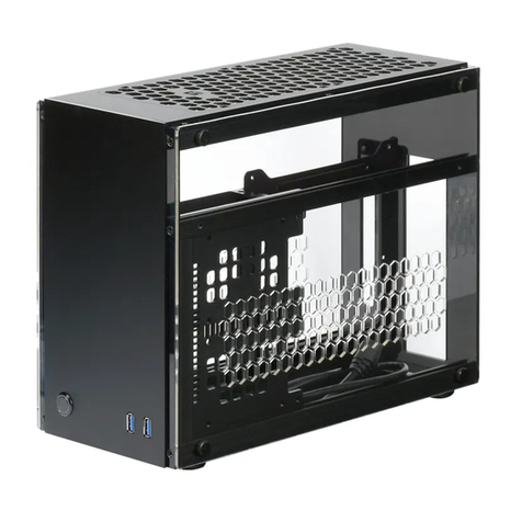
Our Project S Mini is a high-class, high-quality HTPC-case for Mini-ITX motherboards. The front
is made of high-grade aluminum, the top cover of scratch-proof tempered glass. The main fea-
ture of the case is the drawer design. The tray can be extracted for easy installaon or mainte-
nance of the system – even when the system is installed.
As with all our cases, the Project S Mini has been designed for maximum compability and va-
riability. Fully modular SSD holders allow the user to recongure the case to his own personal
needs. The Project S Mini oers ample space for a compact, air cooled system.
Another feature is the possibility to use the Project S Mini as a Mini Tower by using it standing
upright.
Accessories
Fan screws
Stand-os for mainboard
Screws for mainboard mounng
Screws for HDD mounng
Screws for 3.5” mounng frame
Mounng screws for 2.5“HDD/SSD
Mounng screws for PSU
EPS extension cable
24-Pin ATX extension cable
PCI-E 3.0 Riser Card Cable - 10 cm
If you are missing any of the items listed above, please contact our customer service
immediately: support@nanoxia-world.com
Specicaons:
Dimensions: 118,5 x 502 x 309 mm (Height x Width x Depth)
Material: Steel, aluminum, tempered glass
Internal drive bays: 1 x 3,5“ HDD
2 x 2,5“ SSD
02

Features:
Water Cooling ready
Drawer design with extractable motherboard tray for easy hardware installaon
Tempered glass top cover
2 x USB 3.0, 1 x USB 3.1 Type C
2 Slots for expansion cards
Max. VGA card length: 270 mm
Room for CPU coolers with a maximum height of up to 65 mm
Mounng hole for CPU cooler in the motherboard tray
Cable management with rubberized holes in the motherboard tray
Can be used horizontal as HTPC case or vercal as Mini Tower
RGB Rigid LED with controller behind the front cover
On the next pages you can nd some useful ps and explanaons for the opmal use of your
new case and for the installaon of your hardware.
II. Installaon Instrucons
For the installaon of your hardware, please rst pull out the drawer. For this, you need to
remove the four thumbscrews at the back of the case. You can pull the tray out parally or
completely – please keep in mind that the tray rests on wheels. For the installaon we recom-
mend that you x them.
1. Installing the Motherboard
You can mount Mini-ITX motherboards in the Project S Mini. Before installing the mother-
board, please aach the supplied stand-os rst. Aach the included EPS extension to your
mainboard.
Now place the motherboard gently inside the drawer and lead the EPS extension cable through
the opening provided in the motherboard tray. Fix the motherboard to the motherboard tray.
Aer the installaon of the power supply, you can connect the EPS extension cable to the EPS-
connector on the PSU at the underside of the motherboard-tray.
2. Installaon opons for hard drives
You can install up to three drives in the Project S Mini. One 3.5 inch drive can be mounted at
the boom in the front right corner; two addional 2.5 inch holders are available for the instal-
laon of SSDs.
03

2.1 Mounng of the 3.5 inch hard drive
The 3.5 inch drive uses decoupled mounng. For the installaon of the hard disk, please hold it
to the inner side of the chassis and use screws to x it from underneath the motherboard tray.
The hard disk is connected from the right side. Please use the cut-out in the motherboard tray
to hide the cables.
2.2 Mounng of 2.5 inch SSDs
The Project S Mini oers two dedicated 2.5 inch holders. These are xed with screws to the
boom of the case and can be removed, if not needed. The drives are secured with screws.
04

3. Removing the front panel and top cover
Please keep in mind that the top cover is made of tempered glass and as such should be
handled with care.
3.1 Removing the front panel
To remove the front panel, remove the six
screws from the inside of the drawer, which
holds it in posion (3 x above, 3 x below the
motherboard-tray). Please be aware of the
Rigid-LED connector cable, else you might
damage it.
3.2 Removing the top cover
To remove the top cover of the case, please
unscrew the four screws that hold it in place.
You can then simply take it o.
4. Fan assembly
Up to three 60 mm case fans can be mounted inside the Project S Mini.
All air intake openings of the Project S Mini are equipped with easy to clean dust lters. We
recommend that you clean them on a regular basis. This includes the air intakes for the SFX
PSU and the VGA card.
4.1 Fans on the right side panel
Three 60 mm fans can be mounted at the right
side panel. For installaon, please hold them to
the chassis from the inside and x them with
screws from the outside.
05

Case fans installed at the side of the case should exhaust air out of the case (fan rear side
facing outwards). The dust lter is magnec and can be removed and cleaned easily.
5. Installaon of the VGA card
The graphics card is installed horizontally in the Project S Mini. For the installaon, rst remove
the PCI slots by loosening the screws. Then insert the graphics card and screw it into the PCI
bracket.
For the installaon of longer VGA cards, we recommend using the rubber spacers supplied by
us to support the card in the rear area.
Connect the supplied PCI-E 3.0 Riser card cable to the PCI-E slot of your mainboard and then to
the graphics card. The high-quality cable does not need any addional power supply.
The cables are perfectly shielded and oer a parcularly stable signal transmission.
The openings in the chassis below the graphics card are equipped with a magnec dust lter.
We recommend cleaning it regularly. Simply pull the drawer out so you can reach the lter
easily.
6. Das I/O-Panel
The I/O panel includes connectors for external USB devices (2 x USB 3.0, 1 x USB 3.1 Type C),
and the microphone and headphone ports. The power-, reset-, and RGB color selector buon
are located here as well.
USB 3.0
USB 3.0
USB 3.1 type C On/O boon
RGB color selector buon
Reset buon
Audio connectors
06

7. The Nanoxia RGB Rigid LED Bar
Behind the front of your Project S Mini, a Nanoxia RGB Rigid LED Bar is pre-installed. To choose
between the dierent colors, please use the color selector buon in the I/O panel.
7.1 Connecng the Rigid LED Bar to the power supply
The Rigid LED Bar is powered by a SATA connector that can be connected directly to the power
supply.
7.2 Operaon of the Rigid LED Bar
If you want to deacvate the LED Rigid Bar, you can simply use the color selector buon in the
I/O panel as well.
07

III. Legal disclaimer:
All named products and descripons are trademarks and / or registered trademarks of the
respecve manufacturers and are accepted as protected. The design and specicaons are
subject to change without prior noce. This is part of the connuing policy of product improve-
ment at NANOXIA. Naonal product specicaons may vary. All rights reserved especially (also
in extracts) for translaon, reprinng, reproducon by copying or other technical means.
Infringements will lead to compensaon. All rights reserved, especially in case of assignaon of
patent or ulity patent.
Disposal of your old product:
Your product is designed and manufactured with high quality materials and components,
which can be recycled and reused. When this crossed-out wheeled bin symbol is aached to a
product, it means the product is covered by the European Direcve 2012 /19 /EU gild. Please
be informed about the local separate collecon system for electrical and electronic products.
Please act according to your local rules and do not dispose of your old products with your
normal household waste. The correct disposal of your old product will help prevent potenal
negave consequences to the environment and human health.
NANOXIA is a registered trademark of the PC-Cooling GmbH
PC-Cooling GmbH
Eichenallee 3
24589 Nortorf
Germany
© NANOXIA
info@nanoxia-world.com
www.nanoxia-world.com
08

IV. Support
Dear customer,
The PC case you purchased has undergone a very thorough quality control. Nevertheless,
should there be any unexpected problems with your case we ask that you rst approach the
dealer where you purchased the product. They are prepared to assist you with competent and
uncomplicated advice and praccal support.
If perhaps a few screws were missing or you might have a queson that can’t be answered by
this manual, please do not hesitate to contact us directly by e-mail.
Likewise, we would appreciate your suggesons and comments about our case very much. Our
sta will respond to all inquiries quickly and professionally.
Customers from Germany and other European countries can use the following e-mail address
for support quesons, spare parts or warranty issues:
support@nanoxia-world.com
Customers from Africa, Asia, Australia as well as North and South America can use the fol-
lowing e-mail address for support quesons, spare parts or warranty issues:
support.overseas@nanoxia-world.com
For general inquiries, comments, suggesons and the like please refer to:
info@nanoxia-world.com
We are sure that you will be sased with your Nanoxia Project S Mini for many years to come,
so please enjoy your new PC case.
Your Nanoxia Support-Team
09

© Nanoxia
Table of contents
Other Nanoxia Enclosure manuals

Nanoxia
Nanoxia DEEP SILENCE 2 User manual

Nanoxia
Nanoxia Deep Silence 5 User manual

Nanoxia
Nanoxia Deep Silence 5 Rev. B User manual

Nanoxia
Nanoxia CoolForce 2 User manual

Nanoxia
Nanoxia Deep Silence 3 User manual

Nanoxia
Nanoxia CoolForce 1 User manual

Nanoxia
Nanoxia Deep Silence 1 Revision B User manual

Nanoxia
Nanoxia Deep Silence 6 Revision B User manual

Nanoxia
Nanoxia Deep Silence 5 User manual