Nanoxia DEEP SILENCE 2 User manual


_______________________________________02
____________________________________02
______________________________________02
_________________________________________03
______________________________06
_____________________06
_____________________07
________________________08
_________________________________08
________________09
______________________10
__________________________11
__________11
_____14
_____________15
____________________________________15
_____________________16
__17
_____________________________________17
_____________________________________18
___________________________________18
______________________________________19
_________________________________________20
I. Introducon
• Specicaons
• Accessories
• Features
II. Installaon Instrucons
1. Installaon of the motherboard
2. Installaon of the power supply
3. Installaon of external drives
3.1 Opcal drives
3.2 Ulising the external 3.5 inch bay
4. Installaon of hard disk drives
5. Removing the front panel
6. Fan assembly and cleaning of the dust lters
7. Connecng the fans to the 2-channel fan controller
8. Operaon of the 2-channel fan controller
9. The I/O-Panel
10. Installaon of a water cooling
11. Connecng the front connectors with the motherboard
11.1 USB 2.0
11.2 USB 3.0
11.3 HD Audio
11.4 AC 97
III. Support
01

EN
I. Introduc on
Congratula ons on the purchase of your new Nanoxia Deep Silence 2 PC tower. We are con -
dent that you will be delighted by your new PC case for many years to come.
Nanoxia’s Deep Silence series have been designed and developed by an experienced team of
developers in Germany. The silent op mised PC cases are of the highest quality and combine
the best possible func onality with the highest level of exibility.
The Deep Silence 2 PC case o ers you plenty of space for hardware and water cooling solu-
ons. Due to the excep onal depth of the case long graphics cards can easily be accommo-
dated. Alterna vely, the spacious interior can be used to install for example a water cooling
system (240 mm radiator) between the motherboard and the hard drive cage.
Speci ca ons
Dimensions: 468 x 207 x 588 mm (Height x Width x Depth)
Material: 0.7 mm Steel
External drive bays: 2 x 5.25 inch (tool-free)
1 x 5.25 inch /w 3.5 inch adapter (tool-free)
Internal drive bays: 7 x 3.5/2.5 inch bays (decoupled)
Accessories
Rubber sealings for
tube holes
EPS 4+4-Pin extension Fan screws Stand-offs
for mainboard
Screws for
mainboard mounting
Screws for HDD
mounting
Screws for 3,5” moun-
ting frame
Mounting screws for
2.5“HDD/SSD
Mounting screws
for PSU
Thumbscrews
If you are missing any of the items listed above, please contact our customer service immediately:
support.eu@nanoxia-world.com (Germany and Europe); support.overseas@nanoxia-world.com (interna-
onal)
02

Noise Insula on
The Nanoxia Deep Silence 2 has been developed with the aim of o er the buyer a low-noise
case, while at the same me allow for extremely low system temperatures. The sound insula -
on design of the Deep Silence 2 is based on mul ple interac ng design elements:
The most important part is the large scale lining of the case with sound-absorbing insula on
materials. These materials are manufactured speci cally to meet the requirements of the
developers of the Nanoxia Deep Silence case series. The thickness of the material was carefully
selected a er extensive tes ng to ensure the op mum balance between noise suppression
while maintaining acceptable temperatures.
Included are special rubber seals which can be used to alterna vely close the tube holes next
to the PCI slot covers and above the rear chassis fan, in case you should not need them.
The removable Nanoxia VentCovers mask the 120/140 mm fan holes in the case top and the
side panel. They allow it to choose between the least possible noise and improved case ven la-
on. The covers under the top cover are equipped with sound-absorbing foam. The VentCover
in the side panel can be equipped with a self-adhesive bitumen mat. Such a bitumen mat is
included separately to ensure the best compa bility to high CPU coolers.
Features:
Complete customisable soundproo ng with high quality materials mee ng industrial
standards
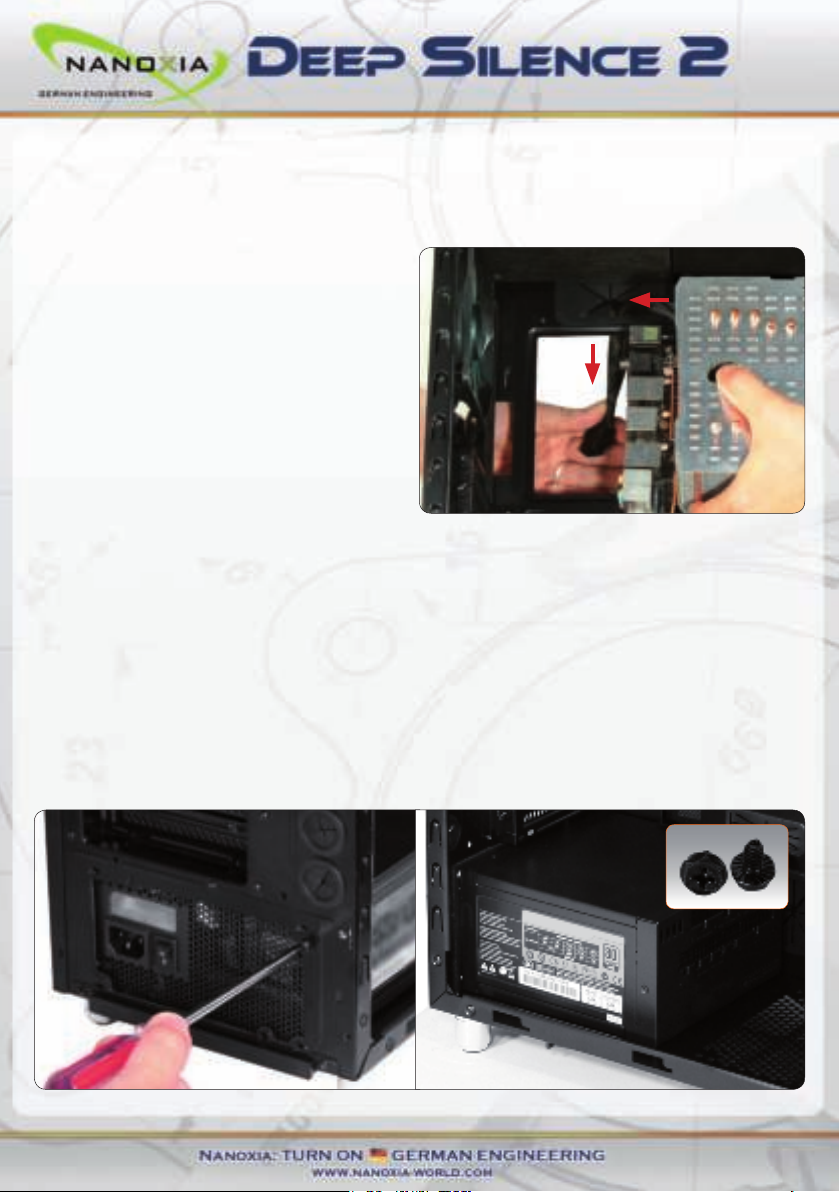
Tool-free moun ng of op cal drives
Moun ng bracket for a 120/240 mm water cooling radiator or up to two 120 mm
fans behind the HDD cage
Max. VGA length 345 mm (up to 370 mm without the Moun ng Bracket)
Room for CPU coolers with a maximum height of up to 165 mm
Moun ng hole for CPU cooler in the motherboard tray
Cable management with nine rubberized holes in motherboard tray
Nanoxia VentCover (sound proofed) : 2 x top cover, 1 x side panel (le )
2 x USB 3.0, 1 x USB 2.0
2-channel fan control for up to six fans
03

EN
Another design element for opmum sound insulaon is a sound-insulated front door. The
door is equipped with sound-absorbing foam and perfectly suited to minimize noise from the
opcal drives. The lower part of the case front is also insulated with bitumen to absorb the
noise from the hard disks and the front mounted fans.
The hard disk drives are installed on trays which feature rubber grommets that are designed to
absorb any vibraons caused by the HDDs.
The power supply is isolated from the case by a exible rubber framework and also rests on
rubber contact points on the boom of the PSU. This reduces any vibraons caused by the PSU
being transmied onto the case.
The whole concept of sound proong of the Deep Silence 2 meets the highest expectaons.
Venlaon System
The Nanoxia Deep Silence 2 has an integrated venlaon system consisng of three standard
Deep Silence fans and a built-in 2-channel fan controller for up to six fans. A total of up to nine
fans can be mounted.
To assist the venlaon of the system and in parcular of the hard disk drives, a special Moun-
ng Bracket for two 120mm fans is located internally on the HDD cage. This bracket is perfect
to be ed with a 120 mm or 240 mm radiator or two 120 mm fans.
The Deep Silence 2 axial ow fans have been specically opmized for very quiet operaon.
Both the fan frame and impeller were developed and opmized in extensive trials in a wind
tunnel. In addion to be remarkably low noise, the Nanoxia fans also provide an excellent com-
binaon of rotaon speed and air ow. The high-quality rie bearing guarantees a parcularly
long service life of up to 80,000 hours.
The range of fan speeds and controls was designed to enable the user to adjust the case ven-
laon to his own needs.
Front and boom are equipped with easy to clean dust lters.
04

Watercooling-ready
The Nanoxia Deep Silence 2 can be con gured for use of water cooling systems. The moun-
ng bracket between motherboard and hard drive cage is designed to make op mal use of
the above-average depth of the Nanoxia Deep Silence 2 case for water cooling systems. The
bracket can be used to install a 120/240 mm radiator. If necessary, the radiator can then even
be equipped with fans on both sides. Due to the generous propor ons of the case, spacing
problems are of no concern.
If you want to mount a compact water cooling system on the moun ng bracket, you should
check before the installa on whether the factory hoses between cooler and radiator are of
su cient length.
Rubber hose guides:
The Deep Silence 2 o ers four rubber hose guides, so that the appropriate water cooling com-
ponents can be operated or mounted externally.
On the next pages you can nd some useful ps and explana ons for the op mal use of your
new case and for the installa on of your hardware.
Standard Equipment:
Front: 2 x 120 mm Nanoxia DS-fans (max. 1,300 RPM)
Rear: 1 x 120 mm Nanoxia DS-fan (max. 1,300 RPM)
Op onal Equipment:
Front: 2 x 120 mm fan (Moun ng Bracket on the HDD-cage)
Side: 1 x 140/120 mm fan
Bo om: 1 x 120/140 mm fan
Top: 2 x 120/140 mm fans
05

Installaon Instrucons
1. Installing the Motherboard
In order to ensure an easy installaon of your motherboard, we suggest the following
procedure:
1. Please consult the following charts to nd your motherboard form factor:
E-ATX Mainboard ATX Mainboard Micro-ATX Mainboard Mini-ITX Mainboard
2. Aach the spacers according to your
motherboard form factor.
3. Aach the included EPS extension cable
on to your motherboard – do not connect it
to the power supply yet.
EN
06

4. Next you should mount the CPU cooler - for very large CPU coolers, the aachment of the
EPS extension cable aer installaon can be dicult.
5. Now place the motherboard gently inside
the case and lead the EPS extension cable
through the opening provided in the top le
of the mainboard tray.
6. Fix the motherboard to the motherboard tray
7. Aer the installaon of the power supply, you can connect the EPS extension cable to the
EPS-connector on the PSU at the back of the motherboard-tray.
2. Installaon of the power supply
Please install the power supply according to the diagram below and secure it with the included
PSU screws.
07

3. Installaon of external drives
3.1 Opcal drives
To install the opcal drives, please remove both side panels. The installaon of opcal drives is
tool-free.
Then loosen the lock on both sides by drag-
ging the black slider backwards (1).
Then slide the drive into the desired posi-
on.
Lock the holder by pushing the slider back
to its original posion (2).
Remove the 5.25 inch cover by pulling the
lateral lng lever cauously towards you
and take out the cover.
Then slide the drive into the desired posion. Lock the holder by pushing the slider back to its
original posion.
Please note that the two lower shas are equipped with steel panels, which you have to
remove when you want to use the lower drive bays. To do this, move the steel panels gently
back and forth unl you can remove them.
EN
08

Before you take out the internal adapter,
please remove the 3.5 inch steel cover as
shown on the picture.
Open the two quick release locks of the 5.25 inch bay and remove the mounng frame. Then
aach the card reader in the frame, as shown below.
Then place the frame with the card reader back into the slot and lock the quick release.
Finally, aach the included 3.5 inch adapter to the front cover over the card reader.
3.2 Ulizing the external 3.5 inch bay
If you for example desire to place a 3.5 inch card reader, you can use the internal adapter for
this purpose.
09

EN
4. Installaon of hard drives
Install the 2.5 or 3.5 inch hard drives in the illustrated mounng frames. In order to extract the
frame, squeeze the protruding brackets and pull the slide out gently.
To install a hard drive into a bracket insert the disk so that the connectors point to the back and
aach the hard drive using the screws provided.
For the ng of 3.5 inch hard drives please use the holes in Figure 4A (marked red).
For the ng of 2.5 inch hard drives please use the holes in Figure 4B (marked red).
The hard drives slides oer a second pair of mounng holes, so it is possible to shi the posi-
on of the drives. Those are marked in blue on the picture.
To lock the drive, push the bracket with the
drive back installed back into the slot unl
the bracket is re-engaged.
gure 4A gure 4B
10

5. Removing the front panel
To remove the front panel, simply hold the
cutout at the boom of the front panel and
pull it towards you with a rm tug.
If you remove the front, please note the
I / O panel cables at the top of the front.
Please be cauous here.
6. Fan assembly and cleaning of the dust lters
The air intake openings in the front and at the boom of the Deep Silence 2 are equipped with
easy to clean dust lters. We recommend that you clean them on a regular basis.
To clean the dust lter is usually sucient to vacuum these carefully with a vacuum cleaner
(low level).
To switch the fans in the front or to clean the dust lters, please remove the front panel rst.
Next, remove the four screws with which the dust lter is connected to the front and take it
out.
Please be advised that the fans are screwed to the dust lter.
The front dust lter allows the installaon of either 2 x 120 mm or 1 x 140 mm fans. Two
120mm Deep Silence fans ( approx. 1,300 rpm) are preinstalled.
11

EN
Op onal case fans:
Note: Addi onal case fans in the side panel and the bo om of the Deep Silence 2 should be
mounted so that cooler air is introduced into the case. If you install case fans in the moun ng
bracket, those should support the movement of air from front to back.
Case fans installed at the top of the case should exhaust air out of the case.
We recommend the use of the 120 or 140 mm Nanoxia Deep Silence fans, available separately.
These are technically and visually equivalent to the factory-installed case fans and will work in
perfect harmony with the built-in fan control of your case.
Addi onal fans in the moun ng bracket behind the HDD cage:
If you want to mount addi onal fans inside the case, for example to op mize disk ven la on,
you can use the specially developed moun ng bracket that is screwed to the hard drive cage.
Please rst remove the screws, as shown on picture 6C.
On the back of the disk cage the frame is
only hooked - here it is su cient to loosen
the screws slightly (picture 6D).
Hold the fan from the inside to the bracket
and screw it in from the outside. Then hook
the moun ng bracket with the fans back in
the cage and a ach it with the three screws.
picture 6C picture 6D
12

13
Addional fans in the top cover:
If you want to install more fans at the top of
the case, please remove the Nanoxia Vent-
Cover rst by unscrewing the screws on the
outside of the case.
Then hold the fan from the inside and secu-
re it to the top by fastening the screws from
the outside.
Addional fan in the side panel:
If you want to accommodate a fan in the
side panel, please remove the Nanoxia Vent-
Cover rst by unscrewing the screws on the
outside of the case.
Please place the fan on the inside of the side
panel and screw it in from the outside.
Addional fan at the case boom:
If you want to install a 120 or 140 mm fan
on the boom of the case, please note that
you need to remove the dust lter.
Pull it out just as far as you can easily reach
the screw holes.

EN
14
The dust lter at the boom:
The dust lter at the boom can be pulled
out for easy cleaning.
7. Connecng the fans to the 2-channel fan controller
The fan controller is powered by a 4-pin Molex connector that is connected directly to the
power supply.
The controller has two channels (A and B), with each channel able to control up to three 3-pin
fans, therefore a total of six fans can be controlled.
The fan controller is not designed for the operaon of powerful fans. Please take this into
account in parcular when using fans from other manufacturers.
The maximum power per channel must not exceed 18 was.

15
8. Operaon of the 2-channel fan controller
The sliders of the fan control can be found behind the upper front door. The le slider operates
the fans of the rst channel (A1, A2 and A3); the right slider controls the fans of the second
channel (B1, B2 and B3).
9. The I/O-Panel
The I/O panel includes connectors for external USB devices (2 x USB 3.0, 1 x USB 2.0), and the
microphone and headphone ports.
The blue USB connectors are high-Speed USB 3.0; the USB 2.0 port is black. The le audio con-
nector (when viewed from the front) is for headphones, the right is intended for a microphone.

EN
10. Installa on of a water cooling
The Nanoxia Deep Silence 2 is equipped with a special moun ng bracket that is ideally pre-
pared to receive a 120/240 mm radiator. It makes it possible to mount a radiator and can be
equipped with up to four fans for maximum heat-dissipa on. Including the pre-assembled 2
x 120 mm Nanoxia Deep Silence fans behind the front panel, up to 6 fans provide a superior
cooling performance.
In order to x a radiator on the Moun ng Bracket, you need to remove the moun ng bracket
as described in Chapter 6 (Fan assembly and cleaning the dust lters).
Next, set the radiator you to install at on the table. Posi on the moun ng bracket with the
outside on the radiator as seen in the picture below.
Put one or two 120 mm fans into the Moun ng Bracket and connect fans, bracket and radiator
with extra-long screws.
For maximum cooling capacity of your radiator, you can then mount up to two addi onal 120
mm fans on top of the radiator.
Radia-
tor with
2 fans
mounted
Radia-
tor with
4 fans
mounted
16

11. Connecng the front connectors with the motherboard
11.1 USB 2.0
Diagram 11 A shows the standard pin assignment of the USB cable plug. The pins are assigned
in a way to t on current motherboards as shown in diagram 11B.
Please refer to the motherboard and check that the internal USB port of your motherboard is
idencal to the one shown in diagram 11A.
If the pin allocaon of the internal USB port is the one shown in diagram 11A it is then possible
to connect the cable.
If, however, the pin allocaon of the internal USB port and the one shown in diagram 13A
dier, please consult a professional.
Wrong connected cables might cause serious damage to your hardware.
Pin assignment of the front panel USB cable plug.
Typical pin assignment of an internal USB port on a current market motherboard
Connecng USB cables plug with internal USB port of the motherboard
diagram 11A
diagram 11B
diagram 11C
17

EN
11.2 USB 3.0
Diagram 11D shows the typical pin assignment of the internal 19-Pin USB 3.0. The pins are
assigned in a way to t on a current motherboards (diagram 11E). Referring to the mother-
board manual, please check that the internal 19-pin USB 3.0 port is idencal to the one shown
in diagram 11E.
If the pin allocaon of the internal 19-Pin USB 3.0 plug and the one shown in diagram 11E are
the same, please connect the cable. If, however, the pin allocaon of the internal 19-Pin USB
3.0 plug and the one shown in diagram 11E dier, please consult a professional. Wrong con-
nected cables might cause serious damage to your hardware.
If your motherboard does not have internal USB 3.0 port, you can acquire an internal 19-pin to
external 2x USB 3.0 Type A adapter cable.
11.3 HD Audio
Diagram 11F shows the pin assignment of the standard HD audio cable plug. The pins are assi-
gned in a way to t on a current motherboards. Referring to the motherboard manual, please
check that the HD audio port is idencal to the one shown in diagram 11F.
If the pin allocaon of the HD audio plug and the one shown in diagram 11F are the same, ple-
ase connect the cable. If, however, the pin allocaon of the HD audio plug and the one shown
in diagram 11F dier, please consult a professional. Wrong connected cables might cause
serious damage to your hardware.
Pin allocaon of the internal HD Audio cable plug
diagram 11D diagram 11E
diagram 11F
18

11.4 AC 97
Diagram 11G shows the standard pin assignment of the AC 97 cable plug. The pins are assig-
ned in a way to t on a current motherboards as shown in diagram 11H.
Referring to your motherboard manual, please check if that the AC 97 port is idencal to the
typical shown in diagram 11H.
If the pin allocaon of the AC 97 plug and the one shown in diagram 11H are the same, please
connect the cable.
If, however, the pin allocaon of the AC 97 plug and the one shown in diagram 11H dier,
please consult a professional. Wrong connected cables might cause serious damage to your
hardware.
Pin assignment of the front panel AC 97 cable plug
Typical pin assignment of an AC 97 port on a current market motherboard
diagram 11G
diagram 11H
19
Table of contents
Other Nanoxia Enclosure manuals

Nanoxia
Nanoxia Deep Silence 5 User manual

Nanoxia
Nanoxia Deep Silence 5 Rev. B User manual

Nanoxia
Nanoxia Deep Silence 5 User manual

Nanoxia
Nanoxia CoolForce 1 User manual

Nanoxia
Nanoxia Deep Silence 3 User manual

Nanoxia
Nanoxia PROJECT S MINI User manual

Nanoxia
Nanoxia Deep Silence 1 Revision B User manual

Nanoxia
Nanoxia CoolForce 2 User manual

Nanoxia
Nanoxia Deep Silence 6 Revision B User manual