NAPCO iSeeVideo ISEE-SCHGW User manual

1
NAPCO iSeeVideo
ISEE-SCHGW
Installation Guide
WI1795 04/09
333 Bayview Avenue
Amityville, New York 11701
For Sales and Repairs, (800) 645-9445
For Technical Service, (800) 645-9440
Publicly traded on NASDAQ Symbol: NSSC
© NAPCO 2009
Designed exclusively for use with NAPCO iSeeVideo VideoAlert.net Server
COMPATIBLE
R
ISEE-SCHGW
Single Channel Video Gateway
Internet
VideoAlert.net
SERVER

2
Table of Contents
Features and Specifications ..............................2
System Overview ...............................................3
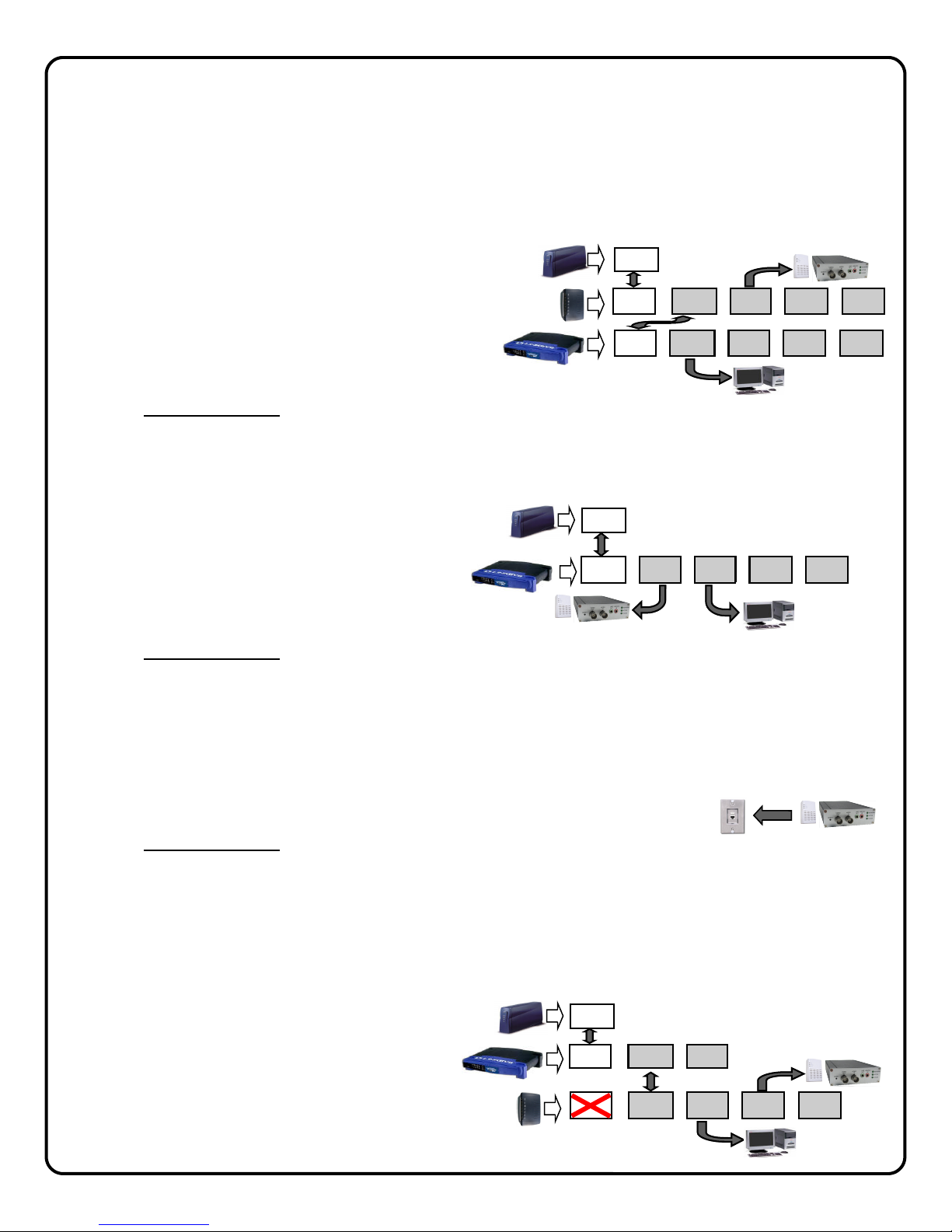
Installation Overview ..........................................4
Installing the ISEE-SCHGW ..............................5
Connecting to the Internet..................................6
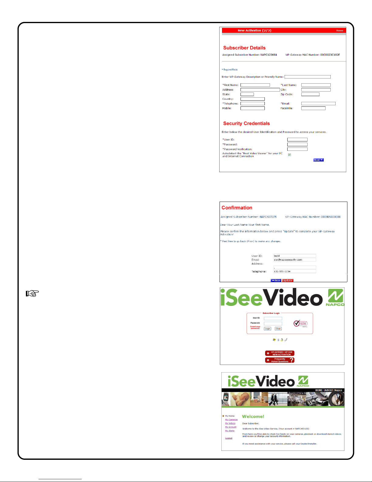
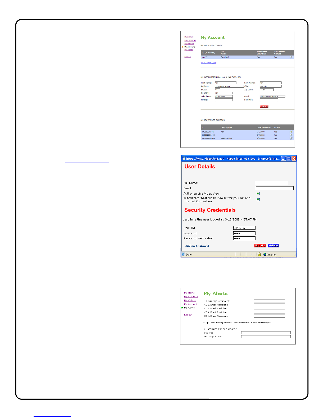
Account Activation..............................................7
Adding Gateways to an Existing Account ........10
Configuring Motion Detection...........................12
Setting a Motion Schedule ...............................13
Viewing Stored Video.......................................14
Setting up the EOP modules............................15
Creating a Secure EOP Network .....................16
Frequently Asked Questions............................17
Troubleshooting ...............................................18
NAPCO Limited Warranty ................................20
NAPCO Security Systems, Inc.
333 Bayview Avenue, Amityville, New York 11701
For Sales and Repair, call toll free: (800) 645-9445
For direct line to Technical Service,
call toll free: (800) 645-9440
Internet: http://www.napcosecurity.com
Windows®, and the Windows logo are registered trademarks of Microsoft Corporation
Apple®and the Apple logo are registered trademarks of Apple Computer, Inc.
Linux®is a trademark of Linus Torvalds. The Linux penguin logo was created by Larry Ewing.
Dimensions 1.2 x 3.55 x 5.5
(H x W x D), Inches
Input Voltage: 12VDC via 100-240VAC to
12VDC Transformer (supplied)
Current: 1,000mA
(Transformer rating)
ISEE-SCHGW SPECIFICATIONS
ORDERING INFORMATION
SCHGW -EOPKT/12 One Gateway Kit
Includes:
(1) ISEE-SCHGW , Power Adapter.
(2) ISEE-EOP MOD200, 6' CAT5 cable.
(12) months VideoAlert.net service.
SCHGW -EOP/12 Additional Gateway Kit
Includes:
(1) ISEE-SCHGW , Power Adapter.
(1) ISEE-EOP MOD200, 6' CAT5 cable.
(12) months VideoAlert.net service.
ISEE-SCHGW/12 Single Channel Gateway
Includes:
(1) ISEE-SCHGW , Power Adapter.
(12) months VideoAlert.net service.
G-BOX Internet Interface Module
Includes:
(1) G-BOX
(1) Power Adapter.
(1) 3’ CAT5 Patch Cable
G-BOX SPECIFICATIONS
Dimensions 5 5/8 x 3 3/8 x 1 1/8
(H x W x D), Inches
Input Voltage: 9VAC via 120VAC to 9VAC
Transformer (supplied)
Current: 180mA Max (all 4 LAN ports in
use)
ISEE-EOP-MOD200
SPECIFICATIONS
Dimensions 5.5 x 4.0 x 2
(H x W x D), Inches
Input Voltage: 100-240V AC, 50-60 Hz
ISEE-SCHGW Specifications
• 1 Video Input, NTSC/ PAL auto detect
• 1 Video Output
• Video Compression: MPEG-4/ M-JPEG Dual Stream simultane-
ously
• Resolution: 4CIF, CIF, QCIF
• Max: 704 x 480 (NTSC) / 704 x 576 (PAL)
• Default: 352 x 240 (NTSC) / 352 x 288 (PAL)
• Min: 176 x 120 (NTSC) / 176 x144 (PAL)
• Frame Rate: Up to 30 frame per second in all resolution
• Audio Compression G.726 ADPCM, G.711 PCM
• Video Trigger Input
• Motion Detection: 4 Detection Areas with individual sensitivity
controls
• LAN: DM9102D, 10/100BaseT, Auto-MIDX
• LED Indicators: Ready, Active, Network
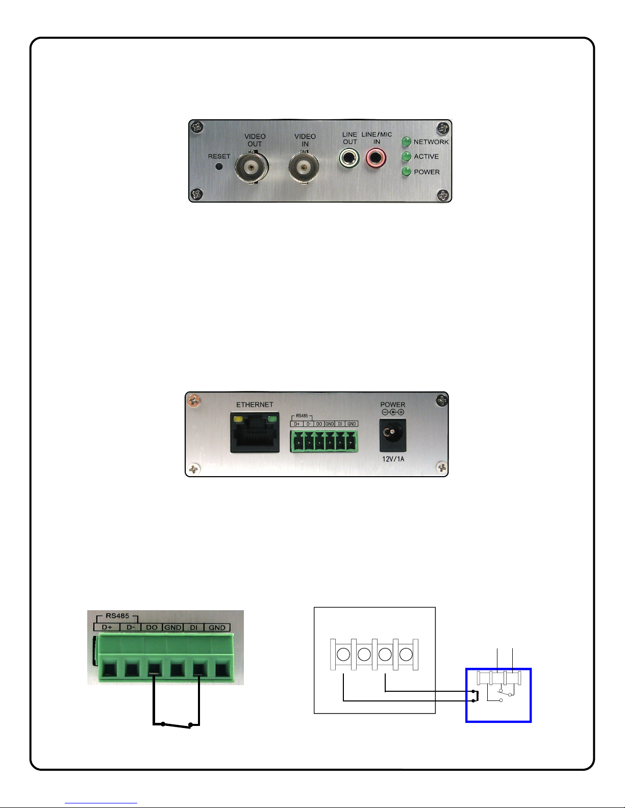
• Connectors:
• Ethernet RJ-45, Power, Reset, Composite Video In, Com-
posite Video out, Audio In, Audio Out
• External Power Adapter: 12V/1A, 100~240 VAC, Switching
• Certification: CE/ FCC
• Dimensions: 90mm (W) x 30mm (H) x 140mm (L)
• Operation Environment
• Temperature: 0-40 ºC
• Humidity: 20-80% RH

3
Overview of the iSeeVideo VideoAlert.net System
Internet
Internet
G-BOX
(OPTIONAL)
VideoAlert.net
Server
Customer's
Broadband
Modem
ISEE-EOP-MOD200
The NAPCO iSeeVideo VideoAlert.net system allows remote video
internet monitoring of residential and light commercial properties. Its
unique subscription-based account system provides the opportunity to
realize recurring revenue from typical CCTV video installations.
The iSeeVideo ISEE-SCHGW is a Single Channel Video Gateway that
converts any analog CCTV camera into internet ready IP camera. Using
MPEG4 compression, it provides video images with a maximum of 704 x
480 lines of resolution that can be viewed through the iSeeVideo
VideoAlert server on virtually any computer in the world at up to 30 frames
per second. The Gateway provides an input trigger that when activated,
will prompt the transmission of video clips to the VideoAlert.net server. It
also has a local video output that provides a local video signal for
connection to a monitor or for local distribution using a video modulator.
The Gateway provides (at no additional service charge) dynamic IP
support through the NAPCO iSeeVideo DNS server - every 16 seconds
the Gateway checks in with its DNS server to insure that the DHCP IP
address is always kept current.
The ISEE-EOP-MOD200 is an optional Ethernet-Over-Power module that
allows the transmission of video signals over the existing power lines of a
home or business. The simple Plug-n-Play installation allows the
iSeeVideo devices to connect to the G-BOX or Customer’s router by
simply connecting the devices to their respective EOP modules and then
into the electrical outlets. The modules create a powerline network ideal
for the transmission of video signals at up to 200 megabits per second.
The EOP modules are fully capable of transmitting data across the phases
of typical residential multiphase power systems.
The G-BOX (Patented) is an optional Internet Video accessory that allows
optimum performance on cable broadband service installations by
establishing a point to point connection between the video gateway and
the PC. The G-BOX is designed to be placed between the broadband
modem and router, and also functions as a router for cases where the
customer's PC is the only device connected to the broadband modem.
The G-BOX will also function as a switch if devices are plugged into the
LAN ports. provides 4 auto-sensing LAN ports for connection to the ISEE-
SCHGW and to the customer's PC, router or other equipment. The G-
BOX functions as both a DHCP client and server, to fit seamlessly into
all typical DHCP environments. The G-BOX also functions as a switch
in cases where additional port expansion is required.
The NAPCO VideoAlert.net server maintains VideoAlert accounts and
allows subscribers to view their ISEE-SCHGW gateway from any personal
computer or web enabled cell phone. It is compatible with computers
running the Microsoft Windows®, Apple®and Linux®operating systems
and is also compatible with any WAP enabled cell phone or mobile video
device. The server also automatically notifies the subscriber by email
upon receipt of triggered video events and archives them for viewing at a
later time. Each subscriber account provides 50Mb of storage, allowing
the archiving of about (75) 10 second video clips (adjustable 5 sec pre-
alarm and 5 sec post-alarm). The server is designed to allow the customer
to have complete control of their account in regard to passwords, email
addresses and other personal information.

4
INSTALLING, ACTIVATING AND CONFIGURING THE ISEE-SCHGW
The installation and activation of the VideoAlert system has been designed to be "plug and play", requiring no special
training or tools and no knowledge of TCP/IP or networking for typical installations. The primary installation steps de-
picted below are covered in detail on the following pages:
1Install the ISEE-SCHGW gateways and cameras, (page 5)
2Wire The Network Connection. (page 6)
3Activate the new ISEE-SCHGW account on the VideoAlert server. (page 7)
4Configure the gateway for motion detection triggering (Optional) (Page 12).
(Optional) The gateway may be configured for motion detection on-line by simply going to www.VideoAlert.net,
and entering the gateway security code number printed on the sticker on the bottom of the gateway.
BROADBAND
MODEM
CUSTOMERS ROUTER
(OPTIONAL)
Alternate G-BOX
configuration to be
used for optimum
performance in
cable broadband
installations
CUSTOMER'S PC
FROM BROADBAND
PROVIDER
OVERVIEW OF TYPICAL ISEE-SCHGW INSTALLATION
(Power connections not shown)
ISEE-SCHGW
ISEE-SCHGW

5
1INSTALL AND WIRE THE ISEE-SCHGW
Descriptions of Terminals and Connections and Indicators
VIDEO IN
Connect BNC connector from the analog camera to the Video IN connector.
VIDEO OUT (Optional)
To provide a video signal to local monitor or video distribution system, connect to video out terminal.
Audio LINE / MIC IN (Optional)
Connect a standard PC compatible microphone to the 3.5mm LINE/MIC Input for 2 way audio operation.
Audio LINE OUT (Optional)
Connect a powered speaker to the 3.5mm LINE OUT jack for 2 way audio operation.
NETWORK LED
Flashes to indicate an active network connection.
ACTIVE LED
Flashes to indicate that video device is being accessed (viewed).
POWER
Lights to indicate that module power is present.
ETHERNET
Connect CAT5 cable from broadband modem or network to RJ-45 terminal.
POWER
Connect to supplied 12VDC power adapter.
TRIGGER INPUT TERMINALS
To initiate transmission of video to the VideoAlert.net server, wire a normally closed relay across the DO and DI terminals.
A momentary open across this connection will trigger video. The trigger input feature must be activated in Advanced Fea-
tures (page 14).
RED
CONTROL
PANEL
AUX
PWR
12V
(-)
(-) (-)
(+)
PGM BLACK
N/O N/C
RB1000
COM
Typical connection to control panel PGM Output
using NAPCO RB1000 form “C” relay
DO DI
Note: Prior to using the audio
feature, it is recommended that
the viewer/listener obtain any
required advance consent of the
occupants of the premises.

6
2WIRE THE NETWORK CONNECTION
Cable Modem Service Installation
The use of the optional G-BOX in Cable Broadband service applications is highly recommended to provide optimum
frame rate and resolution performance. Follow the installation and connection steps below:
NOTE: If no G-BOX is available, the Cable installation may be wired in same configuration as DSL Modem, below.
1 Power down Cable Modem and Router.
2 Wire G-BOX in standard configuration as shown
(G-BOX WAN to Modem WAN).
3 Wait 15 minutes and power up Cable Modem.
4 Wait 1 minute and power up G-BOX, then Cus-
tomer’s Router.
5 Test local PC for Internet connectivity (open internet
browser and browse internet).
6 Go to www.VideoAlert.net and click NEW ACTIVATION to activate account.
Some ISP providers lock onto the MAC address of the first device after the modem. Powering down the
modem for 15 minutes will force the ISP to recognize the new MAC address of the G-BOX upon power up.
DSL Broadband Modem Installation
1 Power down DSL Modem and Router.
2 Wire as shown.
3 Wait 15 minutes and power up Modem.
4 Wait 1 minute and power up VIP Devices and
then Customer’s Router.
5 Go to www.VideoAlert.net and click NEW ACTIVATION to activate account.
ISP Type cannot be identified
In some commercial applications, it may not be possible to identify the type of ISP, or identify the modem or routers that may
be in front of the internet connection provided by the subscriber. In these cases, wire as shown below:
1 Connect the VIP devices directly into the network connection as shown (typically an network RJ45 jack connected to a
router). This corresponding port on the router must provide access to the internet.
2 Power up the VIP Device.
3 Go to www.VideoAlert.net and click NEW ACTIVATION to activate account.
This configuration will work for most commercial installations. If there is no Internet connectivity, there may be an enter-
prise class router and firewall between the network jack and the outside internet connection. This connection can be
completed by asking the IT professional to open this port to the outside world.
NOTE: If additional ports are required, the G-BOX may be used as a switch
1 Power down all devices to be connected to the G-BOX.
2 Connect the devices to the G-BOX LAN ports as
shown.
3 Power up all devices, wait one minute, power
down and then up again to ensure proper switch
operation.
BROADBAND
DSL
MODEM
WAN
(INTERNET)
CUSTOMER'S
ROUTER CUSTOMER'S PC
AND OTHER DEVICES
WAN LAN1 LAN2 LAN3 LAN4
VIP Devices
NETWORK
CONNECTION
VIP Devices
CUSTOMER'S
BROADBAND
DSL
MODEM
G-BOX
WAN
(INTERNET)
WAN LAN1 LAN2 LAN3 LAN4
VIP Devices
WAN LAN1 LAN2 LAN3 LAN4
CUSTOMER’S PC AND
OTHER DEVICES
G-BOX
WAN LAN1 LAN2 LAN3 LAN4
VIP Devices
CUSTOMER’S PC
AND OTHER DEVICES
WAN LAN1 LAN2
BROADBAND
MODEM
WAN
(INTERNET)
CUSTOMER'S
ROUTER

7
NEW ACTIVATION
1. To activate your new Video account, simply type the fol-
lowing Internet address in your Web browser:
https://www.videoalert.net/
...and the following webpage appears:
Click the NEW ACTIVATION button.
The New Activation screen will appear. Enter the 8
character Security Code printed on the label on the
bottom of the gateway.
S C _ _ _ _ _ _
Click Next
2. The Dealer Branding screen will appear. Enter your
Company Dealer Admin ID and Password and click
Next
When Dealer Branding is successful, a screen offering the
following options will appear:
Create Subscriber Account Now
Click to create a new Subscriber account with this gateway
and enter the Subscriber details (see below).
ADD or REPLACE a VIP Device
To add or replace a gateway to the account click here. See
Adding additional gateways to an existing account for more
details.
Brand Another VIP Device
If there are multiple gateways to be installed, click here to
brand these devices.
Go to Login Page
Click here to go directly into your gateway log-in
screen.
For a single gateway system, click CREATE Subscriber Account
3ACTIVATE THE VideoAlert.net ACCOUNT
Once the ISEE-SCHGW and G-BOX have been completely wired and powered up, the VideoAlert.net
account is ready to be activated. These activation steps, include the branding of the gateway to your
Company's personalized VideoAlert.net web page, registration of the gateway and the adding of Users
to the account.
ISEE-SCHGW
Security Code S C _ _ _ _ _ _

8
3. Create Subscriber Account Now
Click to bring up the Subscriber Details screen, where
the basic account information is entered.
Enter your name, address, telephone number and other
information in the appropriate fields as shown in the im-
age at right.
The User ID and Password entered at this step will be-
come the Master User of the account and will be the
only User to have administrative privileges (the ability to
program Advanced Settings and add Users to the ac-
count).
NOTE: All field descriptions marked with an asterisk (*)
must be completed.
! IMPORTANT - Change your Password
Click Next
4. Confirmation
The "Confirmation" section verifies all information en-
tered above.
Be sure to check the accuracy of the information dis-
played, and if changes are required, click the Prev but-
ton to edit any previously entered information.
When you are sure the information displayed is correct,
click the Update button to complete your new account
activation procedure.
If you forgot your password, click the "Forgot Your
Password?" link on the Subscriber Login screen and
an email with your password will be sent to the email
address listed.
5. Login Screen
The iSeeVideo login screen will appear. Test the ac-
count by logging in with the new User ID and Password.
6. Welcome screen
If login is successful, the Welcome screen will appear.
This is the User's "Home" screen, and will allow them to
manage their account, view gateways and stored video.

9
7. My Account
Click My Account to view account information. From
this screen, you can update your account informa-
tion (My Information), and add Users to the account.
To add a new User to the account, click
Add a New User.
8. Adding additional Users. To add User to the ac-
count, click Add a New User and the User Details
screen opens, allowing you to add new users in the
fields shown. Note: All fields are required.
Enable (check) Authorize Live Video Review if to
allow the user to view live video sat any time.
By default, Auto-detect "Best Video Viewer..."
should always be enabled.
Click Update to add the new user and return to the
previous screen, or click Prev to cancel and return
to the previous screen.
The system supports a maximum of 5 Users, includ-
ing the Primary User.
9. Click Email Alert Settings to enter the Email ad-
dress of those Users you wish to be notified via
email when a triggered motion detection event oc-
curs. The email message will include a link to the
account and will allow them to review stored video.
The system supports a maximum of 5 Users, includ-
ing the Primary User.
You may also enter the subject you would like the
User to see on the subject line of the email, as well
as text in the message body.
To activate the video motion detection feature, see
page 13.

10
1. Return to the www.videoalert.net login screen
and click the NEW ACTIVATION button.
The New Activation screen will appear. Enter the
8 character Security Code printed on the label on
the back of the gateway to be added.
S C _ _ _ _ _ _
Click Next
2. The Dealer Branding screen will appear. Enter
your Company Dealer Admin ID and Password
and click Next
3. After Dealer Branding is complete, click Add or
Replace a VIP Device.
Adding or Replacing a gateway on an existing account.
Once the gateway has been registered and the account has been created, additional gateways, if any may
be added to the account through the following steps:

11
4. The next screen that appear will allow the regis-
tration of the gateway to the correct account. A
pull-down menu will appear, listing all accounts
assigned to the Dealer ID entered in the branding
screen.
Select the correct account from the list by clicking
it and then click Next to continue.
5. The following screen allows the entry of the
gateway description in the Enter New Device
Description field.
Click the pull-down menu and select Add De-
vice to complete the addition of the new gate-
way to the account.
NOTE: If replacing a VIP Device assigned to
the account, select from the pull-down menu the
device you wish to replace.
Click Next to continue.
6. When the activation is complete, the log in screen
will appear, with the message "VIP Activation
completed successfully!"

12
CONFIGURATION
1. To configure the new ISEE-SCHGW , simply
enter the following Internet address in the
Web browser:
http://www.VideoAlert.net
...and the following webpage appears:
Log in to your account, type your
Username and Password.
4Configuring the ISEE-SCHGW for Motion Detection (Optional)
Once the ISEE-SCHGW and G-BOX have been completely wired and powered up, and the account has
been activated, the ISEE-SCHGW may be configured. The next several pages will guide you through
the on-line configuration process.
Note: If the ISEE-SCHGW is only to be used for live viewing and there are no plans to trigger video mo-
tion events to the VideoAlert.net server, configuration is not required.
Video On Demand Button
To initiate the recording of a video
clip while the ISEE-SCHGW cam-
era is being viewed, simply click
the Video On Demand button. A
10-second video clip will be re-
corded and stored in My Videos.
2. Click on My Cameras and a Live image from the ISEE-SCHGW appears.

13
ADVANCED FEATURES (OPTIONAL)
The ISEE-SCHGW supports pixel-based motion
detection that allows the gateway to send motion
triggered video clips to the VideoAlert.net video
server upon motion in a selected area.
To configure the gateway for mo-
tion detection, enter Video Motion
Settings mode my clicking the
Video Motion icon. The Video
Motion Settings screen will appear.
Click the Active box to enable pixel-based motion
detection. To set a motion detection window, click
the colored box on the right and drag the window
into the live image.
Simply drag the window to a specific section of the live view screen and size it appropriately by pressing
SHIFT and dragging a side of the window. Once the window is properly positioned and sized, the sensitiv-
ity threshold can be set by dragging the corresponding threshold slider to the left for less sensitivity and to
the right for more.
The gateway has the ability to store video recorded before the actual sensing of motion. Use the PRE
and POST slider control to adjust the Pre-Capture Length and Post-Capture Length settings, with Pre-
Capture Length being the length of video captured before the actual sensing of motion and the Post-
Capture Length being the length of the video after the sensing of motion.
Use the slider control for each respective Area box to adjust the sensitivity of the pixel based motion detec-
tion, with 100% being the highest sensitivity and 0% being the lowest.
When settings are complete, click Apply/Save and then click the gateway name above the live view to
exit.
Note: Motion detection analyzes the video and detects changes in the pixel properties. It is important that
the detection windows enabled be limited to only areas of anticipated activity. If using motion detec-
tion outdoors, changes in pixels may be caused by blowing tree branches, shrubs, sun / shade
changes caused by changing cloud cover, etc. To avoid nuisance triggers, exclude these areas of
concern from the enabled detection area.
Programming Motion Detection Schedules
If desired, the Motion Detection feature may be controlled by schedule, allowing the user to set a specific
time and day for motion detection and email triggering. This will prompt the system to capture video
clips and send email notifications only if motion detection is sensed during the scheduled time period.
To program schedules, go to the live viewer and click the Advanced Settings icon.
The Advanced Features screen will appear.

14
Camera Time & Date
Use drop down menu to set the time zone of the gate-
way. The time and date is automatically set by the NTP
server.
Enable Time Stamp
To enable a time and date stamp on the live and saved
images, click the check box next to Enable Time
Stamp.
Enable Text Display
To display a Camera Name, click the check box next to
Enable Text Display and enter in the name you would
like to see on the screen.
Event Schedule
To enable a time schedule for motion detection trigger-
ing, select the desired day(s) in the Effective Time
Frame window. Click Start Time and End Time to
select the start and end time of the motion detection
schedule.
As schedules are programmed, they will appear in the
Event Schedule window.
Audio Enable Microphone
Enable Speaker
To enable audio operation, click the appropriate box.
Note: Microphone and speaker optional.
Note: Prior to using the audio feature, it is recom-
mended that the viewer/listener obtain any required
advance consent of the occupants of the premises.
HW Trigger Input
Select to enable the normally closed trigger input to trig-
ger video clip transmission to the VideoAlert.net server,
when momentarily opened. For wiring instructions, see
TRIGGER INPUT TERMINALS on page 5.
When done, click Save to save changes.
Viewing of Stored Video
To view stored video clips, click on the My Videos link
and the My Videos page will appear.
For each video, a thumbnail image will appear, along
with a time and date stamp indicating the time and
date of the creation of the file.
The file can be deleted by clicking Delete adjacent to
the file.
The file can also be saved on the hard drive of the
computer being used to view the file by clicking
Download adjacent to the file.
Once the number of video clips stored in the account
reaches the maximum allotted size for the account,
each new file stored will result in the automatic dele-
tion of the oldest file.

15
SETTING UP THE EOP MODULES
Setup
1 Connect the CAT5 cable from an EOP module to the gateway and plug into AC wall socket.
2 Connect the CAT5 cable from an EOP module to the G-BOX and plug into AC wall socket.
3 Wait a minute for startup to be completed, and then check the LED's.
• The Power LED should be ON.
• The PLC Link LED will be ON if the other EOP modules are detected, otherwise it will be OFF.
• The Ethernet LED should be ON.
Controls and Indicators
Security Button
Press the Security Button to activate the AES encryption and create a secure network.
Please refer to Creating a secure EOP network section for more details.
LAN Port
Connect the device to the EOP module using provided RJ45 terminated CAT5 cable.
Reset Button
Press and hold the Reset Button to clear all data and restore settings to the factory
default values.
LED COLOR STATE STATUS
Power
Off No power
Blue On Normal operation
PLC link
Blue On EOP network active - at least one other device detected
Blue Flashing Data receive rate greater than 80Mbps
Pink Flashing Data receive rate between 50 Mbps and 80Mbps
Red Flashing Data receive rate less than 50 Mbps
Off EOP network not available - no other devices detected
Ethernet
Off No Ethernet connection detected
Blue On Ethernet connection is active
Blue Flashing Data is being transmitted or received via the Ethernet Port
The ISEE-EOP MOD200 has three LED indicators that display the EOP status.
SECURITY
BUTTON LAN
PORT
RESET
BUTTON
Note: If AC power-strips
are required due to un-
available AC outlets, non
surge protected or noise
filtered power-strips must
be used. Many AC power-
strips utilize internal surge
protection that may pre-
vent the EOP modules
from operating.
EOP module must
be plugged directly
into wall outlet

16
Creating a secure EOP network (optional)
The EOP modules are designed for plug and play installation - once two or more modules are plugged in
they will begin communicating as indicated by the flashing PLC Link LED. However, this network is not yet
secure. The following steps must be followed in order to activate the AES encryption and ensure that a
secure network has been created.
Creating a secure network between two EOP modules
Indicator
1Hold-down the SECURITY button on one EOP
module for 3 seconds
EOP Power LED flashes
2Hold-down the SECURITY button on other
EOP module for 3 seconds
EOP Power LED flashes
3After a few seconds, the Power and PLC link LED's
should be on. The configuration is successful.
Action
Adding a new EOP module to an existing secure network
Indicator
1 Hold-down the SECURITY button on one of the
EOP modules in secure network for 3 seconds EOP Power LED flashes
2 Hold-down the SECURITY button on EOP mod-
ule to be added to network for 3 seconds EOP Power LED flashes
3 After a few seconds, the Power and PLC link LED's
should be on. The configuration is successful.
Action
SECURITY
BROADBAND
MODEM
G-BOX
PRESS
PRESS
SECURITY
BROADBAND
MODEM
G-BOX
PRESS PRESS

17
NAPCO iSeeVideo Frequently Asked Questions
1. Do I have to install any special software in order to view live video on a Mobile phone or PDA?
iSeeVideo VideoAlert.net has built-in support for WML and HTML on mobile devices. Any "data" enabled wireless
device with a web browser is automatically re-directed to the proper login page. Most PDA's (i.e. Blackberry) require
that JavaScript and Image display be enabled. (Many times already available as a default setting)
No additional software or applets are needed.
2. What separates the iSeeVideo ISEE-SCHGW from other systems on the market?
The ISEE-SCHGW is far and away the easiest to install, easiest to use and the most cost effective product of its
kind in the marketplace today. It allows the installation company to economically provide high–end internet video
in a residential or light commercial setting and realize recurring video from their own secure, branded web site.
3. How does the pixel based video motion detection work?
The video motion detector provides 4 user programmable motion detection zones, which allow specific areas to be
selected for motion detection. It also has an adjustable sensitivity setting per motion zone and a programmable
global arming schedule.
4. What does this G-BOX actually do?
The NAPCO G-BOX (Patented, is an optional Internet Video accessory that allows optimum performance on cable
broadband service installations by establishing a point to point connection between the video gateway and the PC.
The G-BOX, designed to be placed between the cable broadband modem and router, segments the network, auto-
matically detects and properly forwards the data intended for the ISEE-SCHGW or to the customer's computer/
router, as required.
5. Can the ISEE-SCHGW be set up as an off-premises Digital Video Recorder to record full time video?
No, the system is not set up for full time recording. It is designed to send 10 second video clips to the iSeeVideo
VideoAlert.net server that are the result of triggered events that are transmitted by an event such as an alarm, the
opening of a protected door, disarming of the system, etc.
6. I have a wireless router connected to my broadband modem. How can I keep my network settings after the
G-BOX is installed?
Upon installation, the G-BOX becomes your primary router. You can connect any PC or other device to an unused G-
BOX port (including your wireless router or VoIP adapter).
7. Do I still need a router to share my Internet connection after the ISEE-SCHGW and G-BOX are installed?
You can connect your PC or other network device to any open port on the G-BOX. You do not need to use another
router unless you have a wireless router or need additional LAN port connections.
8. Is it necessary to keep the customers PC turned on all the time in order to view the video?
No, there is no need for a PC at the site at all; all that is required is an internet connection.
9. Can I view stored video clips on a cell phone?
Stored video clips can only be viewed on a personal computer. A cell phone can be used to view live video
frames.
10. My PC is connected to the modem via a USB connection. How do I connect the G-BOX to the modem?
Modems that have a USB connection typically have an RJ-45 port, but typically only one of them is allowed to be
used and grant Internet connectivity.
First connect the G-BOX to the RJ-45 socket on the modem. Connect the PC to the G-BOX using a USB to Ethernet
adapter (if the PC does not have an RJ-45 network connection) and power cycle the modem, G-BOX and PC.
11. Where are the disks, programs or software?
No software is provided, all the required applications are web enabled via www.VideoAlert.net. Internet Explorer with
ActiveX enabled (default security settings) is required to access the full featured Live Viewer.
12. Does the ISEE-SCHGW module support Pre and Post Alarm?
The ISEE-SCHGW transmits a 10 second video clip to the server upon trigger, with a pre-alarm (before trigger) and
post-alarm (after trigger) periods that are programmable from 1 to 10 seconds.
13. What is the exact sequence of events that occur upon a trigger?
1. Video motion is detected or an open occurs on the trigger input of the device ISEE-SCHGW.
2. The device freezes the pre-alarm buffered video frames.
3. A connection to the ISeeVideo VideoAlert server (VideoAlert.net) is established.

18
4. The device sends a 10 video clip the server that includes the pre-alarm video.
5. An email is sent to the subscriber, notifying them that a "video alert" event has occurred.
Note: The email recipients can be selected or de selected from the list of users by the subscriber.
6. The customer clicks the a link in the email message to view the video clip. If the customer would also like to view
live video, they can simply click on the Live Viewer link.
14. Do I have to install any special software on the customer's computer or cell phone so they can view video?
No, the customer can view their video through any computer running a Windows, MAC OS (Apple) or Linux-based
operating system using a standard web browser. They can also view video on any cell phone that has a built-in web
browser, without the need to install any special applications.
15. What is required at the premises in order the install as ISEE-SCHGW?
The premises must have a broadband internet service, preferably an always-on service, such as DSL or cable mo-
dem with an active internet account.
16. How does the customer view archived video?
The customer can access their account from a PC at any time to view archived video. Simply go to
www.VideoAlert.net, enter the User ID and Password to view thumbnail previews of video clips along with the by time
and date created. To view any stored video, just click it. The customer also has the option of deleting each video clip,
or downloading it to their local hard drive.
17. Does the ISEE-SCHGW require a Static IP Addresses?
The ISEE-SCHGW does not require a static IP address. It is designed to operate on a DHCP enabled network.
When the system senses that the DHCP IP address have changed, the ISEE-SCHGW reports to a network of Dy-
namic Domain Name Servers (DDNS) and identifies itself by a unique ID to the server to update the IP address.
Static IP Address - An IP address whose value does not change.
DHCP - Dynamic Host Configuration Protocol, a protocol for assigning dynamic IP addresses to devices on a net-
work. With dynamic addressing, a device can have a different IP address every time it connects to the net-
work. DHCP also supports a mix of static and dynamic IP addresses.
DDNS – Dynamic Domain Name Server system. An Internet service that translates domain names into IP ad-
dresses. Because domain names are alphanumeric, they are easier to remember. The Internet however, is
really based on IP addresses. Every time you use a domain name, therefore, a DNS service must translate
the name into the corresponding IP address.
18. Can an ISEE-SCHGW be registered to another user in cases where the User cancels or moves?
Yes – the Dealer has complete control over the account – The Dealer can terminate one user and re-program the
ISEE-SCHGW to a new user.
NAPCO iSeeVideo Troubleshooting
19. I have Cable Internet service. When I install the G-BOX, I lose my Internet connection.
Typically, cable modems lock themselves to the MAC address of the router or PC that is connected to them. To
unlock the modem and allow a new device to access the Internet, you typically need to reset the cable modem. To
reset the modem, you must power it down for 15 minutes (depending on the ISP/Modem). After this, power up the G-
BOX and then the gateway to allow the complete system to reinitialize.
The ISeeVideo VideoAlert Server has an overflow signal processing policy: If more than 10 signals (videos) are re-
ceived from the same IP address in any 10-minute period, the ISEE-SCHGW is temporarily disabled by the server to
prevent a runaway condition.
Approximately every 2 hours a new cycle starts, resetting any previously denied ISEE-SCHGW's.
20. What is the G-BOX DHCP default range of IP addresses?
The G-BOX is factory programmed to serve IP addresses in the range of 192.168.8.201, to 192.168.8.216.

19
NOTES

20
NAPCO SECURITY SYSTEMS, INC. (NAPCO) warrants
its products to be free from manufacturing defects in
materials and workmanship for twelve months following
the date of manufacture. NAPCO will, within said period,
at its option, repair or replace any product failing to
operate correctly without charge to the original
purchaser or user.
This warranty shall not apply to any equipment, or any
part thereof, which has been repaired by others,
improperly installed, improperly used, abused, altered,
damaged, subjected to acts of God, or on which any
serial numbers have been altered, defaced or removed.
Seller will not be responsible for any dismantling or
reinstallation charges.
THERE ARE NO WARRANTIES, EXPRESS OR
IMPLIED, WHICH EXTEND BEYOND THE
DESCRIPTION ON THE FACE HEREOF. THERE IS
NO EXPRESS OR IMPLIED WARRANTY OF
MERCHANTABILITY OR A WARRANTY OF FITNESS
FOR A PARTICULAR PURPOSE. ADDITIONALLY,
THIS WARRANTY IS IN LIEU OF ALL OTHER
OBLIGATIONS OR LIABILITIES ON THE PART OF
NAPCO.
Any action for breach of warranty, including but not
limited to any implied warranty of merchantability, must
be brought within the six months following the end of the
warranty period.
IN NO CASE SHALL NAPCO BE LIABLE TO ANYONE
FOR ANY CONSEQUENTIAL OR INCIDENTAL
DAMAGES FOR BREACH OF THIS OR ANY OTHER
WARRANTY, EXPRESS OR IMPLIED, EVEN IF THE
LOSS OR DAMAGE IS CAUSED BY THE SELLER'S
OWN NEGLIGENCE OR FAULT.
In case of defect, contact the security professional who
installed and maintains your security system. In order to
exercise the warranty, the product must be returned by
the security professional, shipping costs prepaid and
insured to NAPCO. After repair or replacement, NAPCO
assumes the cost of returning products under warranty.
NAPCO shall have no obligation under this warranty, or
otherwise, if the product has been repaired by others,
improperly installed, improperly used, abused, altered,
damaged, subjected to accident, nuisance, flood, fire or
acts of God, or on which any serial numbers have been
altered, defaced or removed. NAPCO will not be
responsible for any dismantling, reassembly or
reinstallation charges.
This warranty contains the entire warranty. It is the sole
warranty and any prior agreements or representations,
whether oral or written, are either merged herein or are
expressly cancelled. NAPCO neither assumes, nor
authorizes any other person purporting to act on its
behalf to modify, to change, or to assume for it, any
other warranty or liability concerning its products.
In no event shall NAPCO be liable for an amount in
excess of NAPCO's original selling price of the product,
for any loss or damage, whether direct, indirect,
incidental, consequential, or otherwise arising out of any
failure of the product. Seller's warranty, as hereinabove
set forth, shall not be enlarged, diminished or affected by
and no obligation or liability shall arise or grow out of
Seller's rendering of technical advice or service in
connection with Buyer's order of the goods furnished
hereunder.
NAPCO RECOMMENDS THAT THE ENTIRE SYSTEM
BE COMPLETELY TESTED WEEKLY.
Warning: Despite frequent testing, and due to, but not
limited to, any or all of the following; criminal tampering,
electrical or communications disruption, it is possible for
the system to fail to perform as expected. NAPCO does
not represent that the product/system may not be
compromised or circumvented; or that the product or
system will prevent any personal injury or property loss
by burglary, robbery, fire or otherwise; nor that the
product or system will in all cases provide adequate
warning or protection. A properly installed and
maintained alarm may only reduce risk of burglary,
robbery, fire or otherwise but it is not insurance or a
guarantee that these events will not occur.
CONSEQUENTLY, SELLER SHALL HAVE NO
LIABILITY FOR ANY PERSONAL INJURY, PROPERTY
DAMAGE, OR OTHER LOSS BASED ON A CLAIM THE
PRODUCT FAILED TO GIVE WARNING. Therefore, the
installer should in turn advise the consumer to take any
and all precautions for his or her safety including, but not
limited to, fleeing the premises and calling police or fire
department, in order to mitigate the possibilities of harm
and/or damage.
NAPCO is not an insurer of either the property or safety
of the user's family or employees, and limits its liability
for any loss or damage including incidental or
consequential damages to NAPCO's original selling
price of the product regardless of the cause of such loss
or damage.
Some states do not allow limitations on how long an
implied warranty lasts or do not allow the exclusion or
limitation of incidental or consequential damages, or
differentiate in their treatment of limitations of liability for
ordinary or gross negligence, so the above limitations or
exclusions may not apply to you. This Warranty gives
you specific legal rights and you may also have other
rights which vary from state to state.
NAPCO LIMITED WARRANTY
Table of contents
Other NAPCO Gateway manuals