SEPTEMBER 1998
REV. E
6
2.6 REMOVAL AND INSTALLATION
The existing MK12 or MK12A can be removed by first disconnecting all cables and
then releasing the locking screw at the rear of the unit. The MK12B's have a front
mounted cam lock that can be released by removing the snap in button on the trim
panel and using a screw driver to release the radio ( some MK12B's may be installed
in MK12 or MK12A trays and they would use the rear locking screw). Before
installing the MK-12DR all existing cables and connectors should be inspected and
cleaned. To install the MK-12DR route the cables the same as before and connect the
antenna cables to the back of the unit. The MK-12DR should then be secured with
either the rear latching screw. If replacing an MK12B a rear quater turn latching
screw must be used. These should be available at most shops. If DME or Glideslope
channeling is needed refer to section 2.7 for instructions. For ease of removal the
MK-12DR has a convenient handle that is released with a phillips head screw. The
existing power unit is not needed and can be removed, the included adapter plug must
be installed at the end of the power unit cable ( black wire to airframe ground ) Fig 2-
7.
Warning! Failure to remove the power unit will do severe damage to the
MK12D/R.
2.7 KEEP ALIVE AND REMOTE CHANNELING ( P5 )
Keep alive is no longer needed on the newer versions of the MK12D/R. Reference to
keep alive on P5 is kept to be consistant with earlier versions. For installations
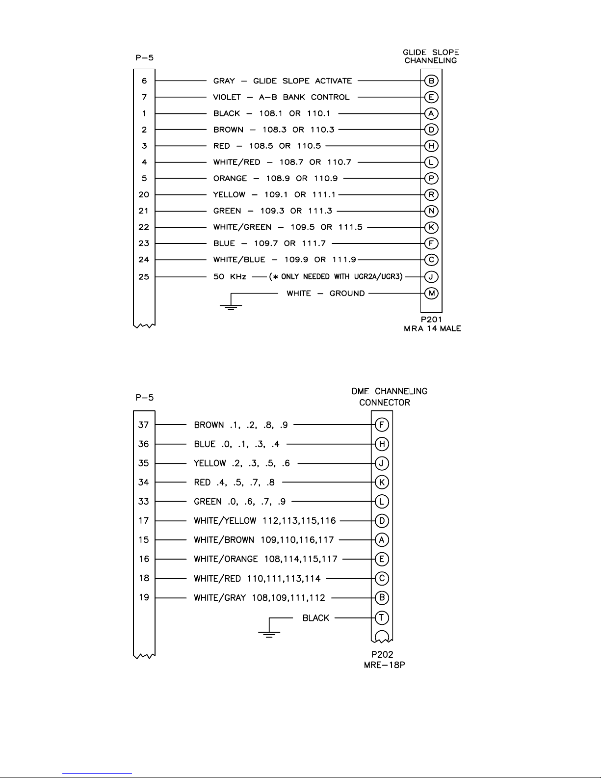
requiring Glideslope and/or DME channeling table 2-1 list the pin connections on P5.
To enable 2 of 5 Glideslope channeling pin 8 should be connected to ground. The
original Glideslope and DME channeling cables should be cut off the MK12(A/B)
and wired to P5 using a DB37 female connector ( supplied ). Refer to figures 2-2, and
2-3 for these channeling connections.
PIN # FUNCTION PIN # FUNCTION
1 108.1/110.1, A-MHZ 20 109.1/111.1, A-KHZ
2 108.3/110.3, B-MHZ 21 109.3/111.3, B-KHZ
3 108.5/110.5, C-MHZ 22 109.5/111.5, C-KHZ
4 108.7/110.7, D-MHZ 23 109.7/111.7, D-KHZ
5 108.9/110.9, E-MHZ 24 109.9/111.9, E-KHZ
6 G.S. ACTIVATE 25 50 KHZ
7 A/B 26 GROUND
8 2/5 ENABLE 27 ARINC
9 28
10 29 KEEP ALIVE
11 30
12 SWITCHED A+ 31 GROUND
13 32 50 KHZ
14 33 NARCO 'L', E-KHZ
15 NARCO 'A', E-MHZ 34 NARCO 'K', D-KHZ
16 NARCO 'E', D-MHZ 35 NARCO 'J', C-KHZ
17 NARCO 'D', C-MHZ 36 NARCO 'H', B-KHZ
18 NARCO 'C', B-MHZ 37 NARCO 'F', A-KHZ
19 NARCO 'B', A-MHZ
TABLE 2-1
P-5 FUNCTIONS