Narex Vhu 2 1/8" User manual

Instruction Manual
No.: 2420304
Vhu
Vhu
Universal Boring Heads
Vhu 2 1/8”, 3 1/8”, 4 7/8”, 6 ¼ ”
Producer:
Moskevska 63
101 00 Praha 10 – Vrsovice
Czech Republic
Phone: +420 246 002 249
Fax: +420 246 002 335
e-mail: [email protected]
www.narexmte.cz

2
OPERATING INSTRUCTIONS
Vhu 21/8”, 31/8”, Vhu 47/8” and Vhu 6 ¼ ” Universal Boring Heads.
Utilisation:
The Vhu 21/8”, 31/8”,Vhu 47/8” and Vhu 61/4” universal boring heads can be utilised for boring,
surfacing of front and rear facings, turning of external diameters, machining of external and internal
recesses and cutting threads. The Vhu 6 ¼ ” is same as Vhu 4 7/8” but slide here are with 5 holes
(not with 3 holes as for Vhu 4 7/8”).
By a combination of the automatic transverse feed motion of the tool slide with the motion of the
machine spindle it is possible to bore tapered holes, turn external tapers and cut tapered threads.
The taper angle depends in this case on the feed motion of the machine.
The universal boring heads widen considerably the machining possibilities of horizontal boring
machines, radial drilling machines and coordinate boring machines etc.
Examples of application:
No. of Operation Example
operation
1. Hole boring Fig. No. 1
2. Surfacing on small diameter front facing Fig. No. 2
3. Surfacing on large diameter from facing Fig. No. 3
4. Recessing in bore Fig. No. 4
5. Recessing on surface Fig. No. 5
6. External turning Fig. No. 6
7. Recessing of long shoulder Fig. No. 7
8. Taper boring Fig. No. 8
9. Surfacing on rear facing Fig. No. 9
10. Thread cutting Fig. No. 10

3
Fig. 4 Recessing in bore
Ød ØD
h
h
ØD
Fig. 1 – Hole boring
Ød ØD
Fig. 1 Ø d max. h max. Ø D max.
Vhu 2.1/8" 6 1/4" 4 1/4" 9"
Vhu 3.1/8" 8" 4 1/4" 11"
Vhu 4.7/8" 11" 7 1/4" 15"
Vhu 6.1/4" 13“ 7 1/4" 18“
Fig. 2 & 3 Ø d max. Ø D max. a max.
Vhu 2.1/8" 5 1/2" 13" 2 1/8"
Vhu 3.1/8" 7" 15" 3 1/8"
Vhu 4.7/8" 9 3/4" 24" 4 7/8"
Vhu 6.1/4" 11 3/4“ 27“ 6 1/4"
Fig. 2 – Surfacing on
small diameter front
facing
Ød
a
Fig. 3 Surfacing on
larger diameter front
facing
ØD
a
fig. 4 Ø d max. Ø D max. h max.
Vhu 2.1/8" 6 1/4" 13 3/4" 4"
Vhu 3.1/8" 8" 15 3/4" 4"
Vhu 4.7/8" 11" 25" 6 1/2"
Vhu 6.1/4" 13“ 28“ 6 1/2"

4
Fig. 7
Recessing of
long shoulder
h
Fig.5 Recessing
on surface
ØD
h
Fig. 6 External
turning
ØD
h
Fig. 5 & 6 Ø D max. h max.
Vhu 2.1/8" 10 3/4" 4"
Vhu 3.1/8" 12 3/4" 4"
Vhu 4.7/8" 20 1/2" 6 1/2"
Vhu 6.1/4" 23 1/2“ 6 1/2"
Fig. 7 h max.
Vhu 2.1/8" 4"
Vhu 3.1/8" 4"
Vhu 4.7/8" 6 1/2"
Vhu 6.1/4" 6 1/2"
Fig. 8 Taper boring
α/2 = 5º - 85º
α/2
Fig. 9
Surfacing on
rear facing
ØD
h
Fig. 10 Thread cutting
ØD
h
Fig. 5 & 6 Ø D max. h max.
Vhu 2.1/8" 12 1/2" 3 1/2"
Vhu 3.1/8" 13 1/2" 3 1/2"
Vhu 4.7/8" 21 1/2" 4"
Vhu 6.1/4" 24“ 4"

5
I. Boring and turning of external diameters.
When boring and turning external diameters the operator must avoid touching the breaking ring (1)
which could cause an alteration of the set dimension.
a) To achieve a rapid resetting of the tool slide (5) it is necessary to force an extension socket
spanner into the internal hexagon of the dial for rapid feed motion (12) to a depth of approx.
0,5 in. The tool slide can be now quickly traversed by turning.
One division of the dial for quick traverse of the tool slide stands for the following values:
Vhu 21/8” and 31/8” – feed motion of the tool slide by 0,04in = 0,08in on dia.
Vhu 47/8”and Vhu 6 ¼ ” – feed motion of the tool slide by 0,08in = 0,16 in on dia.
One turn of the screw for rapid feed traverse of the tool slide stands for the following values:
Vhu 21/8” and 31/8” – feed motion of the tool slide by 0,12in = 0,24 in on dia.
Vhu 47/8” and Vhu 6 ¼ ” – feed motion of the tool slide by 0,16in = 0,32in on dia.
After the slide has been reset, the quick traverse screw must be re-locked against turning. Pull
out the socket spanner partly so that a length of only 0,16on will remain on the hole, then turn
the screw in order to set the nearest scale line against the foxed scale mark of the tool slide
(5). Check by turning the spanner to both slides whether the screw is secured against turning.
b) To achieve a fine setting of the tool slide (5) it is necessary to turn the fine setting dial (4) by
means of a socket spanner. The turning of the dial (4) on the direction of the arrow will cause
the tool slide (5) to move also in the direction of the arrow.
One division of the fine setting dial (4) represents a feed motion of the tool slide (5) by
0,00025in = 0,0005in on dia.
When performing precise setting from a larger diameter to a smaller one, reverse the fine
setting dial by more than one half on a turn that would correspond to the dimension, and then
return to the dimension. This will eliminate the effect of tolerances in the transmission
(blacklash).
After the setting has been finished, lock the set dimension by means of the tool slide lock
screw (9). Slight tightening of this screw will help to eliminate the backlash during fine setting.
II. Surfacing on front and rear facings, recessing of external and internal recesses.
a) These operations require a transverse feed of the tool slide (5); the tool slide lock screw must
be loosened (9).
b) The Vhu 2 1/8”, 3 1/8”, 4 7/8” and 6 ¼ ” universal boring heads can be set to automatic
transverse feed of 0,0020, 0,0040, 0,0060 and 0,0080in/rev.

6
The feed is adjusted by turning the engagement ring (2) so that the dial division filled with red
paint will be set opposite the red paint filled hole of the respective number indicating the
magnitude of the transverse feed in 0,0001in/rev. on the automatic transverse feed dial (16).
The best way to engage the feed is to take the engagement ring by its indexed part between
the thumb and index finger of the one hand while taking the breaking ring 1) with engaged
clutch (15) between the thumb and index finger of the other hand, then setting required feed by
turning both rings against each other. An example of feed engagement is given in Fig. No. 11
which shows an automatic tool slide feed of 0,004in/rev.
Disengage the feed after the completation of all operations using the automatic tool slide feed.
For safety reasons engage the feed only with the machine at rest.
Table of recommended chip width values at surfacing on front facings.
The Table applies to steel of 7X10⁴– 11,5X10⁴/lbs per sq/in tensile strength. For cast iron of a
hardness HB 180 – 220 the recommended values are doubled.
To engage the required transverse feed turn the braking ring (1) with the machine at rest
against the direction of the spindle rotation by at least one turn! (Maximum speed = 500 r. p.
m.)
c) The automatic transverse feed of the tool slide (5) will be engaged by slowing down the control
ring (3) with the aid of the braking ring (1). Into the hole of the braking ring a holding rod (17)
should be inserted and held by hand only for the duration of short-term simple jobs. When
surfacing on wider areas by larger chips and whenever stops are used, it is necessary – for
safety reasons – to support the rod by means of a positive stop situated conveniently near the
machine spindle. In both cases the braking ring (1)
d) must be connected with the control ring (3) by means of the clutch (15) situated in the braking
ring (1) which should be forced with the finger into one of the two slots in the control ring.
Type Transverse
feed
Max. dia. of
surfaced
facing
Max. chip
width
Max.dia. of
surfaced
facing
Max.
chip
width
0,004 1/8" 5/64"
Vhu 2
1/8" 0,008 4 3/4" 5/64" 13" 1/16"
0,004 1/8" 5/64"
Vhu 3
1/8" 0,008 6 1/4" 5/64" 15" 3/64"
0,004 5/32" 5/64"
Vhu 4
7/8" 0,008 8" 1/8" 24" 3/64"
0,004 1/8" 4/64"
Vhu 6
1/4" 0,008 9" 5/64" 27" 2/64"
Fig.11

7
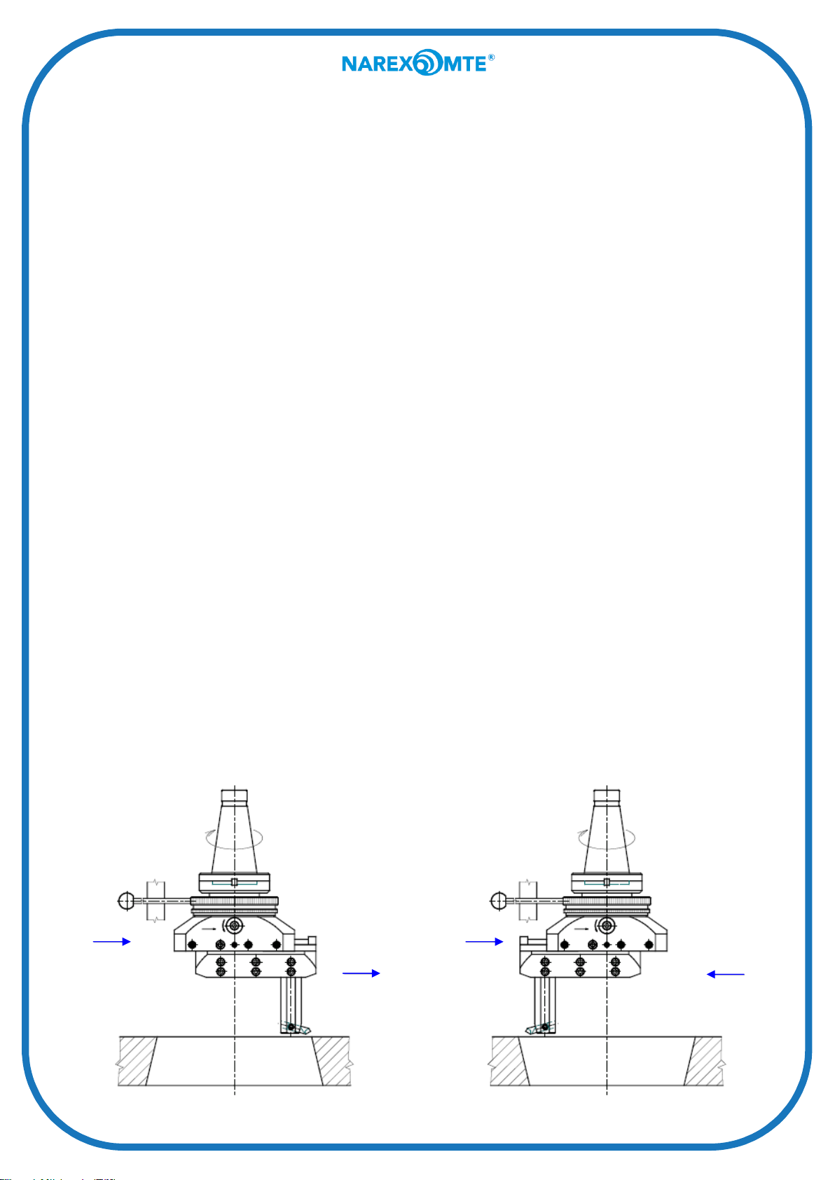
e) By slowing down of the control ring (3), when the head is turning to the right, the tool slide (5)
moves in the direction of both arrows situated on the tool slide side near the fine feed setting
dial (4); when the head is turning to the left, the tool slide moves against the direction of the
arrows.
f) An automatic disengagement of the transverse feed takes place when one of the trip dogs (10)
strikes the trip dog pin (11) or when the cutting resistance increases due to a large cut,
blunting or chipping of the tool. The sensitivity of the clutch disengagement (15) can be
adjusted by the adjusting screw (14) which compresses or relieves the spring of the clutch
(15). In case of excessive screwing-in of the clutch adjusting screw (14) try to disengage the
clutch by means of screw driver (as shown in Fig. No. 12). If the clutch cannot be completely
disengaged, the spring coils bear on each other and the clutch adjusting screw (14) must be
slightly loosened; then repeat the disengagement of the clutch (15) by the described method.
g) Adjustment of trip dog for disengagement on accurate diameter. The trip dog (10) must be
adjusted and secured so as to disengage the transverse feed at the moment the tool cutting
edge reaches a certain diameter. The disengagement of the clutch (15) must be therefore
adjusted so that the disengagement pressure between the trip dog and trip dog pin (11) be as
small as possible, i. e. the clutch adjusting screw (14) must be screwed in as little as possible.
In spite of this, however, there will be a certain overtravel exceeding the required dimension.
This overtravel is within the tolerance of the recess diameters for lock rings. A more accurate
adjusting for precision jobs can be attained by the following trip dog adjustment:
A) The trip dog (10) must be adjusted and firmly tightened so as to disengage shortly
before the required diameter will be attained, e. g. by turning the fine setting dial (4)
reverse the tool slide by approx. 0,008 inch push the trip dog (10) against the trip dog
pin (11) and secure firmly by screws.
The difference between the required and actual diameter will be measured after a
trial disengagement.
B) Now, the trip dog should be adjusted as follows:
a) Do not loosen the trip dog (10) but reverse the tool slide (5) so that a feeler gauge of
any type, for example 2 mm, can be slipped between the trip dog and trip dog pin
(11).
b) Secure the tool slide (5) against moving by means of the tool slide lock screw (9) so
that its position can be changed when displacing the trip dog (10).
c) A new slip gauge will be assembled as follows:
1. If the actual diameter which has been attained after a trial disengagement is
larger than the required diameter, the new feeler gauge must be smaller by
50% of the ascertained difference.
2. If the actual diameter is smaller than the required one, the new feeler gauge
must be enlarged by 50% of the ascertained difference.
Fig.1
2

8
d) Now loosen the trip dog (10) and push ir against the newly assembled feeler gauge
abutting on the trip dog pin (11); then push the trip dog against the gauge and tighten
firmly.
e) Remove the trip dog and loosen the tool slide lock screw (9). The disengaging of the
automatic transverse feed is vow set to the required diameter.
After the trip dog has been reached, the deflected mechanism must be released by a
few turns of the dial for fine setting of the tool slide (4). Only than may the tool slide
be reversed by means of the quick traverse dial (12).
III. Taper boring
For taper boring the transverse feed of the tool slide must be coupled to the axial feed of the
machine spindle.
a) Determining of the tool slide and spindle feed in relation to the taper angle. The required tool
slide and spindle feed for the respective taper angle can be determined from the taper boring
chart (see enclosure) which shows that for the required taper angle of 70º a slide feed of
0,0020 inch/rev. and a machine feed of 0,00286 inch/rev., or for the tool slide feed of 0,0040
inch/rev. a machine feed of 0,00572 inch/rev. can be selected.
According to the chart also the feed of the machine spindle in mm/min in relation to the spindle
speed (in r. p. m.) can be determined. It is necessary to select the smallest possible values of
the machine spindle feed, but in case of small angle taper boring relatively large feeds, which
lower the surface quality, are unavoidable. There are unevenesses of 0,0010in.on the taper
surface caused by the interrupted transverse feed. Generally, the necessary feeds for the
required tapers will not be provided by the machine so that deviations in the taper ratio will be
unavoidable.
Therefore, an additional calibrating of the taper by means of another instrument is necessary.
b) Tool clamping:
In the case of clockwise spindle rotation the feed of the tool slide (5) can be effected only in
one direction (see Fig. No.13). In spite of this, expanding or narrowing tapers can be bored.
Fig.1
3
Direction
of the tool
slide
transverse
feed
Feed into
cut Feed
into cut
Direction
of the
tool slide
transver
se feed

9
If the tool is clamped on the direction of the transverse feed of the tool slide, an expanding
taper will be bored. If the same tool is clamped in the direction opposite to that of the
transverse feed of the tool slide, a narrowing taper will be bored. When clamping the tool, be
sure to set its point in the plane passing through the axes of the holes for rods and holders (7)
– (see Fig. No. 14), otherwise the taper will not be accurate.
c) Taper boring procedure:
1. Clamps the tool according to paragraph b) and by means of the dial for the tool slide quick
traverse (12) and the tool slide fine setting dial (4) set the tool to the initial boring diameter.
2. Advance the spindle so that the tool cutting edge is approx. 0,09 in above the surface of
the workpiece and set the tool slide dial in this position to zero.
3. Withdraw the spindle by a few millimeters and advance to zero by the spindle feed
determined from the chart. Stop the machine when reaching zero, but do not disengage
the feed.
4. Adjust the trip dog according to Fig. No. 13 and tighten.
5. Engage the clutch (15) and screw in completely the clutch adjusting screw (14). Thus the
disengagement of the clutch (15) in case of overloading is excluded. Accordingly,
increased attention is necessary during operation.
6. Insert holding rod (17) into the hole in the braking ring (1) and support it by the positive
stop on the machine.
7. Start the machine. Now tool slide (5) moves simultanously with the moving machine
spindle and forms the required taper.
8. After completation of the job remove the holding rod (17), return the boring head into its
original position and cut another chip by means of the trip dog (10) and gauge or dial (4).
This procedure will be repeated as required. External tapers can be machined by a similar
method.
IV. Thread cutting
The braking ring (1) must be caught when cutting threads as this could cause an axial motion of
the tool slide (5).
Working procedure:
1. Mount the tool.
2. Engage the respective feed corresponding to the head of the thread.
3. Traverse the tool slide by means of the dial for quick traverse of the tool slide (12) and cut
the chip by means of the dial for fine setting of the tool slide (4).
4. Start machine, cut the thread and stop the machine.
5. Withdraw the tool by means of the dial (12) or dial (4).
6. Cut another chip and repeat the whole procedure as required.
Fig.1
4

10
Also taper threads can be cut with the Vhu 21/8”, 31/8”, Vhu 47/8” and Vhu 6 ¼ ” boring heads.
The axial feed for the lead of the thread is effected by the machine spindle and the transverse
motion of the tool slide effects the thread cutting. Both feeds must be permanently engaged
during thread cutting. The transverse feed of the tool slide will be calculated by means of the
following formula:
Transverse feed of the tool slide in in/rev. = (lead of the thread in in) / (cotg α/2)
The tool clamping and setting to the required diameter is the same as in the case of taper
boring.
Lubrication:
The internal mechanism of the boring heads is lubricated by means of a grease gun and two
nipples (13). The design of the Vhu universal boring heads is protected by the Czech Patent
No. 105957.
V. Tools
Vhu 6 ¼ “
Vhu 6 ¼ “
Vhu 6 ¼ “
Vhu 6 ¼ “

11
We are confident that the Vhu 21/8”, 31/8”,Vhu 47/8” and Vhu 6 ¼ ” universal boring heads will
enable you to perform the most accurate and intricate operations on your boring machines.
The Vhu 21/8”, 31/8”, Vhu 47/8” and Vhu 6 ¼ ” universal boring heads enable a large number
of various operations which, however, require a wide choice of tools, which – in the majority of
cases – will not be utilised. Therefore, along with each Vhu boring head the above specified
tool bits are supplied as standard accessories. Tools for recessing, thread cutting and other
special jobs can be made by grinding from semi – products 5/16” x 6/16” x L (for Vhu 21/8”,
31/8”) or 3/8” x 3/8” x L (for Vhu 47/8” and Vhu 6 ¼ ”).
By using two reducing sleeves supplied as standard accessories it is possible to work with all
types of standard tools with a circular cross section shank of 3/4” and 5/8” dia.
VI. Description
1. Braking ring 9. Tool slide lock screw 17. Holding rod
2. Engagement ring 10. Trip dog 18. Flange
3. Control ring 11. Trip dog pin
4. Tool slide fine setting dial 12. Dial for quick traverse of tool slide
5. Tool slide 13. Lubrication nipple
6. Adjusting screw 14. Clutch adjusting
7. Holes for rods and holders 15. Clutch
8. Lock screw 16. Automatic transverse feed dial

12
VII. Exchangeable Clamping Taper Shank

13
Diagram for taper boring with Vhu 2 1/8“, 3 1/8“, 4 7/8“ and 6 ¼ “

14

15

16
This manual suits for next models
4
Table of contents