NARGESA CC60 User manual

INSTRUCTIONS BOOK
PRADA NARGESA, S.L
Ctra. de Garrigàs a Sant Miquel s/n · 17476 Palau de Santa Eulàlia (Girona) SPAIN
Tel. +34 972568085 · [email protected] · www.nargesa.com
2-AXIS POSITIONER LIMIT
NON-MANDREL PIPE BENDER CC60

Thank you for choosing our machines
www.nargesa.com

INSTRUCTIONS BOOK FOR PIPE BENDER LIMIT CC60 2
CONTENTS
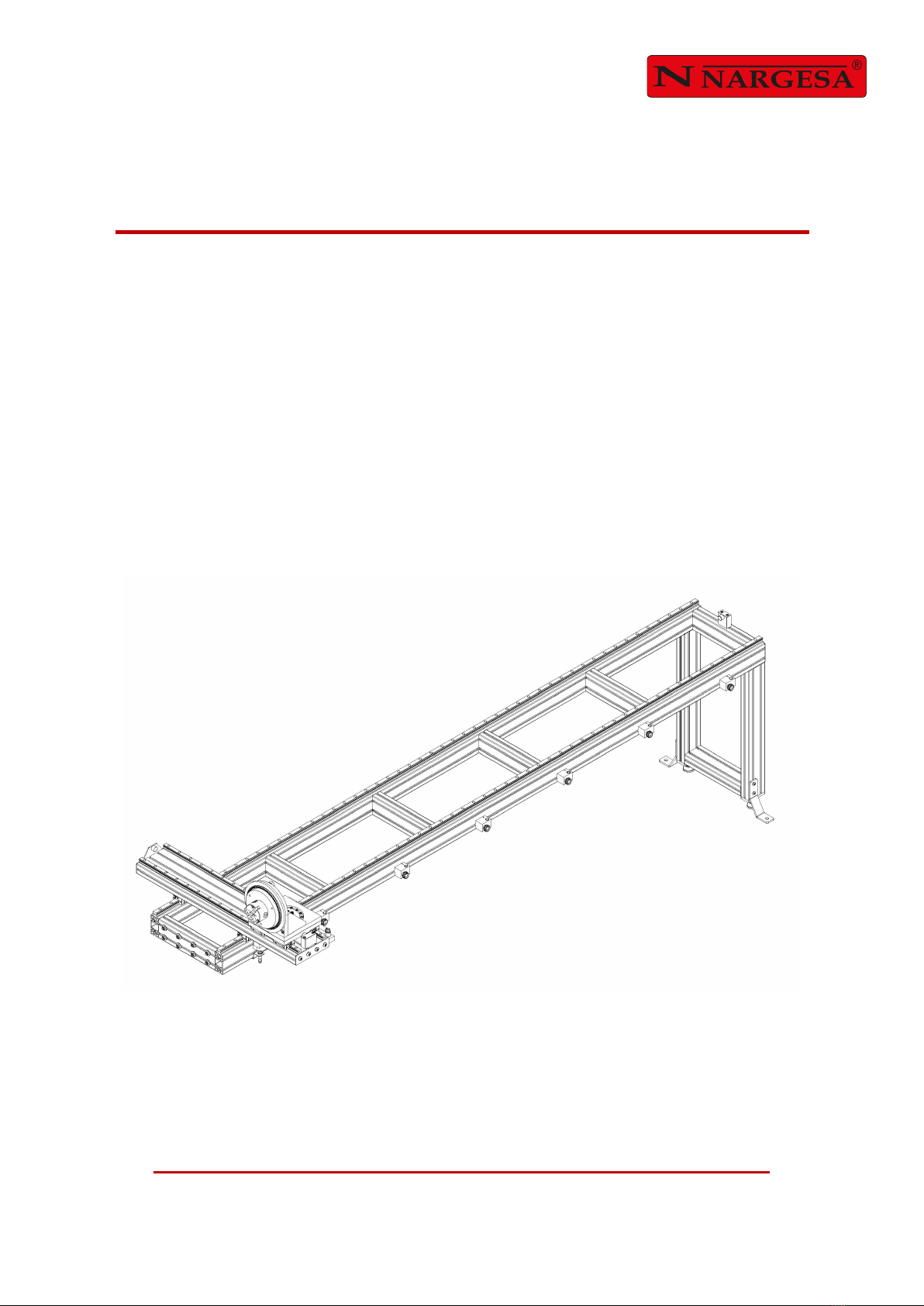
1. ACCESSORY DETAILS ............................................................................................................ 3
1.1. Accessory Identification ................................................................................................ 3
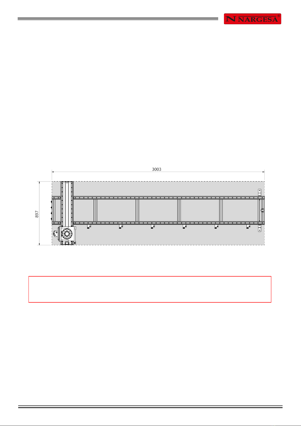
1.2. Dimensions ................................................................................................................... 3
1.3. Accessory Description .................................................................................................. 4
1.4. General Characteristics ................................................................................................ 4
1.5. Machine Parts ............................................................................................................... 5
2. TRANSPORT AND STORAGE ................................................................................................. 6
2.1. Transport ....................................................................................................................... 6
2.2. Storage Conditions ....................................................................................................... 6
3. MAINTENANCE ......................................................................................................................... 7
3.1. Greasing the Moving Parts ........................................................................................... 7
4. LIMIT LOCATION AND INSTALLATION .................................................................................. 8
4.1. Limit Location ................................................................................................................ 8
4.2. Dimensions and Work Area ......................................................................................... 8
4.3. Acceptable External Conditions .................................................................................... 8
4.4. Installing the Limit ......................................................................................................... 9
4.5. Adjusting the Limit ....................................................................................................... 16
5. INSTRUCTIONS FOR USE ..................................................................................................... 19
5.1. Limit Features and Use ............................................................................................... 19
5.2. Securing the Pipe to the Limit ..................................................................................... 19
5.3. Installing the Through Pipe ......................................................................................... 19
5.4. Adjusting the Longitudinal Limits ............................................................................... 20
5.5. Adjusting the Cross Limit ............................................................................................ 21
5.6. Adjusting the Pipe Rotation Angle .............................................................................. 22
TECHNICAL ANNEXES

INSTRUCTIONS BOOK FOR PIPE BENDER LIMIT CC60 3
Make NARGESA
Type of accessory 2-axis positioner limit
Model CC60
1. ACCESSORY DETAILS
1.1. Accessory Identification
1.2. Dimensions
Figure 1. Outside dimensions of Pipe Bender Limit CC60

INSTRUCTIONS BOOK FOR PIPE BENDER LIMIT CC60 4
Reference 140-17-01-50000
Max. size round steel pipe 60.3 mm or 2" Schedule-40 or 2" Gas x 4 mm.
Max. size round steel through pipe 42.4 mm or 1 1/4”
Max. angle of curvature -180º / 0º / 180º
Dimensions 3003 x 897 x 1131 mm
Weight 125 Kg
PRADA NARGESA S.L is not liable for any damages that may be caused due to improper use or a
breach of the safety rules by users.
1.3. Accessory Description
The Non-Mandrel Pipe Bender Limit CC60 is an accessory specifically designed to position the pipe or
profile during bending.
The CC60 limit makes it possible to produce serial parts faster with more precision and repetitiveness.
• Adjustable longitudinal positioning with 6 positions
• Angular head rotation every 5 degrees
• Adjustable four-hook tray for round and square pipes
• Longitudinal movement with high-precision linear guides
• Automatic anti-collision control
• Easy handling and preparation for complex parts
1.4. General Characteristics

INSTRUCTIONS BOOK FOR PIPE BENDER LIMIT CC60 5
1.5. Machine Parts
Longitudinal cart
Floor securing part
Adjustable
stopper
Cross limit
Cross cart
Vertical
support
Adjustment guide
Clamps
Pipe
securing
tray
(Longitudinal
limit switch
sensor
(inductive)

INSTRUCTIONS BOOK FOR PIPE BENDER LIMIT CC60 6
2. TRANSPORT AND STORAGE
2.1. Transport
The limit should be moved as follows:
- Along the bottom through the pallet at the base of the box using a forklift or lift truck as indicated in the
illustration. Never raise the limit more than 200 mm off the ground or it may tip over.
Figure 4. Moving the Limit
2.2. Storage Conditions
The Pipe Bender Limit may not be stored anywhere that does not meet the following requirements:
- Moisture of 30-95%
- A temperature of -25 to 55ºC or 75ºC over periods not to exceed 24 hours (please remember these
temperatures are for storage conditions)
- Do not pile heavy objects on top

INSTRUCTIONS BOOK FOR PIPE BENDER LIMIT CC60 7
ATTENTION: To grease the Limit, you must stop the machine and press the “Emergency Stop”
button.
3. MAINTENANCE
3.1. Greasing the Moving Parts
Keeping the moving parts on the limit clean is recommended to ensure proper operation and extend the
service life.
To grease the limit skids on the CC60, simply grease all the limit greasers: 8 in all, every 30 days .
Front view
Rear view

INSTRUCTIONS BOOK FOR PIPE BENDER LIMIT CC60 8
ATTENTION: The limit moves while the machine does the bending. Do not place anything in the
Limit work area that may obstruct its movement.
4. LIMIT LOCATION AND INSTALLATION
4.1. Limit Location
Try to position the machine and limit in the proper location so they do not have to be moved; otherwise,
follow the steps described in the Transport section (no. 2). Position over a smooth, level surface to prevent
vibrations and movements during bending operations .
4.2. Dimensions and Work Area
Take the dimensions, limit work area and the lengths of any part to be worked into consideration when po-
sitioning the limit.
The pipe bender may be used by a single operator who must stand on the side of the limit to manage the
adjustable stoppers and the pipe securing tray.
Before starting the bending process, the operator shall adjust the limit and secure the material while the
machine is off.
Figure 6. Limit Work Area
4.3. Acceptable External Conditions
- A room temperature of +5ºC to +40ºC without exceeding an average temperature of +35ºC over 24 hours.
- Moisture of 30-90% without water condensation.

INSTRUCTIONS BOOK FOR PIPE BENDER LIMIT CC60 9
4.4. Installing the Limit
1. Install the vertical limit support by inserting it into the guides on the end and screw in.
2. Screw in the vertical support using the four screws.
3. Install the guide covers by firmly pressing. Use a plastic hammer if necessary.

INSTRUCTIONS BOOK FOR PIPE BENDER LIMIT CC60 10
4. Unscrew and remove the rear cover from the machine. Install the limit on the side of the machine
indicated in the image. Remove the 8 screws supplied with the machine and screw the limit to it using the
8 screws supplied with the limit.
5. Pull the end of the inductive sensor cable from the inside towards the outside of the machine through the
top of the shelf.
ATTENTION: To secure the limit to the machine, you must stop the machine and press the
“Emergency Stop” button.

INSTRUCTIONS BOOK FOR PIPE BENDER LIMIT CC60 11
6. Level the machine on the two axles.
7. Level the limit on the two axles.

INSTRUCTIONS BOOK FOR PIPE BENDER LIMIT CC60 12
8. Adjust the height of the vertical support using the two adjustable legs, adjusting the limit to a level posi-
tion.
9. Check that the limit is completely level before definitively securing it to the machine by tightening the 8
screws well.

INSTRUCTIONS BOOK FOR PIPE BENDER LIMIT CC60 13
10. Secure the two securing parts supplied with the limit to the ground.
11. Put on the rear cover and screw in the 8 screws.

INSTRUCTIONS BOOK FOR PIPE BENDER LIMIT CC60 14
12. Connect the machine inductive sensor cable by tightening it with the limit inductive sensor.
13. Place the inductive sensor in the limit chassis support and secure it with the bolt. Start the machine
using the power switch.
14. Slide the longitudinal cart until the inductive sensor LEDs turn off. This means it was detected. Make
sure the clamps do not collide with the machine in this cart position.

INSTRUCTIONS BOOK FOR PIPE BENDER LIMIT CC60 15
15. The following message appears on the control screen. Press x so it will disappear.
16. Press to access the menu, then press . Enter the password.
17. Access the E/S menu and activate the backgauge limit switch. Press to return to the home
screen. When the inductive sensor is working, the machine will automatically stop as soon as the
longitudinal cart reaches this limit to prevent the cart from colliding with the machine.

INSTRUCTIONS BOOK FOR PIPE BENDER LIMIT CC60 16
4.5. Adjusting the Limit
The bender switch CC60 is adjusted by our technicians before the machine is sent to the customer. How-
ever, you need to check and re-adjust the limit before working with it.
1. Insert a pipe measuring 1200 mm minimum in the limit as indicated in section 5.2. Securing the Pipe to
the Limit. Use a marker to make a mark at 1000 mm on the other end of the pipe and place it in the
main roller.
2. Place one of the adjustable stoppers at 100 mm and secure it.

INSTRUCTIONS BOOK FOR PIPE BENDER LIMIT CC60 17
3. Adjust the longitudinal cart with the stopper and loosen the screws in the adjustment guide.
4. Move the cart slowly until the mark on the pipe is lined up with the mark on the counter-shape and the
main roller. Make sure the longitudinal cart and the stopper are still connected.

INSTRUCTIONS BOOK FOR PIPE BENDER LIMIT CC60 18
5. As soon as the mark on the pipe is lined up, tighten the screws on the adjustment guide and remove the
pipe.

INSTRUCTIONS BOOK FOR PIPE BENDER LIMIT CC60 19
5. INSTRUCTIONS FOR USE
5.1. Limit Features and Use
The CC60 limit is used to position the pipe in an exact position for bending.
5.2. Securing the Pipe to the Limit
Secure the pipe to the securing tray by adjusting the clamps using the wrench supplied with the limit. Make
sure the material is completely secured to the tray and in contact with the base of the tray.
To release the pipe, loosen the clamps using the wrench until the tray comes loose.
5.3. Installing the Through Pipe
If you use a pipe that is longer than 3000 mm, use the central opening on the securing tray so the material
goes through it.
To install the through pipe, unscrew the two securing screws from the plate on the back of the securing
tray .
Other manuals for CC60
2
Table of contents
Other NARGESA Construction Equipment manuals
Popular Construction Equipment manuals by other brands

Epiroc
Epiroc Flexi ROC T20 R Maintenance schedules

Conquip
Conquip Trench Box user guide

Ligchine
Ligchine Screedsaver BOSS 240 instructions

Fayat Group
Fayat Group BOMAG BF 800 C Service manual

Discount Equipment
Discount Equipment MULTIQUIP Mikasa Series Operation manual

probst
probst SG-60-PGL2 operating instructions