manuals.online logo
Brands
  1. Home
  2. •
  3. Brands
  4. •
  5. Nasaco
  6. •
  7. Scale
  8. •
  9. Nasaco Cassini 1/37 User manual

Nasaco Cassini 1/37 User manual

Popular Scale manuals by other brands

KERN MCC-M operating instructions

KERN

KERN MCC-M operating instructions

Little Balance SB MECA 8113 user manual

Little Balance

Little Balance SB MECA 8113 user manual

Fitbit Zip Aria Wi-Fi Smart Scale user manual

Fitbit Zip

Fitbit Zip Aria Wi-Fi Smart Scale user manual

KERN MPU 250K100 operating instructions

KERN

KERN MPU 250K100 operating instructions

Steinberg Systems SBS-PF-200 user manual

Steinberg Systems

Steinberg Systems SBS-PF-200 user manual

Total TP2000 user guide

Total

Total TP2000 user guide

A&D HL-200i operating instructions

A&D

A&D HL-200i operating instructions

OHAUS Courier 3000 user guide

OHAUS

OHAUS Courier 3000 user guide

Scarlett SC-KS57P97 instruction manual

Scarlett

Scarlett SC-KS57P97 instruction manual

BASETech LS-40S operating instructions

BASETech

BASETech LS-40S operating instructions

SR Instruments SR Scales SR565i-H Operating and service manual

SR Instruments

SR Instruments SR Scales SR565i-H Operating and service manual

Gallet PEP 301ART instruction manual

Gallet

Gallet PEP 301ART instruction manual

AWS ZEO-50 user manual

AWS

AWS ZEO-50 user manual

Gima Glass Body Fat Analyzer Use and maintenance book

Gima

Gima Glass Body Fat Analyzer Use and maintenance book

Seca 374 user manual

Seca

Seca 374 user manual

EDLUND BBPZ-20 quick start guide

EDLUND

EDLUND BBPZ-20 quick start guide

TEC TEC SL59 SERIES owner's manual

TEC

TEC TEC SL59 SERIES owner's manual

Alecto ACW-40 user manual

Alecto

Alecto ACW-40 user manual

manuals.online logo
manuals.online logoBrands
  • About & Mission
  • Contact us
  • Privacy Policy
  • Terms and Conditions

Copyright 2025 Manuals.Online. All Rights Reserved.

Educational Brief
Cassini Spacecraft 1/37 Scale Model
Educational Product
Educators
& Students Grade 9
thru Adult
Learn by Building a Highly Detailed 1/37 Scale Model of the
Cassini Spacecraft
The Cassini Spacecraft is the largest interplanetary robot ever flown. Launched October
15, 1997, Cassini’s mission is to orbit Saturn, deliver the Huygens Probe to Titan’s
atmosphere, and spend at least four years studying Saturn’s atmosphere, magnetosphere,
icy satellites, its largest satellite Titan, and of course its ring system. Too massive to fly
directly to Saturn, Cassini orbits the Sun twice, flying by Venus and Earth, to gather the
momentum for its trip to the outer solar system. Jupiter provides the final boost to Saturn.
You can keep up with Cassini’s flight, and learn more about the mission, and about Saturn
and Titan, by visiting the Cassini Web Site. This model is also available there, to download
directly, as well as a much simpler model version at 1/40 scale:
http://www.jpl.nasa.gov/cassini
The Cassini 1/37 Scale Model is made by following the assembly instructions, cutting
out the printed parts, folding and gluing. The project requires several hours, and a good deal
of patience. By building the model, you’ll learn all about the Cassini Spacecraft, in an
effective, enjoyable way.
One model can be assembled by several people as a group activity. Numbered assembly
instruction steps marked “•” can be accomplished at the same time, so more than one person
can work together. Or one person working alone may do one “•” step while waiting for glue to
dry on another “•” step. If more than one person is working, each person should explain what
was learned about the spacecraft during their work, to the rest of the group.
The following pages contain everything you’ll need to build your Cassini Model.
Cassini 1/37 Scale Model Assembly Instructions v 3.1
This scale model of the Cassini spacecraft, with Huygens Probe, is designed for anyone interested, although it might
be inappropriate for children younger than about ten years of age. Children should have adult supervision to assemble
the model.
A. YOU’LL NEED THE FOLLOWING:
❐A good pair or scissors.
❐An art knife, such as X-ACTO #11, with a sharp new blade. Children must have adult supervision, of course, to use an
art knife. You'll also need a cutting surface such as a linoleum pad, or thick chipboard, when using the art knife. Use
caution: one can hurt oneself, or the furniture, with an art knife.
❐Wooden toothpicks for applying glue.
❐Glue. Use regular white glue (Elmer’s Glue-All® or equivalent). You might also try a thick white glue, sold in art and fabric
stores, called “TACKY GLUE” (Aleen’s or equivalent). Also, for the High-Gain Antenna (HGA), you'll need a low-
moisture glue, such as a glue stick.
❐A popsicle stick to help with assembly.
❐A beverage cup, preferably a heavy ceramic cup or mug, for supporting parts during assembly.
❐A thin clear sheet such as that used for making overhead transparencies. This will be used to fashion a stand for your
model. You can instead use a small, clear plastic beverage cup with a hole cut in the bottom.
❐A round pencil or dowel to wrap curvature into some parts.
❐A metal ruler to use as a straight edge.
❐A small pair of long-nose pliers to reach and squeeze some parts together while they glue. Small metal paper clamps
may also be useful to hold parts together while glue dries.
❐Space. Set up a well lighted, comfortable work area, with room to set glued parts to dry.
❐Time. Don't hurry. Plan to spend several hours for assembly. About 6 hours would probably be minimum if you
concentrate solely on assembly. It can easily be done in shorter steps, however, over a period of several days.
❐Patience. There may be trying times. But remember that extra care, and time, will pay off with a surprisingly accurate
representation of the Cassini spacecraft.
❐Optional: Rigid wire for the RPWS antennas. If your use of the model would present no danger of eye injury, you might
consider getting some thin, stiff brass or steel wire from a hobby store. Half a meter, or a couple of feet, should be
enough.
❐Optional: A straight pin which has a small metal head, for use in a science instrument.
❐Optional: Gold leaf, or imitation gold leaf, to apply to the Huygens Probe shield. You'll need spray-glue to apply it.
❐Optional: As you read through these instructions, you'll see that intersecting planes are used to simulate 3-
dimensional objects like tanks and rocket engines. You might wish to do some creative searching for different objects
to replace them, and increase the realism of your model. The High-gain Antenna (HGA) paper cone might also be
replaced by a small curved bowl-shaped object painted white.
B. BEFORE BEGINNING ASSEMBLY:
❐Read all of these instructions. Compare model parts with images. Examine the six Parts Sheets and read the
names of all the parts.
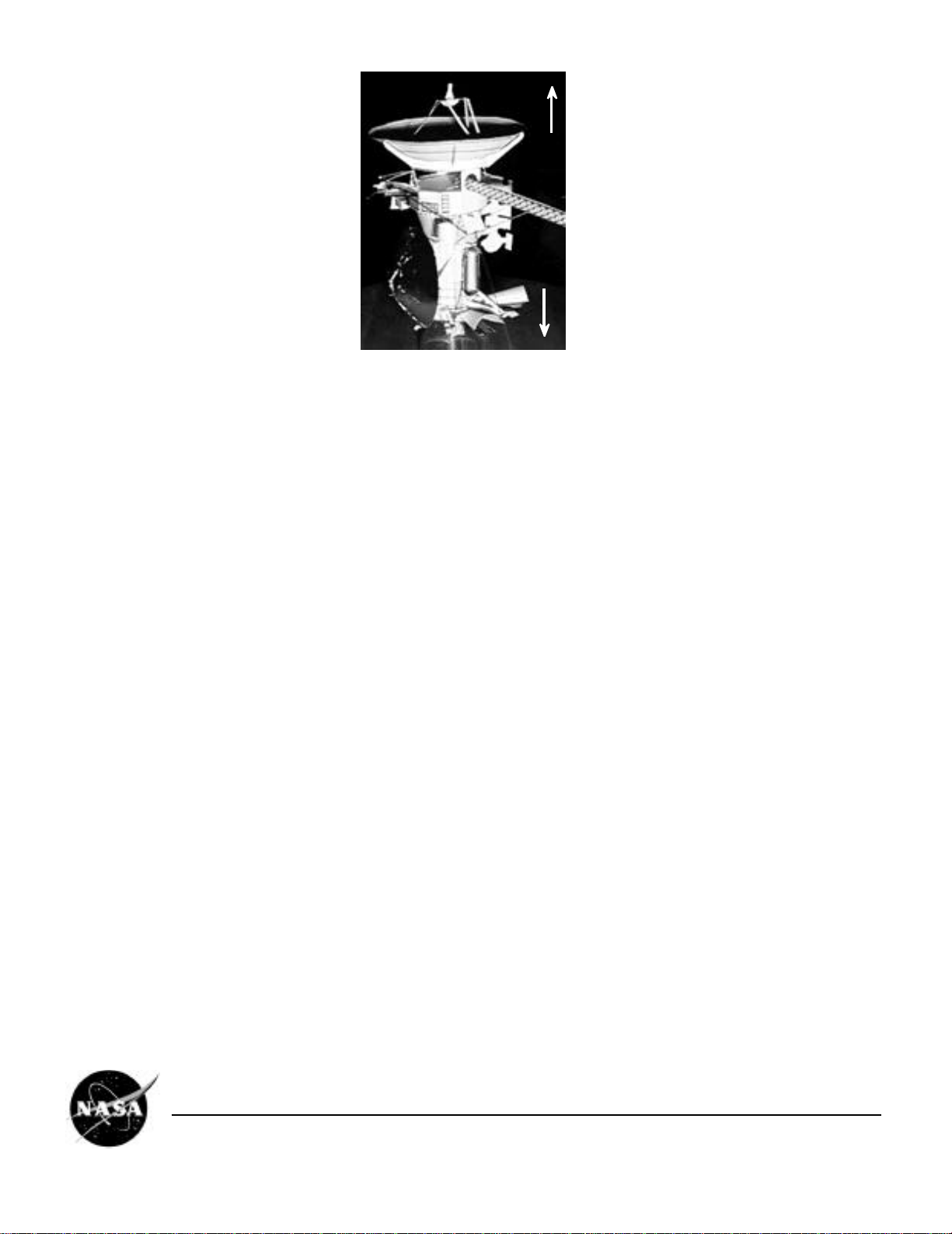
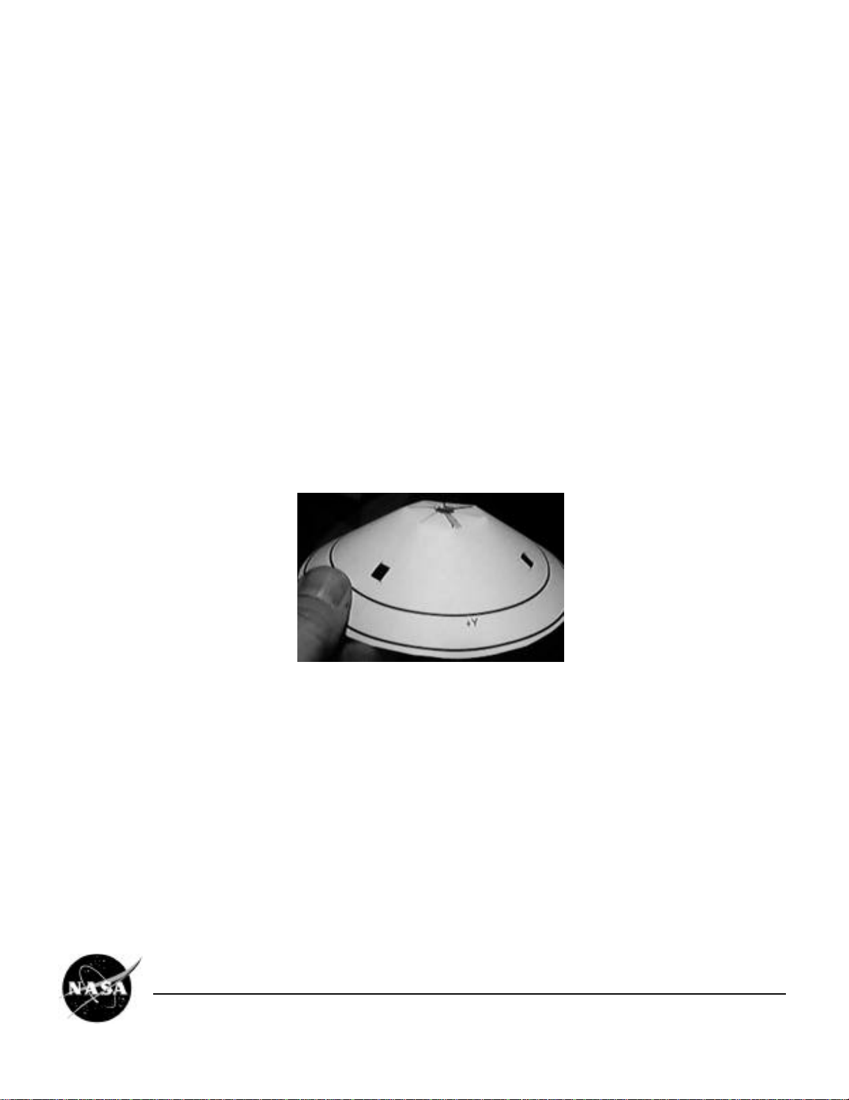
❐Get your bearings: this diagram defines "up," "down," etc. for the purpose of assembly. This will be the reference when
words such as "top" and bottom" are used to describe sides of parts. Also, during assembly, you'll notice that the
spacecraft's axes are indicated. These three imaginary lines pass through the center of mass of the spacecraft, and are
labeled X, Y, and Z. The Z axis goes up and down; down, in this picture, is "plus Z" (+Z). The general directions for the X
and Y axes are indicated on the parts. The axis directions can also be used to point to a side of the spacecraft, for
example, the -Z side of the spacecraft is where the High-Gain Antenna dish is mounted.
Cassini Spacecraft 1/37 Scale Model EB-1999-04-001-JPL
Page 2
INBOARD means toward the center ,
OUTBOARD means outward from center
UP
DOWN
C. IN GENERAL:
❐Sections marked with a • may be accomplished at the same time if two or more people are working on assembly, or if you
wish to work on one section while glue dries on another. In fact these steps were performed separately in building the
actual spacecraft. For example, the Propulsion Module was being built at Lockheed-Martin in Denver while the
Spacecraft Bus was being built at JPL in Pasadena, and the HGA was being built in Italy.
❐What to cut out? Each part is drawn against a shaded background. This shading appears grey when printed on a black &
white printer. Each part should be completely cut away from its shaded background. Some parts have areas within them
of shaded grey. These areas should be cut out of the part. Spacecraft details are printed on most of the parts. Don’t
confuse these with background shading. If there's any question, look at it on a color computer monitor: all the
background shading appears blue: if it isn't blue, don't cut it away.
❐When you finish cutting out a part, flatten it.
❐If an instruction doesn't say which way to fold something, fold in either direction.
❐When instructed to fold a part, consider scoring it first. To do this, line up a metal ruler or straight edge along the line to
be folded, and very lightly scratch it with an art knife, only breaking the surface of the card stock. You have to be very
careful not to cut through if you do this. While this is more time consuming, it will result in much neater folds, and may
help the parts fit together properly.
• 1. ASSEMBLE THE SPACECRAFT BUS
❐Cut out the SPACECRAFT BUS from Parts Sheet 1. Be sure to cut out the shaded areas above BAY 1, BAY 7, and
BAY 4.
❐Put a crease into each of the vertical black lines where the twelve sections are joined, folding the BUS into a ring with
the printing on the outside.
❐Smear glue on the square marked GLUE. Overlap the other end onto the glue to complete the ring. Make sure it's
straight, and squeeze the pieces together.
❐Fold down the tabs marked IRU, towards the center of the ring. IRU stands for Inertial Reference Unit, which will be
installed here later. Do the same to each of the six remaining similar tabs along the top of the BUS. Leave the four larger
tabs standing.
❐Cut out the BUS TOP from Parts Sheet 1. Smear glue on the area marked GLUE, and position it up inside the BUS so
that the eight folded tabs will contact the glue. Press the tabs down so they will glue securely.
Cassini Spacecraft 1/37 Scale Model EB-1999-04-001-JPL
Page 3
❐Fold over the twelve small tabs around the bottom of the BUS toward the inside. Leave them at about 90° to the bus.
Set the BUS upside down on your work surface.
❐Cut out the BUS BOTTOM from Parts Sheet 1. Be sure to remove the central shaded circle. Smear glue on the area
marked GLUE. Place the glued surface down onto the twelve folded tabs. You might want to reach inside with a pair of
long-nose pliers and squeeze the tabs to the BUS BOTTOM to glue securely.
❐Cut out one INERTIAL REFERENCE UNIT (IRU) from Parts Sheet 1. Fold back the two triangular sections away from the
printing. Fold back the section marked GLUE in the same direction. Adjust so all sections are perpendicular, and secure
with glue to hold their positions.
❐Smear some glue on the section marked GLUE of the IRU. Place this down on top of the BUS, with the area marked
GLUE covering the letters IRU on the BUS. The triangular sections point in toward the center of the BUS. Slide the IRU
outward so it hangs out over the BUS about half the width of the GLUE-marked section.
❐Cut out the other INERTIAL REFERENCE UNIT (IRU) and repeat the above steps.
❐Cut out the UPPER EQUIPMENT MODULE (UEM) from Parts Sheet 1.
❐Trace a copy of this part's shape onto a piece of paper. The tracing will be used later to fashion a stand for your model
using a transparent sheet.
❐Smear some glue on the UEM's section marked GLUE, and roll the piece around into a cone, overlapping the opposite
end onto the glue. Squeeze together and let the glue dry. Adjust the part's shape to be an even cone.
❐Set the SPACECRAFT BUS upside down on your work surface. Locate the +Y mark on the BUS. Set the UPPER
EQUIPMENT MODULE down onto the bottom of the BUS, with its larger end touching the BUS. Rotate it so its +Y mark
aligns with the one on the BUS. Secure in position with glue, keeping the parts centered.
Cassini Spacecraft 1/37 Scale Model EB-1999-04-001-JPL
Page 4
• 2. ASSEMBLE THE PROPULSION MODULE
❐Cut out the rectangular PROPULSION MODULE AND LOWER EQUIPMENT MODULE STRUCTURE from Parts Sheet
2. This model part will be referred to as the PM.
❐Smear some glue along the end of this piece marked GLUE, and roll it around into a cylinder. Overlap the opposite end
onto the glue, press together, and let the glue dry. It might be helpful to hold a popsicle stick inside the cylinder to help
press the seam together.
❐Adjust the shape of the piece into an even cylinder.
❐Cut out the circular ENGINE GIMBAL ASSEMBLY (EGA) from Parts Sheet 2. This part is greatly simplified; on the
spacecraft, it is an arrangement of trusses, actuators, etc. which support the main engines, and allow them to be
swiveled back and forth.
❐Glue the EGA onto the lower end of the PM. That's the end marked with an arrow labelled +Z. Align the EGA with its
printed detail facing out, rotated so that its "M" shaped features line up with the two large + features on the PM (there's
a third large + which will not line up).
M-Shaped Features
Large + Feature
❐Cut out the BIPROPELLANT TANK HALVES from Parts Sheet 2. Fit them together at right angles, slot into slot, and
secure with glue. These intersecting pieces represent two domed cylindrical tanks.
❐Before installing the BIPROPELLANT TANKS, some trimming needs to be done. Set the SPACECRAFT BUS's
attached UPPER EQUIPMENT MODULE (narrow end) down into the top of the PROPULSION MODULE. Stand the
PROPULSION MODULE right-side up on your work surface. Align the two pieces so the BUS is perfectly level, in
alignment with the PM.
Cassini Spacecraft 1/37 Scale Model EB-1999-04-001-JPL
Page 5
❐Without disturbing their alignment, mark with a pencil on the UPPER EQUIPMENT MODULE in a circle where the two
pieces join.
❐Separate the pieces again. Cut off the bottom of the UPPER EQUIPMENT MODULE below your pencilled circle,
leaving a small amount, a couple of millimeters or an eighth of an inch, remaining below the circle.
❐Set the BIPROPELLANT TANKS piece down inside the PROPULSION MODULE (PM), securing with a blob of glue at
the bottom (don't put any glue near the top of the PM yet). The upper portion of the TANKS piece will protrude above
the PM.
❐Cut out one of the RCS THRUSTER CLUSTERS from Parts Sheet 2. RCS stands for reaction control subsystem. Fold
the section marked GLUE back 90° toward the non-printed side, and apply glue.
❐On the PM, find a long rectangle marked R. To the right of it, there is also a small rectangle marked R. Glue the
THRUSTER CLUSTER’s GLUE-marked section to the long rectangle, aligning the bottom of the GLUE section, with
the heavy black line at the base of the long rectangle. Arm C faces downward. Align vertically, and let the glue dry.
❐Find the short heavy black line marked A, and one near it marked C on the THRUSTER CLUSTER. Crease at these
lines, folding back toward the non-printed side.
❐Apply glue to the end of the THRUSTER CLUSTER arm marked R. Bring it in contact with the small rectangle marked R
on the PM. Secure there with glue.
❐Cut out one more RCS THRUSTER CLUSTER from Parts Sheet 2 and repeat the above steps, attaching it to the PM.
❐Cut out another RCS THRUSTER CLUSTER from Parts Sheet 2. This time, make the folds toward the printed side, and
install it on the PM at the unlabelled rectangles similar to the R-marked rectangles.
❐Repeat the above steps with the last remaining RCS THRUSTER CLUSTER.
❐On each of the four THRUSTER CLUSTERS, fold tab B downward to be approximately horizontal. Each of these tabs
represents six small rocket thrusters which are used for attitude management and small course corrections.
❐Cut out the HELIUM TANK HALVES from Parts Sheet 2. Fit them together at right angles, slot into slot, and secure with
glue. These intersecting pieces represent a domed cylindrical tank.
❐Fold the two arms at the top end of the HELIUM TANK in the same direction the single arm is pointing on the bottom
end. Fold over the two G-marked tabs, and apply glue to their outer sides.
❐Press the glued tabs onto the squares marked H on at the top of the PM. The HELIUM TANK's bottom strut should
contact another square marked H toward the bottom. Glue it there, aligning the HELIUM TANK vertically with the PM.
❐Cut out the MONOPROPELLANT TANK HALVES from Parts Sheet 2, assemble and mount on the PM in the same
manner as the HELIUM TANK, using the squares marked M. (If the top support arms don't quite reach the M-squares,
Cassini Spacecraft 1/37 Scale Model EB-1999-04-001-JPL
Page 6
center them in between.)
Helium Tank
Bipropellant Tank
Monopropellant
Tank
RCS Thruster Cluster
❐Cut out the PRESSURANT CONTROL PANEL from Parts Sheet 2, and smear some glue down the center of the non-
printed side, in the long dimension.
❐Set the panel onto the PM, its center covering the words PRESS PANEL. Align its top with the T on the PM. Its larger
rectangle is on top. Leave the panel flat to stand out from the PM; don't bend it on.
❐Cut out the PROPULSION CONTROL PANEL from Parts Sheet 2, and attach it to the PM in the same manner,
centering it on the words PROP PANEL, and aligning the top of its larger rectangle at the short line above the wording.
Monopropellant (hydrazine) supplies the RCS thrusters. Bipropellants (hydrazine from one bipropellant tank, nitrogen
tetroxide from the other), which ignite when mixed, feed the main engine(s). Helium is used to pressurize the
propellant tanks. The small circle on the PROPULSION CONTROL PANEL represents a small helium tank to be used as
a "one-shot" helium recharge for the Monopropellant tank.
❐Now is the time to make a stand for your model. Using the tracing of the UPPER EQUIPMENT MODULE made in
section 1, cut out a sheet of clear plastic (such as an overhead transparency) in its shape. Roll its ends together and
overlap them a bit, and secure neatly with clear tape. Alternatively, a small clear plastic beverage cup might be used: cut
a circular hole centered in the bottom, 2.5 cm or one inch, in diameter.
❐Cut out the MAIN AND BACKUP ENGINES halves from Parts Sheet 2. Fold over the rectangle marked GLUE 90° with
printed side out.
❐Fit the two small pieces together with the single larger piece at right angles, slot into slot, and secure with glue. These
intersecting pieces represent two bell-shaped engine nozzles.
❐Apply glue to the rectangle marked GLUE, and set the piece down onto the ENGINE GIMBAL ASSEMBLY at the
bottom of the PM. Center it, and align it lengthwise touching the two M-shaped printed features.
❐Glue your clear plastic model stand to the EGA at the bottom of the PM. The MAIN AND BACKUP ENGINES must be
inserted into the small opening of the stand, and the larger opening will rest on the table. Center the stand with the
model. Adjust your stand so it holds the PM nicely vertical, and rests squarely on a table surface.
3. INSTALL THE HUYGENS PROBE ADAPTER
❐Cut out the PROBE SUPPORT RING BASE from Parts Sheet 5. Apply low-moisture glue (such as a glue stick) to the
area marked GLUE, and roll the opposite end around to overlap it. Adjust to make an even, round ring (with arms
attached).
❐Cut out the PROBE SUPPORT RING from Parts Sheet 5, and place it flat on your work surface. Set the PROBE
SUPPORT RING BASE down on top of it, with its round vertical ring contacting the flat ring near its outer edge. Join the
rings at one point with one drop of glue.
Cassini Spacecraft 1/37 Scale Model EB-1999-04-001-JPL
Page 7
❐
After the glue drop is thoroughly dry, adjust the PROBE SUPPORT RING BASE so that more of its vertical ring is
circular and in position around the edge of the flat ring. Add another drop of glue at one or two points, and let it dry.
Continue to glue and adjust, until the rings are securely joined, and nicely aligned.
❐Temporarily fold the two long arms (marked with a dot) back away from each other.
❐Set your PM down on the work surface on its side, supported by the THRUSTER CLUSTERs, with the -X side facing
up. Near the -X mark, notice two black rectangles. Apply glue to these.
❐Apply glue to tips of the two short arms marked +. Set them down on the glue in the black rectangles, with the ring
about centered over the PM.
❐When the glue dries, glue the two arms marked - (minus) onto the two black rectangles near the +Z mark on the PM. Let
the glue dry thoroughly.
❐Bring the two long arms, marked with a dot, into contact with the PM, and glue them there. (You'll have to tuck their
ends under some tank support arms.)
• 4. ASSEMBLE THE HIGH-GAIN ANTENNA (HGA)
❐Cut out the large circular MAIN REFLECTOR from Parts Sheet 3. Be sure to cut out the large keyhole (triangular
opening with central circle), the two small rectangles, and center slots.
❐For this step, use a low-moisture glue such as a glue stick. Smear a thin film of glue on the black radial line from the
center to the outer edge. Also smear glue from there to the edge of the triangular opening. Overlap the opposite edge
onto the glue, bringing the circle up into a cone, with the printed circles on the outside. Adjust so the edge aligns with,
and just overlaps the black line.
❐Once the glue is thoroughly dry, set the cone on your work surface with the point facing down, and crush the point by
pressing the cone down onto the work surface. As you crush it, the central hole will become smaller, and the central
slots will overlap. Continue to crush until there's a flat area about 35 mm or an inch and a half, at the center.
❐Rest the piece upside down on your work surface, with the crushed center facing up. Apply some glue to the
overlapping slots to hold their shape. Try to adjust the cone's shape so it is even, and sits flat on the table.
❐Cut the HGA SUPPORT RING from Parts Sheet 3. Apply low-moisture glue to the end marked GLUE, and overlap the
opposite end, forming a ring. Make sure the seam is straight, so the ring sits flat on the table. Adjust its shape to be very
nearly circular.
❐Rest the HGA upside down on your work surface, with the crushed center facing up. To force it against the table and
hold its shape, stack some coins on the center.
❐Set the HGA RING down onto the HGA and center it. Apply a bead of white glue all the way around inside the ring, to
make a secure connection between the ring and the HGA main reflector. Don't press down the HGA RING or change its
shape; let the bead of glue fill in any spaces between the circular ring and the slightly irregular HGA shape. Allow it to dry
thoroughly before proceeding.
❐Notice the location of a thin black radial line, about a centimeter long, on the outside of the HGA. Hold it to the light, and
make a mark on the inside of the HGA dish corresponding to the line on the outside. This will be used later.
❐Cut out the small circular HGA BASE from Parts Sheet 3. Set it flat onto the HGA RING, and secure it there with glue.
Leave the HGA face down.
Cassini Spacecraft 1/37 Scale Model EB-1999-04-001-JPL
Page 8
❐Cut out an HGA SUPPORT ARM from Parts Sheet 3. Fold its tab marked G over 90° toward the non-printed side, and
apply glue to the G. Glue this tab to the HGA RING at the point where the arm will reach out along the HGA main
reflector, immediately over the visible seam. While the whole arm might not touch the HGA, the tip should. If necessary,
force the tip to touch. Glue the tip to the edge of the HGA. If the tip protrudes past the edge, it will be trimmed off later.
❐Cut out another HGA SUPPORT ARM from Parts Sheet 3, and install it in a similar manner directly across from the last
one.
❐Repeat this process with the four remaining HGA SUPPORT ARM, spacing them evenly around the HGA. After the
glue dries, trim off any tips of arms protruding beyond the edge of the HGA.
❐Cut out the FEEDHORN ARRAY from Parts Sheet 3. Cassini has an array of several feedhorns which are selected by
the RADAR instrument, to steer the imaging radio beam without moving the spacecraft. This is represented by a Y-
shaped piece. Apply glue to its edge below the area marked GLUE. Balance it with its two arms reaching up, centered
inside the HGA bowl. Align it so that one arm is pointing toward the +Y mark on the outside of the HGA.
❐Cut out the TRIPOD, and the SUBREFLECTOR HALVES from Parts Sheet 3. Fit the SUBREFLECTOR HALVES
together at right angles, slot into slot, and insert the assembly into the cross slot in the TRIPOD. Slide it in until it stops,
and secure with glue.
❐Fold the three pairs of legs down in the direction of the curved part of the SUBREFLECTOR, making a crease where
the leg pairs join near the center. The result will be a tripod which can stand on the table.
❐Hold the HGA up to a light, and notice where the HGA SUPPORT RING comes closest to the short line you marked
inside the dish in an earlier step. Place a drop of glue at that point, on the inside of the HGA dish. Set the HGA down,
with the dish opening facing upward. Apply glue to one foot of the TRIPOD, and attach it to the glue drop in the HGA,
with the TRIPOD standing up inside the HGA. Let the other two TRIPOD legs rest where they may while the glue dries.
❐Glue the other two TRIPOD feet to the HGA just above the HGA SUPPORT RING, in such a manner that the
SUBREFLECTOR is centered above the dish and level.
5. ASSEMBLE THE HUYGENS PROBE
❐Cut out the HUYGENS PROBE SHIELD from Parts Sheet 5. This will be treated like the HGA was.
❐For this step, use a low-moisture glue such as a glue stick. Smear a thin film of glue on the black radial line from the
center to the outer edge. Also smear glue from there to the edge of the triangular opening. Overlap the opposite edge
onto the glue, bringing the circle up into a cone, with the printed markings on the outside. Adjust so the edge aligns
with, and just overlaps the black line.
❐Once the glue is thoroughly dry, set the cone on your work surface with the point facing down, and crush the point by
pressing the cone down onto the work surface. As you crush it, the central hole will become smaller, and the central
slots will overlap.
❐Apply some glue or tape to the overlapping central slots inside the cone, to hold their shape. Try to adjust the cone's
shape so it is even, and sits flat on the table.
❐Cut out the HUYGENS PROBE WALL from Parts Sheet 5. Smear low-moisture glue on the end marked GLUE, and
overlap the opposite end onto it, forming a conical ring. Adjust so it's even.
❐Cut out the PROBE TOP from Parts Sheet 5. Glue it to the small end of the HUYGENS PROBE WALL ring. Wait for the
glue to dry.
❐Glue the HUYGENS PROBE WALL down inside the cone of the HUYGENS PROBE SHIELD, with the larger, open end
against the SHIELD. Adjust it to be centered within the cone.
Cassini Spacecraft 1/37 Scale Model EB-1999-04-001-JPL
Page 9
❐Optional: Cover the outside of the HUYGENS PROBE SHIELD with some kind of gold colored sheeting.
NOTE: This part is a very rough approximation of the Huygens Probe, which is actually a highly instrumented scientific
package. The intent here is simply to complete the appearance of the Cassini Spacecraft, rather than attempt to
represent the actual Huygens Probe in any detail.
6. POPULATE THE LOWER EQUIPMENT MODULE (LEM)
Note: The LEM is included as the lower portion of the PM in your model kit, to make things less complicated. The three
circles on the LEM represent the reaction wheels which are used to control the spacecraft's attitude. On the spacecraft,
the LEM was actually assembled separately, and then integrated with the PM later.
❐Cut out the pair of RTG 2 HALVES from Parts Sheet 4. RTG stands for Radioisotope Thermoelectric Generator) (Any of
the RTG HALVES pairs may be used. The numbers are just for information). Join them at right angles, slot into slot, and
glue together.
❐Notice an arrow printed on part of the RTG. This should point up toward the top of the spacecraft. Apply glue to the
white end of the RTG, and set it onto the large + printed on the LEM between two of the THRUSTER CLUSTERs, on
the +Y side of the spacecraft. Make sure it points straight out from the LEM, and is centered between the THRUSTER
CLUSTERs. Let the glue dry.
❐Repeat with RTG-3, installing it directly opposite RTG 2. As the glue dries, keep it in direct line with RTG 2. Let the glue
dry.
❐Install RTG 1 on the remaining + mark, extending straight out from the LEM. Let the glue dry.
❐Cut out an RTG SHADE from Parts Sheet 4. Make a tiny slot, about a mm long, into the SHADE from between the two
triangular tabs. Roll the SHADE around a pencil to impart a curved shape, holding the pencil lengthwise along the part's
longer dimension. Adjust the curvature to be about a third of a circle.
❐Fold the two triangular tabs down 90° toward the inside of the curve. Re-adjust the SHADE's curve if needed. Apply a
good amount of glue to the tabs by dipping them in the glue.
❐Install the shade over an RTG. Do this by straddling the arrow-marked part of the RTG, near the LEM, with the tabs of the
SHADE. Slant the SHADE up slightly, enough that at the far end of the SHADE, its whole curve is above the top of the
RTG.
❐Repeat the process with the two remaining RTG SHADES.
The purpose of the SHADES is to prevent Cassini's infrared-sensitive science instruments from receiving thermal
interference (the RTGs are hot, and so they are bright sources of infrared light). RTG 1's shade is actually shaped a little
differently from the others, but simplified in your model.
❐Carefully cut out LGA-2 from Parts Sheet 4.
LGA stands for Low-Gain Antenna. LGA-1, by the way, is represented by the upper tip of the HGA's SUBREFLECTOR.
While the HGA transmits and receives a narrow beam of radio, the LGAs can receive and transmit in larger, blanket-
Cassini Spacecraft 1/37 Scale Model EB-1999-04-001-JPL
Page 10