Nastec MIDA Solar 203 Guide

Installation and use manual
MIDA Solar
manMIDA_Solar_eng_30

2
Index
1. MIDA Solar Introduction.................................................................................................................................................... 3
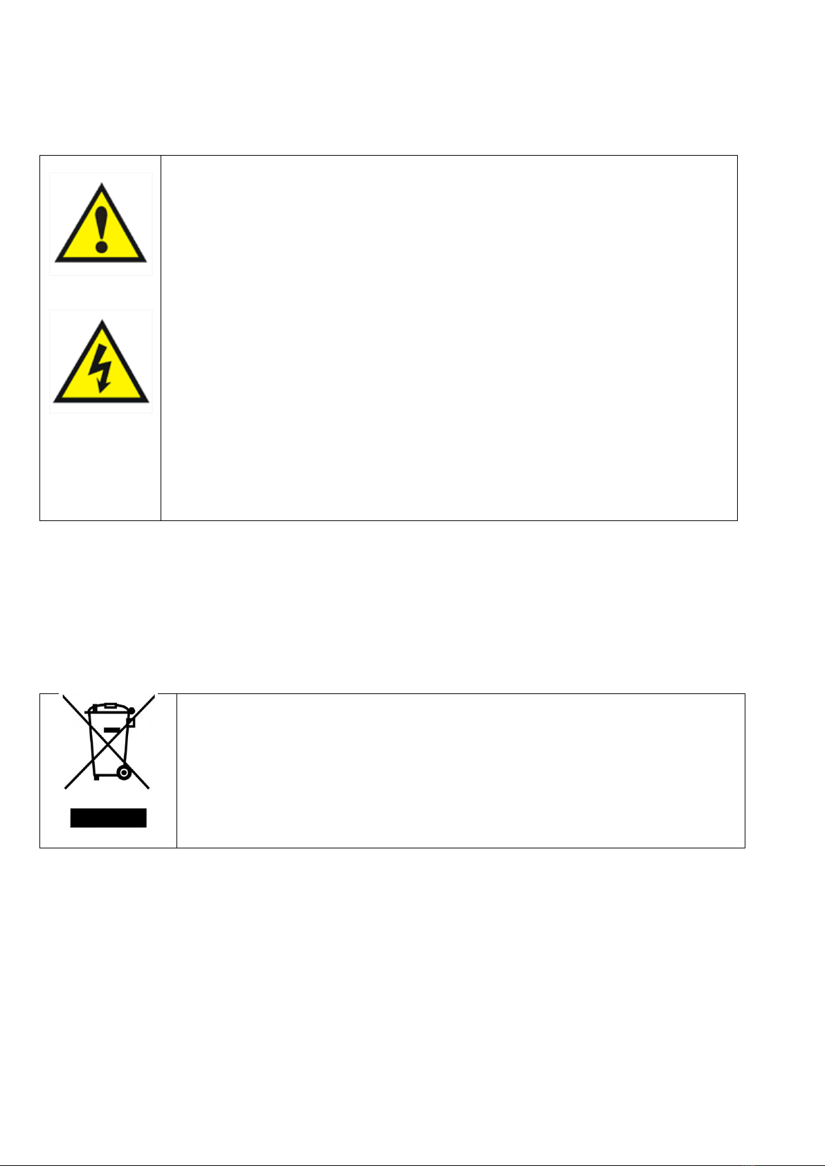
2. Safety Instructions............................................................................................................................................................. 4
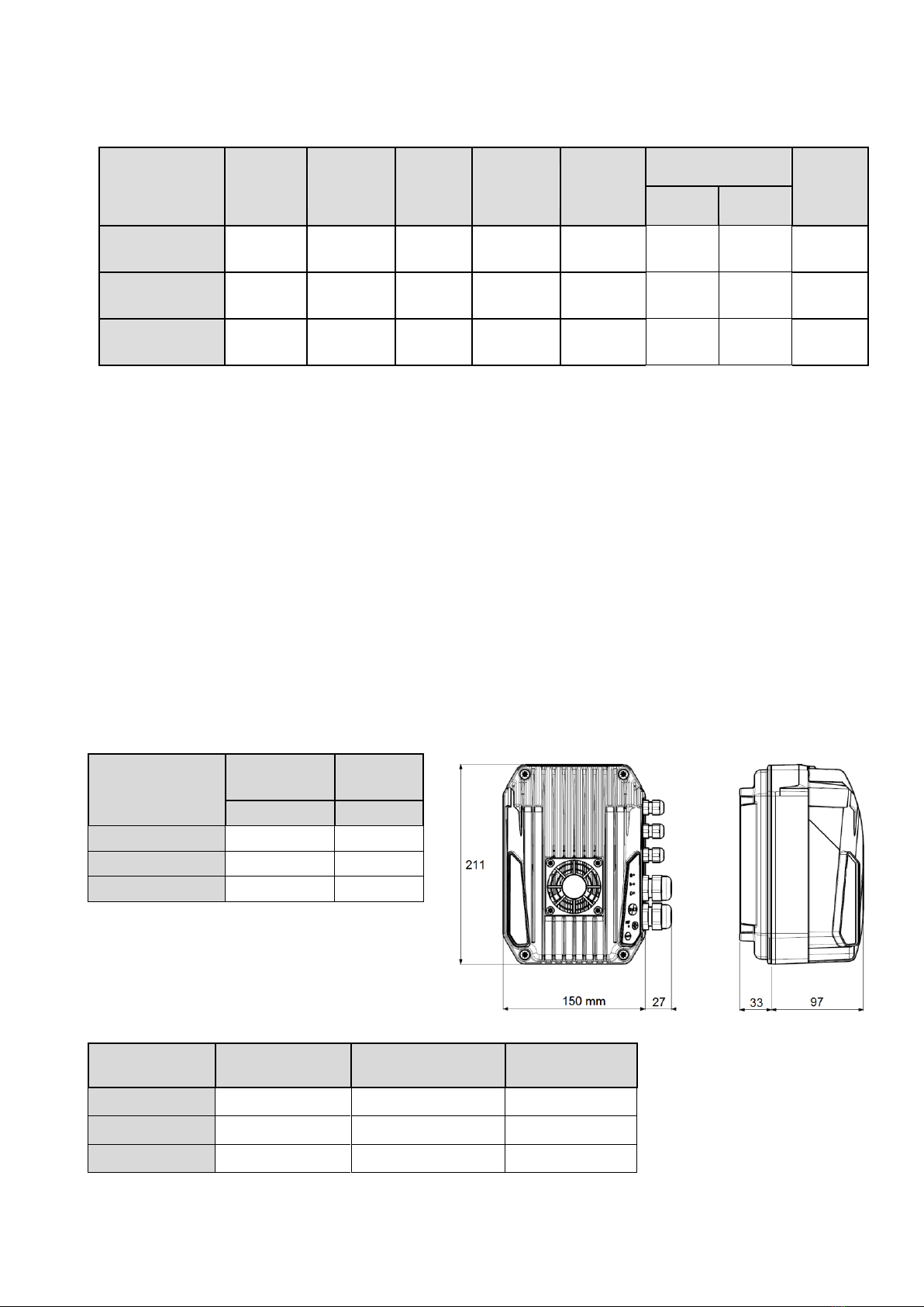
3. Technical Characteristics ................................................................................................................................................... 5
3.1 Performance ............................................................................................................................................................................ 5
3.2 Weight and dimensions .......................................................................................................................................................... 5
3.3 Cable entries ............................................................................................................................................................................ 5
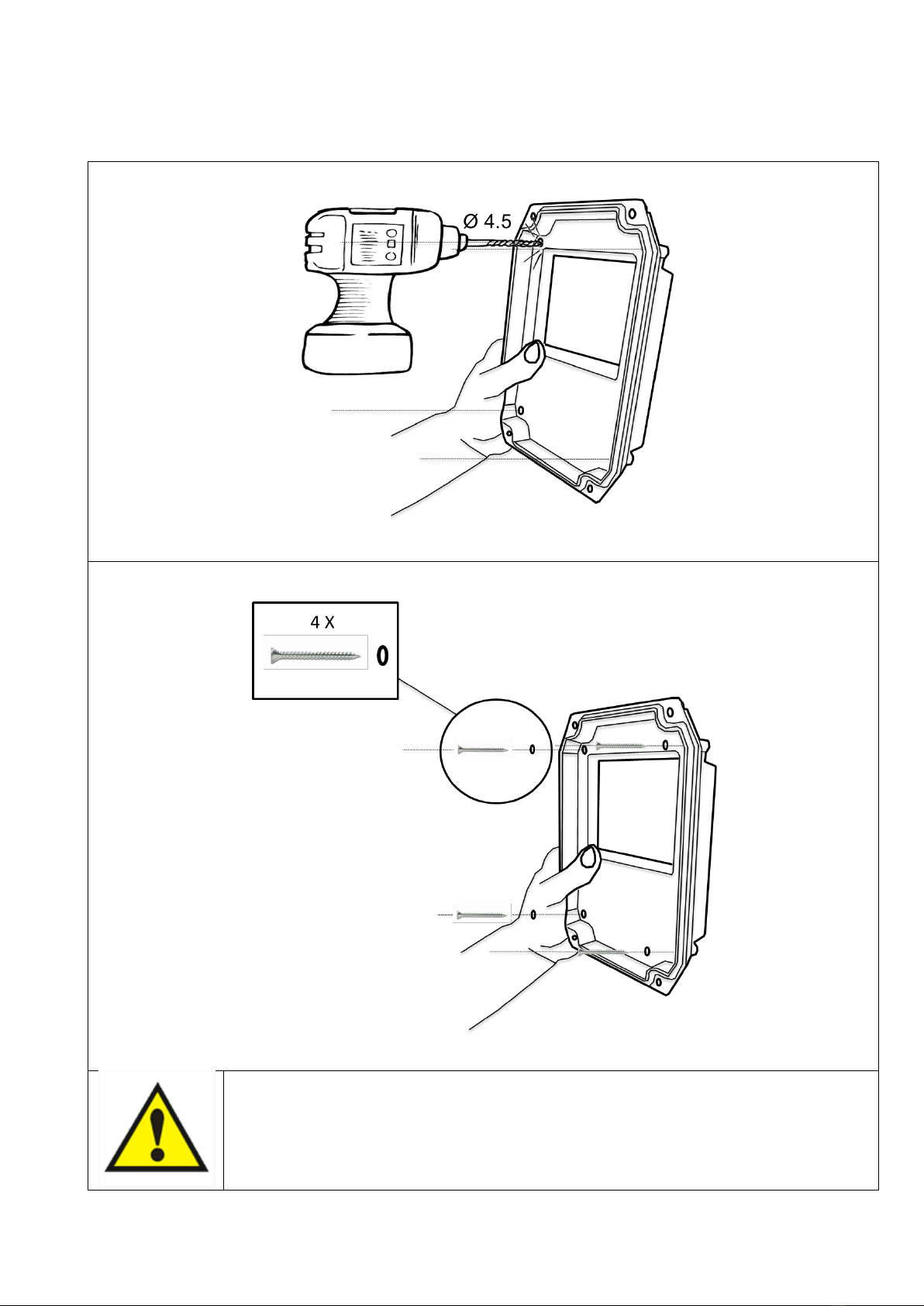
4. MIDA Solar installation...................................................................................................................................................... 6
4.1 Mechanical installation ............................................................................................................................................................ 6
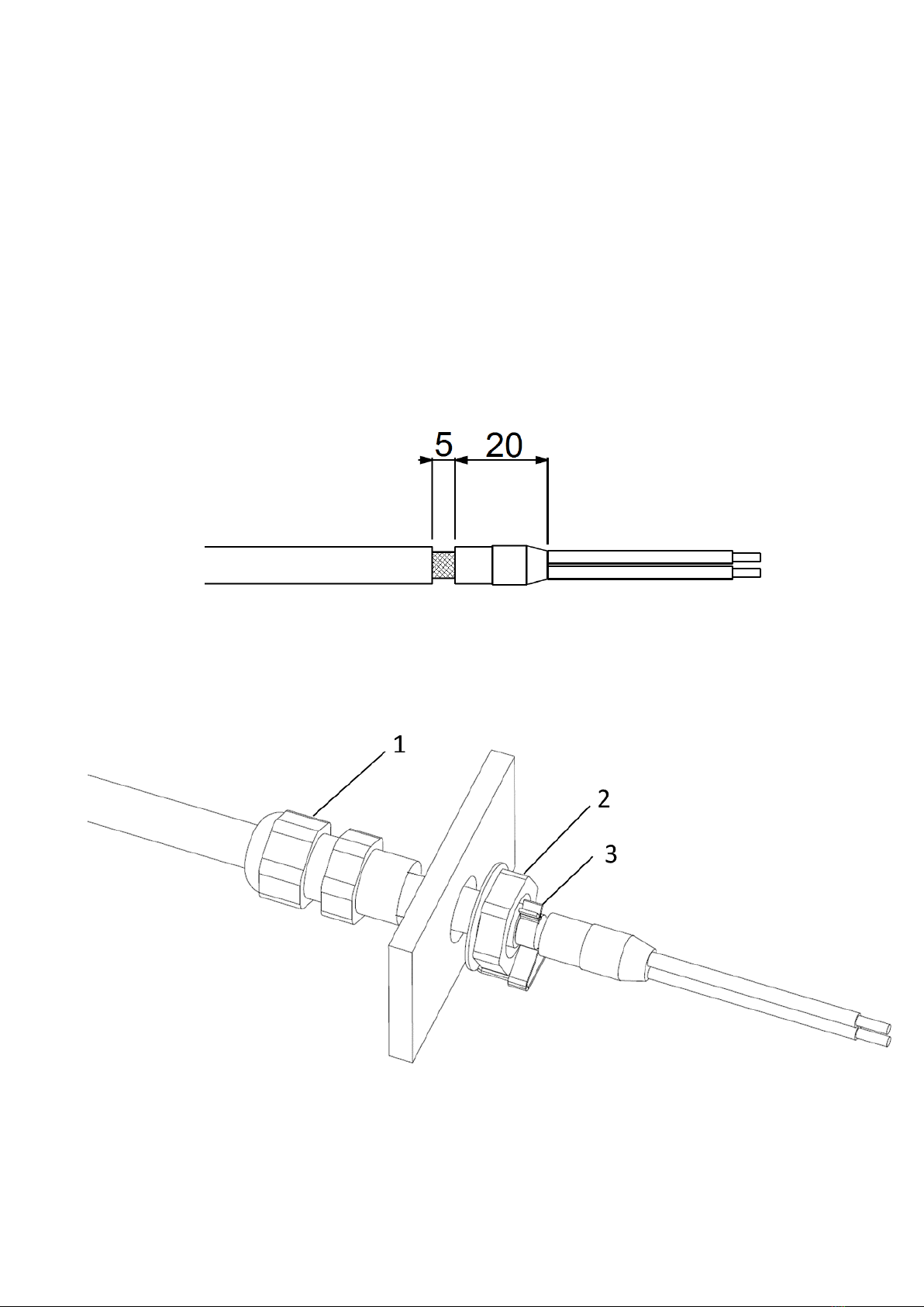
5. Electric wiring.................................................................................................................................................................... 8
5.1 Protections............................................................................................................................................................................. 11
5.2 Electromagnetic compliance.................................................................................................................................................. 11
5.3 Installation with long motor cables ....................................................................................................................................... 11
6. MIDA Solar use and programming ....................................................................................................................................12
6.1 Monitoring and programming............................................................................................................................................... 13
6.1.1 Monitoring ................................................................................................................................................................. 13
6.1.2 Programming.............................................................................................................................................................. 14
6.1.3 FOC motor control ...................................................................................................................................................... 23
7. Protections and alarms.....................................................................................................................................................25

3
1. MIDA Solar Introduction
MIDA Solar inverters come to power traditional pumping systems using photovoltaic energy.
In this way it’s possible to convert old systems in renewable energy installations or to use the same AC pumps in the creation
of independent, cost-saving and environmentally sustainable water systems.
MIDA Solar is able to convert DC voltage coming from photovoltaic panels into AC voltage for powering any pump.
MPPT (Maximum Power Point Tracking) maximizes, for various conditions of irradiation and temperature, the electrical
power drawn from the panels so the amount of pumped water.
Pump speed is constantly adapted to available solar irradiation thus maximizing the amount of pumped water and making
possible operation even in low irradiation conditions.
MIDA Solar also offers complete pump protection against over-voltage, over-current and dry running.
MIDA Solar can be used with any type of pump thus offering maximum flexibility in several application areas. In the use with
submersible pumps, MIDA Solar allows to fill tanks for watering livestock or simply irrigate lawns or crops.
In the use with surface pumps, MIDA Solar can serve an irrigation fishing from a nearby water reserve or feed with no energy
cost a pool pump.
The MP (MultiPower) versions are able to be powered also by alternating voltage (grid or generator).

4
2. Safety Instructions
The manufacturer strongly suggests carefully reading this operation manual before using and installing its products
Any operation (installation, maintenance and repair) must be carried out by trained, skilled, and qualified personnel.
Failure to observe and follow the instructions in this manual may result in dangerous and potentially lethal electric shock.
Pay attention to all standard safety and accident prevention regulations
The device must be connected to power supply via a switch to ensure the
complete disconnection from the network before any operation on the MIDA
Solar itself (including visual inspection) and/or on the connected load.
Disconnect MIDA Solar from the power supply before commencing any work.
Do not remove, for any reason, the cover and the cable plate without having first
disconnected the device from the main power supply and having waited at least
5 minutes.
MIDA Solar and pumping system must be grounded properly before operation.
For the entire period MIDA Solar is powered, high voltage is present on the
output terminals of the inverter whether or not the pump is running.
Tightening all the screws on the cover with washers is recommended before
powering the device. Otherwise, there may be a failure to connect the cover to
ground, creating the risk of electric shock or even death.
In the MultiPower (MP) models:
• Protections must be used on both the AC and DC side.
• Switching between AC and DC power supply must be done by an AC / DC switch
in accordance with local regulations.
• Connect only one power source (AC or DC) at a time.
Avoid any shock or significant impact during transport.
Check the MIDA Solar immediately upon delivery and check for damage and/or missing parts. If either occurs, immediately
notify the supplier.
Damages due to transport, incorrect installation, or improper use of the device will null and void the warranty.
Tampering or disassembly of any component will automatically void the warranty.
The manufacturer cannot be held responsible for any damages to people and/or property due to improper use of its
products.
Devices marked with this symbol cannot be disposed of in household waste but
must be disposed of at appropriate waste drop-off centres. It is recommended
to contact the Waste Electrical and Electronic Equipment drop-off centres
(WEEE) in the area. If not disposed of properly, the product can have potential
harmful effects on the environment and on human health due to certain
substances present within. Illegal or incorrect disposal of the product is subject
to serious administrative and/or criminal penalties.

5
3. Technical Characteristics
3.1 Performance
Model
V in DC
[VDC]
V in AC *
[VAC]
Max I in
[A]
Max I out
[A]
Max V out
[VAC]
Typical motor P2 **
Size
[VAC]
[kW]
MIDA Solar 203
90 - 400
90 - 265
11
3,5
250
1x230
3x230
0,37
0,55
1
MIDA Solar 205
90 - 400
90 - 265
11
5
250
1x230
3x230
0,55
1,1
1
MIDA Solar 207
90 - 400
90 - 265
11
7,5
250
1x230
3x230
0,75
1,5
1
* AC power available only for MIDA Solar MP models.
** Typical motor power. It is recommended to refer to rated motor current when selecting the MIDA Solar model.
P.F. line side (when powered with AC): 1
Power frequency: 50 - 60 Hz (+/- 2%)
Stocking temperature: -30 to 70 °C (-22 to 158 °F)
Min. ambient temperature: -10 °C (-14 °F)
Max. ambient temperature: 50°C (122 °F)
Max. altitude at rated current: 1000 m
Max relative humidity: 95% without condensation
Grade of protection: IP66 (NEMA 4X) or motor IP when connected to motor terminal box *
Connectivity: Bluetooth SMART for monitoring and programming + Modbus RTU.
* Protect the device from direct exposure to sunlight and atmospheric agents
3.2 Weight and dimensions
Model
Weight *
Size
[Kg]
MIDA Solar 203
2,5
1
MIDA Solar 205
2,5
1
MIDA Solar 207
2,5
1
* Weight without packing.
3.3 Cable entries
When MIDA Solar is coupled on motor terminal box, install the cap instead of motor cable gland.
When MIDA Solar is fixed on the wall, install the motor M20 cable gland.
Model
M20 cable gland
M12 cable gland
EMC clips
MIDA Solar 203
2
3
3
MIDA Solar 205
2
3
3
MIDA Solar 207
2
3
3
SIZE 1

6
4. MIDA Solar installation
4.1 Mechanical installation
MIDA Solar on motor
MIDA Solar can be installed directly on motor terminal box in
horizontal or vertical position.
Check with motor manufacturer if it can be operated by
inverter and verify the compatibility of MIDA Solar base with
motor terminal box (see drawing).
The rubber gasket on MIDA base grants the sealing between
MIDA Solar and motor case.
Pierce the rubber gasket only in correspondence of the 4
threaded holes on motor case.
If possible use the same screws and washers which fixed the
terminal box on motor case.
See below instruction how to mount MIDA Solar on motor.
WARNING: after installation check ground earth continuity
between motor case and MIDA Solar.
1
2
3
4

7
MIDA Solar on wall
When installed on the wall, keep the protective label on MIDA Solar base in order to grant the ingress protection.
Follow below instructions how to fix MIDA Solar base on the wall.
WARNING: use the provided O-rings with screws in order to grant IP protection

8
5. Electric wiring
MIDA Solar 203, 205, 207
Power supply
AC input (for MP models): L(L1), N(L2), P.E.
DC input: L(L1), N(L2), P.E.
With DC input it is not necessary to respect the polarity.
WARNING: In MP models, connect only one power
source (AC or DC) at a time.
It is recommended to use pre-insulated female faston terminals
6,3x0,8 mm.
In order to respect limits of EN61800-3 Category C1 for irradiated
disturbs, it is necessary to add a ferrite on input phases L and N. The
ferrite and cabling instructions are available on request.
Motor output
U, V, W, P.E.
It is recommended to use pre-insulated female
faston terminals 6,3x0,8 mm.
In case the device is mounted on motor terminal
box, it is suggested to use PVC wires 200 mm
long with cross section 1.5 mm2. In case the
device is mounted on the wall, it is
recommended using schielded cables of proper
cross section depending on cable length and
motor power. The screen has to be connected to
both side.
Recommended line cables stripping (without ferrite).
Recommended motor cables stripping.

9
Analog inputs (sensors)
AN1: 4-20 mA, sensor 1
AN2: 4-20 mA, sensor 2
AN3: 0-10 V, external set
AN4: 0-10 V, trimmer for frequency regulation or external set 2
+10
+15
It is recommended to use pre-insulated ferrules.
Use shielded signal cables by placing the screen at one end using the provided EMC clips.
Follow the below figures for correct cable stripping and EMC clip assembling.
1. M12 cable gland
2. Locknut
3. EMC clip

10
Digital inputs
•IN1 : motor start / stop
•IN2 : motor start / stop or set value 1 - 2 switching*
* only when “control mode: constant value 2 values”is selected.
It is recommended to use only volt free contacts.
Digital inputs can be configured as Normally Open or Normally Closed by software. Read programming chapter.
It is recommended to use pre-insulated ferrules.
Use shielded signal cables by placing the screen at one end using the provided EMC clips.
Digital outputs
NO1, COM1 : motor status, closed contact with motor running.
NC1, COM1: motor status, closed contact with motor stopped.
NO2, COM2: alarm status, closed contact without alarm.
NC2, COM2: alarm status, closed contact with alarm or no power supply.
Relays are volt free contacts. Max. voltage to the contacts is 250 V with max current 5 A.
It is recommended to use pre-insulated ferrules.
Use shielded signal cables by placing the screen at one end using the provided EMC clips.
COMBO serial:
S1+, S1-, G
It is recommended to respect the polarity linking more MIDA Solars in series (up to 8 units)
It is recommended to use pre-insulated ferrules.
Use shielded signal cables by placing the screen at one end using the provided EMC clips.
MODBUS RTU serial:
S2+, S2-, G
It is recommended to respect the polarity.
It is recommended to use pre-insulated ferrules.
Use shielded signal cables by placing the screen at one end using the provided EMC clips.

11
5.1 Protections
The protections required upstream each MIDA Solar depends on the type of installation, and local regulations.
Safety protections on both AC (in MP models) and DC side must be used.
For DC side we recommend to use 1000 VDC circuit breaker and, if possible, 1000 VDC surge protection.
For AC side we recommend to use overload protection with the characteristic curve of type C and type B circuit breaker,
sensitive to both AC and DC current.
5.2 Electromagnetic compliance
To ensure electromagnetic compatibility (EMC) of the system, it is necessary to apply the following measures:
Always connect the device to ground.
Use shielded signal cables by placing the screen at one end using the EMC clips.
Use motor cable as short as possible (<1 m / <3 ft). For longer lengths, it is recommended to use shielded cables
connecting the screen at both ends.
Separate signal, motor, and power supply cables.
In order to respect limits of EN61800-3 Category C1 for irradiated disturbs, it is necessary to add a ferrite on input phases L
and N. The ferrite and cabling instructions are available on request.
5.3 Installation with long motor cables
With long motor cables it’s recommended to decrease the
commutation frequency to 2.5 kHz. This reduces the
probability of voltage spikes in the motor windings which
may damage the insulation.
To prevent dangerous overheating of dV/dt and sinusoidal
filters it is recommended to set the correct PWM value in
relation to the cable length.
For motor cable lengths up to 50 meters it’s recommended
to place between MIDA Solar and motor a dV/dt reactance,
available on request.
For motor cable lengths greater than 50 meters it’s
recommended to place between MIDA Solar and motor a
sinusoidal filter, available on request.

12
6. MIDA Solar use and programming
MIDA Solar can be operated in a basic way through the included keyboard.
Stand-by red led
Red led ON: unit is powered with correct input
voltage
Blinking red led: undervoltage
Motor running
green led
Green led ON: motor is running
Green led OFF: motor is stopped
When the units is on “constant value” control mode,
the green led blinks with higher frequency as much
as the measured value is next to set value. If
measured value is the same as set value, the green
led is steady.
Alarm yellow led
Yellow led blinks with frequency which depends on
alarm type. See “Alarms” chapter.
Motor start and
stop button
Motor start and stop.
If the unit is in alarm status, it is possible to try
resetting the alarm by pressing the button two
times.
SET green led
Green led is ON when it’s possible to modify the set
value (constant value mode) or the set frequency (fix
frequency mode). Keep pressed the Up button or the
Down button more than 5 seconds in order to
enable the set adjusting.
If the SET led is off, it is not possible to change the
set value.
When two or more units are in COMBO mode, the
SET led blinks only on master unit. In this way it is
possible to understand which unit in the group is the
master and thus act on it to start and stop the
system.
Green led blinks fast when the unit is connected to
smartphone and remotely controlled by the App.
Up button
Through the UP button is possible to increase the set
value (constant value mode) or the set frequency (fix
frequency mode).
In order to allow set changing it is necessary to keep
pressed the UP button or the DOWN button more
than 5 seconds till the green SET led becomes ON.
Down button
Through the DOWN button is possible to reduce the
set value (constant value mode) or the set frequency
(fix frequency mode.
In order to allow set changing it is necessary to keep
pressed the UP button or the DOWN button more
than 5 seconds till the green SET led becomes ON.

13
6.1 Monitoring and programming
In order to access to parameters monitoring and programming it is necessary to use a smartphone or tablet with Bluetooth
4.0 (BTLE) and Nastec NOW App installed. The App is available on Android or iOS and can be downloaded free of charge
through the on-line stores.
It is possible to disable the BTLE connection by removing power supply, wait at least 30 seconds till the red STAND-BY led is
OFF, keep pressed together START/STOP button and DOWN button and give power supply. Release the buttons after 5
seconds.
It is then possible to enable the BTLE connection by removing power supply, wait at least 30 seconds till the red STAND-BY
led is OFF, keep pressed together START/STOP button and UP button and give power supply. Release the buttons after 5
seconds.
Through the App it is possible to:
Monitor multiple operating parameters simultaneously.
Get statistics of energy consumption and check alarms history.
Perform reports with the possibility to insert notes, images and email them or keep them into the digital archive.
Make programs, save them in the archive, copy them to other devices and share them among multiple users.
Remotely control, via wi-fi or GSM, a device, using a smartphone nearby as a modem.
Access to manuals and additional documentation.
Have on-line help on parameters and alarms details.
6.1.1 Monitoring
Following parameters can be monitored through the App in “Monitor” selection.
Actual value [bar]
Actual value is the value read by the sensor.
Set value [bar]
Set value is the value which has to be kept constant.
Frequency [Hz]
Motor running frequency.
Voltage Bus DC [V]
DC voltage on capacitor bus.
Motor current [A]
Phase current absorbed by the motor.
Motor power factor
Motor cosphi (P.F.).
Power [W]
Electrical power absorbed by the motor.
Module temperature [°C]
IGBT module temperature.
PCB temperature [°C]
Printed circuit board temperature.
Inverter hours [h]
Total inverter hours.
Motor hours [h]
Total motor running hours.
Address
Unit address when in COMBO mode.
ALARM HISTORY
Record of last 8 alarms.

14
6.1.2 Programming
Parameters are organized in four main menus: CONTROL, MOTOR, IN/OUT, CONNECT.
Parameters are password protected in 2 levels of access:
Installer level (CONTROL, IN/OUT). Password: 001
Advanced level (MOTOR, CONNECT). Password: 002
IN/OUT PARAMETERS
Parameter
Default
Description
bar
Unit [bar,%,ft,in,cm,m,K,F,C,gpm,l/min,m3/h,atm,psi]
16
Sensor full scale.
0
Sensor minimum value.
20%
Zero correction for analog input 1 (4-20 mA)
(20 mA x 20% = 4 mA).
20%
Zero correction for analog input 2 (4-20 mA)
(20 mA x 20% = 4 mA).
0%
Zero correction for analog input 3 (0-10V)
(10V x 00% = 0 V).
0%
Zero correction for analog input 4 (0-10V)
(10V x 00% = 0 V).
Independent
Function logic for analog input AN1,AN2 (independent, lower value,
higher value, difference 1-2).
N.O.
By selecting N.O. (normally open) MIDA Solar runs the motor if the
digital input 1 is open; motor will be stopped if the digital input 1 is
closed.
By selecting N.C. (normally closed) MIDA Solar runs the motor if the
digital input 1 is closed; motor will be stopped if the digital input 1 is
opened.
N.O.
By selecting N.O. (normally open) MIDA Solar runs the motor if the
digital input 2 is open; motor will be stopped if the digital input 2 is
closed.
Unit
XXXXX
F. scale sensor
XXX.X
Min.value sensor
XXX.X
Offset input 1
[%]
Offset input 2
[%]
Offset input 3
[%]
Offset input 4
[%]
AN1,AN2 function
XXXXXX
Digital input 1
N.O. / N.C.
Digital input 2
N.O. / N.C.

15
Parameter
Default
Description
By selecting N.C. (normally closed) MIDA Solar runs the motor if the
digital input 2 is closed; motor will be stopped if the digital input 2 is
opened.
Disable
Enabling or disabling digital input 1 manual reset.
Disable
Enabling or disabling digital input 2 manual reset.
3
Digital input IN2 delay.
Digital input IN1 has 1 second fix delay.
CONTROL PARAMETERS
Parameter
Default
Description
MPPT
Constant value
Fix speed
Const.value 2 set
Fix speed 2 val.
External speed
MPPT
Mode of control:
MPPT: pump speed is adjusted in order to obtain maximum power
available from PV panels.
Constant value: MIDA Solar changes the pump speed to keep the
set value constant regardless water demand.
Fix speed: MIDA Solar feeds the pump at set frequency, so the
pump speed is kept constant.
Const. value 2 set: the two values are selected by opening or closing
the digital input IN2.
Fix speed 2 val: the two valus are selected by opening or closing the
digital input IN2.
External speed: control motor frequency by using analogical input
AN4.
10
Maximum value allowed in the
system. If the readen value goes over
this value, an alarm occurs and the
pump is stopped. Pump is
automatically restarted if the readen
value goes below the maximum value
for a period of at least 5 seconds.
0
Minimum value allowed in the
system. If the readen value goes
lower than this value, an alarm occurs
and the pump is stopped. Pump is
automatically restarted if the readen
value goes higher than the minimum
value for a period of at least 5
seconds.
Dig. input 1 manual reset
Enable / Disable
Dig. input 2 manual reset
Enable / Disable
Dig.In.2 delay
[s]
Control mode
MPPT
Constant value
Fix speed
Const.value 2set
Fix speed 2 val.
External speed
Max alarm value
XXX.X [bar]
Min alarm value
XXX.X [bar]

16
Parameter
Default
Description
MPPT
Constant value
Fix speed
Const.value 2 set
Fix speed 2 val.
External speed
OFF
Enabling of set value changing by
analog input AN3.
3
Set value to be kept constant.
0
Value compensation at the maximum
frequency for each pump. Acting on
the green button you can reverse the
sign.
3
Set value to be kept constant.
0
Value compensation at the maximum
frequency for each pump. Acting on
the green button you can reverse the
sign.
5
Time to update set value for
compensation.
Ext.set enabling
ON/OFF
Set value
XXX.X [bar]
Compensation
XXX.X [bar]
Set value 2
XXX.X [bar]
Compensation 2
XXX.X [bar]
Set value update
XX [s]

17
Parameter
Default
Description
MPPT
Constant value
Fix speed
Const.value 2 set
Fix speed 2 val.
External speed
To ensure proper operation of pressure control is recommended to place the sensor near the pump.
To compensate the pressure loss in the pipes (proportional to flow) it is possible to vary the pressure set in a linear
relation with respect to frequency.
It can perform the following test to verify the correct value of compensation:
1. install a pressure gauge away from the pressure sensor
2. open completely the valve
3. check the pressure gauge
--> Set the value of compensation. equal to the difference of the values from the two gauges.
When using a group of pumps, the pressure compensation to be applied to each pump is equal to the total pressure
compensation (when all the pumps are running at full speed) divided by the number of pumps in the group.
50
Frequency value to feed the pump.
50
Frequency value to feed the pump.
50
Minimum frequency below which the
pump tries to stop.
5
Delay for which the pump tries to
stop below freq.min.control.
20
Ramp time from freq.min.control to
min.motor freq. If, during this time,
the read value goes below the (set
value - delta control), MIDA Solar
Q
H
Minmot. freq. Max mot. freq.
Set value (3 bar)
4 bar
Pressure
sensor
300 m
Compensation (1 bar)
Operating freq.
XXX [Hz]
Operating freq. 2
XXX [Hz]
Freq.min.control
XXX [Hz]
Stop delay
XX [s]
Control ramp
XXX.X [s]

18
Parameter
Default
Description
MPPT
Constant value
Fix speed
Const.value 2 set
Fix speed 2 val.
External speed
powers the motor again; otherwise,
MIDA Solar will stop the pump.
0.1
Value drop below the set value
required to restart the pump during
control ramp.
0.5
Value drop below the set value
required to start the pump from stop
condition.
0.5
Value increase respect to set value
which must be passed so that there is
a forced shutdown of the pump.
XXX
Open circuit voltage of PV strings.
Please refer to PV panels datasheet.
XX
MPPT voltage gap.
XX
MPPT time gap.
XX
MPPT frequency gap.
sec
Hz
Freq.min.control
press.
Set value
Minmot. freq
Stop delay Control ramp
Delta control
Delta control
XXX.X [bar]
Delta start
XXX.X [bar]
Delta stop
XXX.X [bar]
Open circuit Volt. PV
V = XXX [V]
MPPT: volt. gap
dV = XX.X [V]
MPPT: time gap
dt = XX.X [s]
MPPT: freq. gap
df = XX.X [Hz]

19
Parameter
Default
Description
MPPT
Constant value
Fix speed
Const.value 2 set
Fix speed 2 val.
External speed
Kp and Ki parameters allow the
dynamic control of system by MIDA
Solar; set values (Ki=50, Kp=005) are
usually enough to get a valid dynamic
control.
OFF
Enabling or disabling COMBO
operation as described in COMBO
chapter.
00
MIDA Solar address:
00 master
01 to 07 slaves
OFF
Function to allow alternating
between the MIDA Solars connected
in COMBO in order to allow equal use
of each pump in the group; master
will reorganize the starting priority of
the pumps by checking the life of
each of them.
0
Maximum difference in terms of
hours between MIDA Solars in the
group.
0 stays for 5 minutes.
OFF
With this parameter it is possible to
activate the synchronous operation
(same speed) of the pumps in
COMBO.
It is however necessary to
appropriately lower the parameter
"f. min. control".
0
Delay time with which the slaves start
after the variable speed pump has
reached the maximum frequency and
the pressure value has fallen below
set value –delta control
Direct
Direct: increasing motor speed also
misured value increases
Reverse: increasing motor speed,
misured value decreases.
0
Pump periodic autorun after XX hours
of inactivity. Value 0 makes function
disabled.
Warning, review the advice in chapter
1.
0.65
Cosphi value below which the unit
stops the motor and give “no water”
alarm.
Kp
Ki
COMBO
ON/OFF
Address
XX
Alternance
ON/OFF
Alternance period
XX [h]
COMBO synchrony
ON/OFF
Start delay AUX
t = XX [s]
PI control
Direct/Reverse
Periodic autorun
t = XX [h]
Dry run cosphi
X.XX

20
Parameter
Default
Description
MPPT
Constant value
Fix speed
Const.value 2 set
Fix speed 2 val.
External speed
10
Restart delay after a dry running
alarm. At each tentative (max 5)
restart delay will be doubled.
MOTOR PARAMETERS
Parameters
Default
Description
Three
phase
Threephase asynchronous
Synchronous PM
Singlephase
Scalar V/f
XXX
Motor rated voltage (as shown on motor nameplate).
0%
Voltage increase during the motor start up.
Warning: An excessive value can seriously damage the motor. Contact the
motor manufacturer for further information.
XX
Rated motor current as per its nameplate indication increased by 5%.
50
Rated motor frequency as per its nameplate.
50
Maximum motor frequency. Note: by reducing the maximum motor
frequency, maximum current will be reduced as well.
20
Minimum motor frequency.
4
Ramp-up time to reach the speed required to achieve the set pressure (or
frequency value). Longer times delay the system reaching the preset value
but better protect system components.
Excessively long ramp-up times can create difficulties in MIDA Solar setup,
and can also cause false overload alarms.
4
Ramp-down time to reach zero speed. Longer times keep the system
pressurized, while protecting the system components.
Excessively long ramp-down times can create difficulties in MIDA Solar
setup. Excessively short ramp-down times can cause false overload alarms.
Restarts delay
XX [min]
Motor type
XXXXXX
Rated motor Volt.
XXX [V]
Voltage boost
XX.X [%]
Rated motor Amp.
XX.X [A]
Rated motor freq
XXX [Hz]
Max motor freq.
XXX [Hz]
Min motor freq.
XXX [Hz]
Ramp up time
XXX.X [sec]
Ramp down time
XXX.X [sec]
This manual suits for next models
2
Table of contents
Other Nastec Inverter manuals
Popular Inverter manuals by other brands

Hakko Electric Machine Works Co., Ltd.
Hakko Electric Machine Works Co., Ltd. HAP2031 Handling manual

Gyrus Acmi
Gyrus Acmi PlasmaKinetic user manual

SSD Drives
SSD Drives 650V quick start

Senci
Senci SC4000i user guide

LG
LG LG A1C-V5 Series installation manual

SMA
SMA Sunny Island 5048 Technical description manual