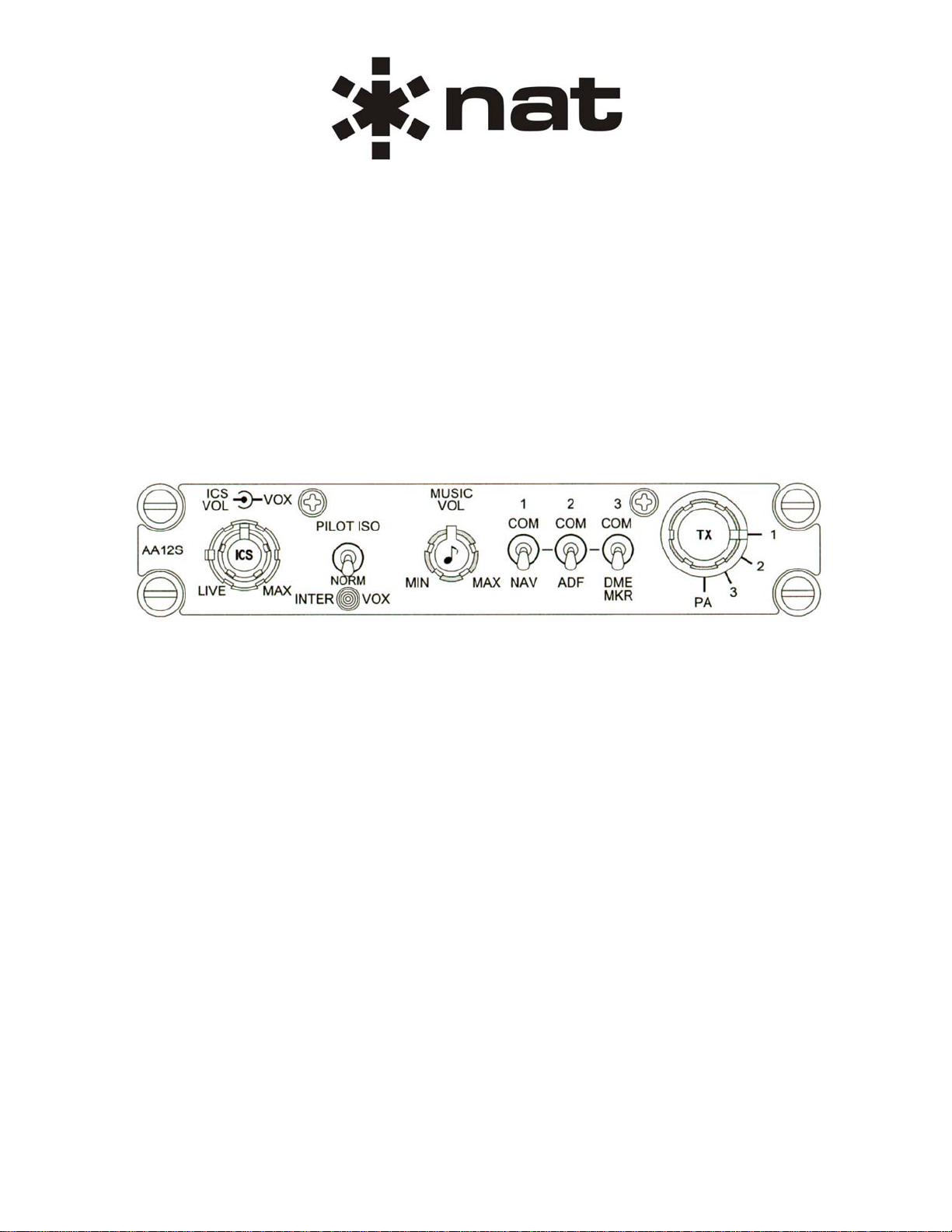
AA12S Series Compact Audio Controller
SM69 Installation and Operation Manual
Section 2 Rev: 1.00 Issue 4 Page 2-2
ENG-FORM: 805-0117.DOT
CONFIDENTIAL AND PROPRIETARY TO NORTHERN AIRBORNE TECHNOLOGY LTD.
2.4 Installation Procedures
2.4.1 Warnings
WARNING:
High volume settings can cause hearing damage.
Set the headset volume control to the minimum volume setting prior to
conducting tests, and slowly increase the headset volume to a
comfortable listening level.
2.4.2 Cautions
CAUTION:
The shielding and routing of the MIC and ICS TIE LINES used in the AA12S
installation is very critical and poor performance of the aircraft audio system will
result if these issues are not handled properly.
The operation of the VOX intercom can be severely degraded by the quality and
type or mix of microphones used in the aircraft. If one user has a 'hot'
microphone, it will increase the electrical signal to the VOX circuit and the VOX
SQUELCH will have to be set to quiet this microphone. The other microphones
may not be able to generate enough electrical energy to overcome this VOX
SQUELCH setting, and will break up or not be heard at all.
2.4.3 Cabling and Wiring
All wire shall be selected in accordance with the original aircraft manufacturer's Maintenance Instructions
or AC43.13-1B Change 1, Paragraphs 11-76 through 11-78. Unshielded wire types shall qualify to
MIL-W-22759 as specified in AC43.13-1B Change 1, Paragraphs 11-85, 11-86, and listed in Table 11-11.
For shielded wire applications, use Tefzel MIL-C-27500 shielded wire with solder sleeves (for shield
terminations) to make the most compact and easily terminated interconnect. Follow the connector map in
Section 2.7 as required.
Coaxial cable shall be selected in accordance with MIL-C-17 unless otherwise specified. Do not use coax
cable with PVC insulation. Teflon dielectric cable is encouraged at or above VHF frequencies or where
cable runs exceed 8 feet. Note that at VHF frequencies, cables losses due to long cable runs and tight
bends may reduce the ERP (Effective Radiated Power) by greater than 50%.
Allow 3" from the end of the shielded wiring to the shield termination to allow the connector hood to be
easily installed. Reference the interconnect drawing in Section 2.7 for shield termination details. Note that
the hood is a "clamshell" hood, and is installed after the wiring is complete. Aircraft harnessing shall
permit the unit to be removed from the panel for easy access to all side adjustments. Do NOT mount the
unit until all adjustments have been performed.
Maintain wire segregation and route wiring in accordance with the original aircraft manufacturers
Maintenance Instructions. Coaxial cables shall be routed separately from existing wire bundles in the
aircraft to minimize electromagnetic coupling effects.