National Comfort Products CPG41228-U User manual

25
Installation Guide for Comfort Pack (CPG) Units
The indoor blower motor and the outdoor fan motor have
permanently lubricated bearings and do not require routine
service. The refrigeration system is sealed and factory charged
with R-410A so that routine maintenance is not required.
Cleaning of the outdoor coil, indoor coil, drain pan, and inside
the bottom of the chassis are recommended at least once a
year, and more often if the equipment is operated in a dusty
or hostile environment. The electrical controls do not require
routine service.
Power to the unit should always be turned off before performing
service or removing the cooling chassis from the unit.One
power connector and one control circuit connector are provided
for easy disconnecting and re-connecting of the wires between
the cooling chassis and cabinet. The controls enclosure cover
must be removed to allow access to the screws holding the
indoor blower cover plate to the cooling chassis and cabinet.
After reinstalling the cooling chassis, the indoor blower cover
plate and controls enclosure cover must be reinstalled.
IF YOU TURN OFF POWER SUPPLY, TURN OFF
THE GAS. SEE HAZARD LEVELS, PAGE 3. THE
MATERIAL CONTAINED IN THE MAINTENANCE
AND SERVICE SECTION OF THIS MANUAL
IS DESIGNED TO AID A QUALIFIED SERVICE
PERSON IN MAINTAINING AND SERVICING
THIS EQUIPMENT. THIS UNIT WILL OPERATE
WITH MINIMUM MAINTENANCE. TO
ENSURE LONG LIFE AND SATISFACTORY
PERFORMANCE, A HEATER THAT IS
OPERATED UNDER NORMAL CONDITIONS
SHOULD BE INSPECTED AND CLEANED AT
THE START OF EACH HEATING SEASON.
IF THE HEATER IS OPERATING IN AN AREA
WHERE AN UNUSUAL AMOUNT OF DUST,
SOOT OR OTHER IMPURITIES ARE PRESENT
IN THE AIR, MORE FREQUENT MAINTENANCE
IS RECOMMENDED. WHEN ANY SERVICE IS
COMPLETE, BE CAREFUL TO REASSEMBLE
CORRECTLY TO ENSURE THAT NO UNSAFE
CONDITIONS ARE CREATED. WHEN RE-
LIGHTING, ALWAYS FOLLOW THE LIGHTING
INSTRUCTIONS ON THE HEATER.
!WARNING
Maintenance Schedule
At least every six weeks check the filter. Clean or replace as
necessary. A clean filter in addition to providing a comfortable
environment ensures fuel-efficient operation and long heat
exchanger life. Do the following procedures at least annually.
• Clean all dirt, lint, and grease from the combustion air openings
and venter motor.
• Inspect the heat exchanger. Clean if needed.
• Check the burner for scale, dust, or lint accumulation. Clean if
needed.
• Check the vent system for soundness. Replace any parts that
do not appear sound.
• Check the wiring for any damaged wire. Replace damaged
wiring.
NOTE: USE ONLY FACTORY-AUTHORIZED
REPLACEMENT PARTS.
Burner/Control Compartment
Heat Section Burner/Control Compartment
Showing Locations of Burner Assembly and Controls
NOTE: Unit side panel is removed for clarity; side panel is not
removable. Access to the burner/control compartment is through
the small rear access panel as illustrated below.
Figure 5
Burner Assembly
Burner
Gas Valve
Venter Motor
Pressure Switch
DSI Integrated
Control Module

26
Installation Guide for Comfort Pack (CPG) Units
Inspect the Heat Exchanger
Remove the heat furnace baffle panel (see page 29). Remove any
dirt or dust accumulation. Visually check the heat exchanger for
cracks and holes. If a crack or hole is observed, replace the heat
exchanger. Thorough inspection of the heat exchanger can be
done with furnace slid out of the cabinet. (See pages 29 & 30)
Burner Service
Inspect the burner/control compartment annually to determine
if cleaning is necessary. Open the burner/control compartment
and on the burner housing, clean the compartment and follow
the instructions below to remove and clean the burner.
Instructions for Burner Removal
Note: Components may be more easily accessed with the
furnace removed from cabinet. (See page 29 & 30)
1. Shut the gas supply off ahead of the combustion valve.
2. Turn off electric supply.
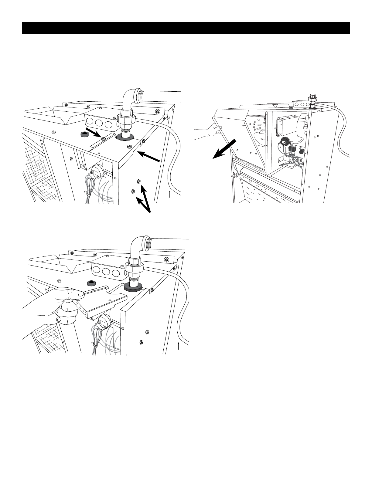
3. Remove the upper cabinet panel to expose the heat exchanger
section and the burner/control compartment (see Figure 2).
4. Carefully loosen and remove the gas valve and gas train from
the side panel and burner orifice bracket.
5. Mark and disconnect the pressure switch wires. Disconnect
the tubing and remove the pressure switch.
6. Locate the secondary air shield end cap. Remove the four
screws holding it to the air shield and remove the end cap.
7. Locate the upper burner brackets (one on each side). Remove
the two screws (one on each side) that attach the burner
assembly to the secondary air shield assembly.
8. Tilt the burner assembly slightly and lift it free from the
retaining track under the burner assembly. Remove the burner
assembly from the cabinet.
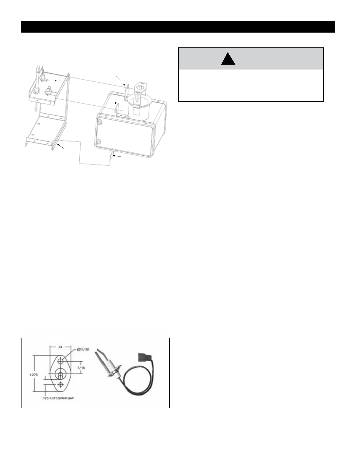
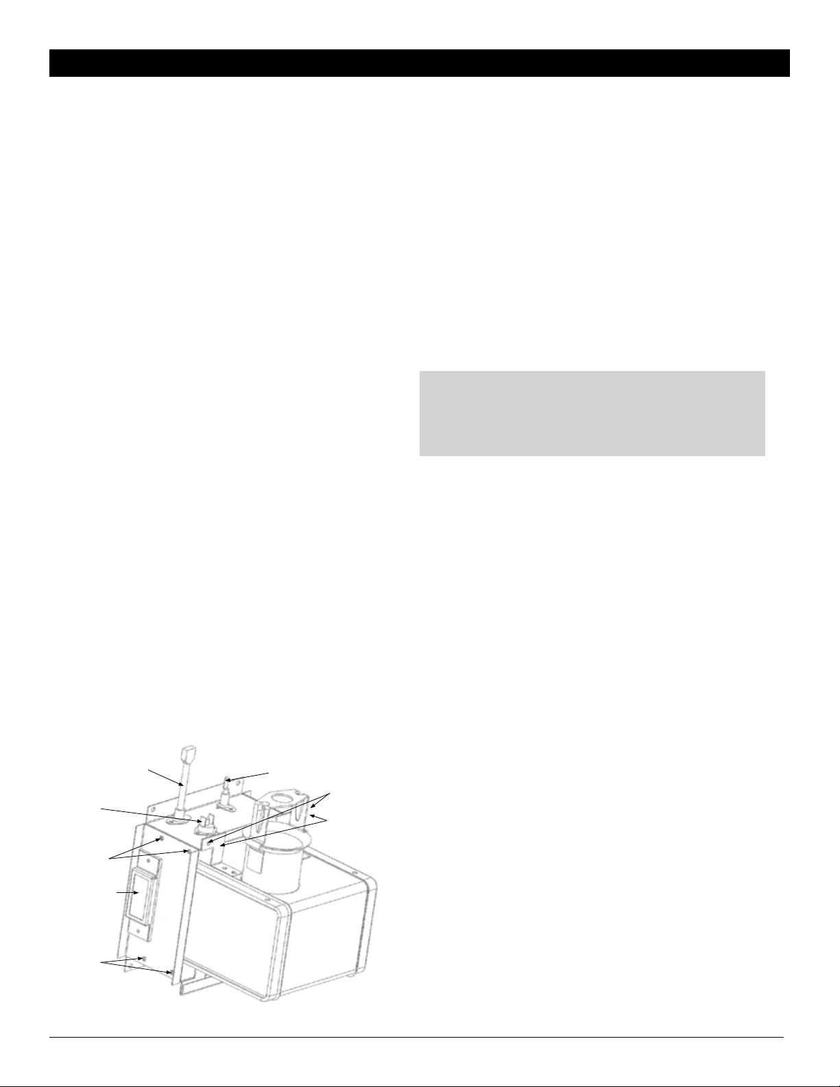
Figure 6A
Flame Rollout Switch
Ignitor
Remove screws
Sight Glass for
Flame and Ignitor
Secondary Air
Shield Assembly
Remove screws
Flame Sensor
Upper Burner Bracket
(one on each end) -
Loosen burner assembly by
removing only the two screws
indicated.
Burner Assembly
Secondary Air
Shield End Cap
Remove secondary air shield end cap
by removing four screws indicated.
Remove screw
(one on each end)
Inspect and Clean the Burner
With the burner assembly removed, shine a flashlight on the
burner ribbons. Look for carbon buildup, scale, dust, lint, and/
or anything that might restrict flow through the spaces between
the burner ribbons. Holding the burner assembly so that any
foreign material will fall away from the burner, use a stiff bristle
brush to loosen and remove any foreign material(s). If the burner
is excessively dirty, refer to Figure 6A and remove one of the
burner end caps. Remove the four screws that hold the end cap
to the burner housing. Lightly tap the end cap to remove it.
Clean all foreign material from the burner and venturi. After the
burner is thoroughly clean, replace the end cap making certain
that it is tight against the burner housing.
NOTE: IF ANY OF THE BURNER COMPONENTS
ARE DAMAGED OR DETERIORATED, REPLACE
THE BURNER ASSEMBLY.
Inspect the Lower Portion of the Heat Exchanger (with burner
assembly removed)
At the burner flame entrance of each tube, shine a bright light
into each heat exchanger section. If any light is observed,
replace the heat exchanger.
Instructions for Burner Installation
1. With lower burner brackets going inside the retaining track,
set the fully assembled, clean burner in the unit.
2. Secure the upper burner brackets to the secondary air shield
assembly.
3. Replace the secondary air shield end cap.
4. Attach and reconnect the pressure switch.
5. Reinstall the gas train and gas valve to the burner orifice
bracket and side panel.
6. Turn on the electric and the gas. Operate the furnace. Check
gas supply lines with a liquid leak detector or soap solution.
After it has been determined that there are no gas leaks and
the burner is operating satisfactorily, replace the cabinet panel
and the burner/control compartment panel.

27
Installation Guide for Comfort Pack (CPG) Units
Figure 6B
Secondary Air Shield Assembly
w/ End Cap Removed
Upper Burner Brackets
Burner Assembly
Retaining Track
Lower Burner Bracket
(one on each end) -
Place in the retaining track on the
secondary air shield assembly.
Burner Orice
Burner orifice only needs to be replaced when a change in
gas is made. When ordering a replacement orifice, give BTUH
content and specific gravity of gas, as well as the model and
serial number of the unit. To prevent dropping the orifice into
the burner housing, block the venturi with something the size of
a credit card when removing the burner orifice. Be careful not to
damage the venturi tube and/or the bracket.
Ignition System
Igniter - Refer to Figure 6A and locate the igniter. Disconnect
the wire; remove the screw and the igniter. Clean the igniter
assembly with an emery cloth. Spark gap must be maintained to
1/8" (See Figure 7) below.
Flame Sensor - Refer to Figure 6A and locate the flame sensor.
Disconnect the wire; remove the screw and the flame sensor.
Clean with an emery cloth.
Figure 7
DUE TO HIGH VOLTAGE ON THE SPARK WIRE
AND ELECTRODE, DO NOT TOUCH WHEN
ENERGIZED. SEE HAZARD LEVELS, PAGE 5.
!CAUTION
DSI Integrated Control Module - The module monitors the
operation of the heater including ignition. The only replaceable
component is the 3 amp fuse. If the fuse is blown, the problem is
most likely an external overload. Correct the problem and replace
the fuse. Do not attempt to disassemble the control module.
However, each heating season check the lead wires for insulation
deterioration and good connections.
Proper operation of the direct spark ignition system requires
a minimum flame signal of 1.0 microamps as measured by a
microammeter.
For further information and check out procedure on the direct
spark ignition system, refer to the circuit board manufacturer’s
instructions supplied with the heater.
Venter Motor and Wheel Assembly
Remove dirt and grease from the motor casing. Venter motor
bearings are permanently lubricated. The DSI Integrated Control
Module controls and monitors operation of the venter motor. If
the contacts fail to close the venter motor will not run. If the
contacts fail to open, the venter motor will not shut off, preventing
the combustion air pressure switch from opening.
Follow these instructions for replacement of the venter motor
and wheel assembly. Keep all hardware removed to be used in
reassembling and installing the replacement parts.
1. Turn off the gas and disconnect the electric power.
2. Open the burner/control compartment access panel.
3. Disconnect the three venter motor wires at their terminal block
connections.
4. Holding the motor, remove the three screws that attach the
venter motor mounting plate to the venter housing. Remove
the motor and wheel assembly from the heater.
5. Re-assemble with the replacement venter motor and wheel
assembly.
6. Follow the wiring diagram to connect the venter wires.
7. Restore power to the heater and turn on the gas. Light,
following the instructions plate. Check for proper operation.
Replace the access panel.

28
Installation Guide for Comfort Pack (CPG) Units
Limit Control
If it is determined that a limit control needs replacing, use only
the factory-authorized replacement part that is designed for
the size of heater. The limit control is accessible in the control
compartment. For approximate limit control location (see
Figure 1).
Gas Valve
The gas valve requires no field maintenance except careful
removal of external dirt accumulation and checking of wiring
connections. Instructions for testing pressure settings are in
paragraph entitled “Gas Piping and Pressures.
THE OPERATING VALVE IS THE PRIMARY
SAFETY SHUTOFF. ALL GAS SUPPLY
LINES MUST BE FREE OF DIRT OR SCALE
BEFORE CONNECTING TO THE UNIT TO
ENSURE POSITIVE CLOSURES. SEE HAZARD
INTENSITY LEVELS, PAGE 3.
!CAUTION
Pressure Switch
If it is determined that the pressure switch needs replacing, use
only the factory-authorized replacement part that is designed for
this heater. For approximate location (see Figure 5).
NOTE: A unit operating above 6000 ft elevation
requires a high altitude pressure switch, P/N
14208325 (see page 17).
Flame Rollout Switch
For approximate location (see Figure 6A). The cause of a flame
rollout switch activating must be determined. Activation of the
manually reset flame rollout switch could be caused by one or
more of the following: • Restricted or plugged heat exchanger. •
Pressurization of the heat exchanger. • Restricted combustion air
inlet or exhaust outlet in combination with a defective pressure
switch. • Electrical power interruption during operation. If a flame
rollout switch trips, inspect the burner/control compartment for
signs of excessive heat and burned wiring.
If the compartment appears normal, reset by depressing the red
button on the switch. 15 to 20 minutes are required for the switch
to cool sufficiently for resetting. A distinct click will be felt when
the switch resets. Operate the furnace. If the flame rollout switch
trips again, determine and correct the cause before resetting the
switch.
If there is damage to the burner/control compartment, repairs
must be made before resetting the switch.
If it is determined that the flame rollout switch needs replacing,
use only the factory-authorized replacement part that is designed
for that size of heater.
Vent System
Check at least once a year. Inspect all joints and seams. Replace
any defective parts.
Troubleshooting
Check the DSI Integrated Control Module (Circuit Board) - The
Integrated Circuit Board monitors the operation of the heater
and includes an LED signal that indicates normal operation
and various abnormal conditions. If the heater fails to operate
properly, check this signal to determine the cause and/or to
eliminate certain causes.
Do not attempt to repair the DSI integrated control
module; the only eld replaceable component is the
fuse.
CONTROL
STATUS GREEN LED
STEADY ON
FAST FLASH
1 FLASH
2 FLASH
3 FLASH
4 FLASH
STEADY OFF
Normal operation, no call for heat
Normal operation, call for heat
In lockout from failed ignition or flame loss
Pressure switch does not close for 30 seconds
Limit switch or rollout switch open
Limit switch is closed before venter is energized
Internal control fault or no power
FLAME
STATUS YELLOW LED
STEADY ON
SLOW FLASH
FAST FLASH
Flame sensed
Weak flame (current below 1.0 microamps = +/-50%)
Undesired flame (valve open and no call for heat)

29
Installation Guide for Comfort Pack (CPG) Units
Directions to Slide Out the Furnace
(After removing front panels)
1. Remove the (4) screws indicated at the right
Gas Line
Power
Cord
2. Remove the patch plate
Gas Line
Power
Cord
Front
Furnace
Bafe
3. Remove (2) right side screws and remove the front
furnace baffle.

30
Installation Guide for Comfort Pack (CPG) Units
5. Grasp the vertical heat
exchanger “partition”
firmly with your left hand.
Be careful not to tear the side and
bottom insulation when pulling the
heat exchanger/furnace assembly
forward.
4. Unplug (2) molex plugs before
sliding out the heat exchanger/
furnace assembly.
Lift
Pull
Forward
Power
Cord
6. With your right hand reach under the
burner box and lift the drain pan to release
the drain plug. Then lift up and pull the
assembly forward to slide out the heat
exchanger/furnace assembly.

31
Installation Guide for Comfort Pack (CPG) Units
Optional Accessories
CPWSA Wall Sleeve Adapter (Unassembled) AOmit Stamped Grilles
CPLG Architectural Louver Grille BSlotted Filter Door
CPLG-S Architectural Louver Grille for Sleeve CCombination of both A & B
CPLG-P Architectural Louver Grille Painted 14208343 LP Kit (38 MBTU)
CPLG-SP Architectural Louver Grille for Sleeve Painted 14208344 LP Kit (51 MBTU)
CPSG-P Stamped Grille Painted 14208345 LP Kit (64 MBTU)
Performance Data - All Units 9.2 EER and 80% Thermal Efciency with 409 SS.HX
Models Nominal
Cooling Tons Cooling BTU EER Heating BTU Input Heating BTU Output Shipping
Weight
CPG41228-U 1 12,000 9.2 28,000 22,400 315
CPG41238-U 1 12,000 9.2 38,000 30,400 315
CPG41828-U 1.5 18,000 9.2 28,000 22,400 325
CPG41838-U 1.5 18,000 9.2 38,000 30,400 325
CPG41851-U 1.5 18,000 9.2 51,000 40,800 325
CPG41864-U 1.5 18,000 9.2 64,000 51,200 325
CPG42428-U 2 22,400 9.2 28,000 22,400 350
CPG42438-U 2 22,400 9.2 38,000 30,400 350
CPG42451-U 2 22,400 9.2 51,000 40,800 350
CPG42464-U 2 22,400 9.2 64,000 51,200 350
CPG43028-U 2.5 27,000 9.2 28,000 22,400 360
CPG43038-U 2.5 27,000 9.2 38,000 30,400 360
CPG43051-U 2.5 27,000 9.2 51,000 40,800 360
CPG43064-U 2.5 27,000 9.2 64,000 51,200 360
Electrical Data
Models Voltage Compressor Outdoor Fan Motor Indoor Blower
Motor
Total
Amps
Minimum
Circuit
Amps
Maximum
Overcurrent
Protector
RLA LRA HP FLA LRA HP FLA
CPG41228-U 208-230/60/1 5.1 29.5 1/4 1.8 3.6 1/3 3.0 9.9 11.2 15
CPG41238-U 208-230/60/1 5.1 29.5 1/4 1.8 3.6 1/3 3.0 9.9 11.2 15
CPG41828-U 208-230/60/1 8.0 43.5 1/4 1.8 3.6 1/3 3.0 12.8 14.8 20
CPG41838-U 208-230/60/1 8.0 43.5 1/4 1.8 3.6 1/3 3.0 12.8 14.8 20
CPG41851-U 208-230/60/1 8.0 43.5 1/4 1.8 3.6 1/3 3.0 12.8 14.8 20
CPG41864-U 208-230/60/1 8.0 43.5 1/4 1.8 3.6 1/3 3.0 12.8 14.8 20
CPG42428-U 208-230/60/1 10.9 61.6 1/4 1.8 3.6 1/2 3.9 16.6 19.3 30
CPG42438-U 208-230/60/1 10.9 61.6 1/4 1.8 3.6 1/2 3.9 16.6 19.3 30
CPG42451-U 208-230/60/1 10.9 61.6 1/4 1.8 3.6 1/2 3.9 16.6 19.3 30
CPG42464-U 208-230/60/1 10.9 61.6 1/4 1.8 3.6 1/2 3.9 16.6 19.3 30
CPG43028-U 208-230/60/1 14.3 72.2 1/4 2.4 - 1/2 3.9 20.6 24.2 35
CPG43038-U 208-230/60/1 14.3 72.2 1/4 2.4 - 1/2 3.9 20.6 24.2 35
CPG43051-U 208-230/60/1 14.3 72.2 1/4 2.4 - 1/2 3.9 20.6 24.2 35
CPG43064-U 208-230/60/1 14.3 72.2 1/4 2.4 - 1/2 3.9 20.6 24.2 35
National Comfort Products offers Architectural Louver Grilles for all models. Outdoor grilles provided by others must be approved by National Comfort Products to maintain unit performance
and warranty coverage. See Architectural Louvered Grilles Specification Sheet for more details.

32
Installation Guide for Comfort Pack (CPG) Units
Check Your Temperature Rise
The temperature rise should be as follows
28MBTU = 52.5°F Nominal (45°F to 60°F)
38MBTU = 52.5°F Nominal (45°F to 60°F)
51MBTU = 55°F Nominal (45°F to 65°F)
64MBTU = 67°F Nominal (60°F to 80°F)
In order to calculate CFM use the formula
CFM = BTU Output / (1.08 x Temp. Rise)
See next page for airflow data.
AS CLOSE AS
POSSIBLE
TO THE
EVAPORATOR
COIL BEHIND
THE FILTER DOOR
*Example shown has a ducted return

33
Installation Guide for Comfort Pack (CPG) Units
Comfort Pack Gas CFM and Temperature Rise 28,000 BTU Input
UNIT SIZE COLOR SPEED .1” w.c. TD .2” w.c. TD .3” w.c. TD .4” w.c. TD .5” w.c. TD
CPG41228
Red 1 780 26.6 770 26.9 760 27.3 725 28.6 680 30.5
Yellow 2 715 29.0 690 30.1 660 31.4 620 33.5 560 37.0
Blue 3 620 33.5 580 35.8 520 39.9 450 46.1 380 54.6
Black 4 550 37.7 500 41.5 430 48.2 340 61.0 240 86.4
Orange 5 415 50.0 325 63.8 225 92.2
CPG41828
Red 1 780 26.6 770 26.9 760 27.3 725 28.6 680 30.5
Yellow 2 715 29.0 690 30.1 660 31.4 620 33.5 560 37.0
Blue 3 620 33.5 580 35.8 520 39.9 450 46.1 380 54.6
Black 4 550 37.7 500 41.5 430 48.2 340 61.0 240 86.4
Orange 5 415 50.0 325 63.8 225 92.2
CPG42428
Red 1 780 26.6 770 26.9 740 28.0 705 29.4 660 31.4
Yellow 2 720 28.8 680 30.5 635 32.7 590 35.2 530 39.1
Blue 3 600 34.6 560 37.0
Black 4 535 38.8 533 38.9 510 40.7 493 42.1 475 43.7
Orange 5 405 51.2 378 54.9 350 59.3 328 63.2
CPG43028
Red 1 820 25.3 780 26.6 740 28.0 700 29.6 660 31.4
Yellow 2 720 28.8 680 30.5 635 32.7 590 35.2 530 39.1
Blue 3 600 34.6 560 37.0
Black 4 535 38.8 533 38.9 510 40.7 493 42.1 475 43.7
Orange 5 405 51.2 378 54.9 350 59.3 328 63.2
Comfort Pack Gas CFM and Temperature Rise 38,000 BTU Input
UNIT SIZE COLOR SPEED .1” w.c. TD .2” w.c. TD .3” w.c. TD .4” w.c. TD .5” w.c. TD
CPG41238
Red 1 780 36.1 770 36.6 760 37.0 725 38.8 680 41.4
Yellow 2 715 39.4 690 40.8 660 42.6 620 45.4 560 50.3
Blue 3 620 45.4 580 48.5 520 54.1 450 62.6 380 74.1
Black 4 550 51.2 500 56.3 430 65.5 340 82.8 240 117.3
Orange 5 415 67.8 325 86.6 225 125.1
CPG41838
Red 1 780 36.1 770 36.6 760 37.0 725 38.8 680 41.4
Yellow 2 715 39.4 690 40.8 660 42.6 620 45.4 560 50.3
Blue 3 620 45.4 580 48.5 520 54.1 450 62.6 380 74.1
Black 4 550 51.2 500 56.3 430 65.5 340 82.8 240 117.3
Orange 5 415 67.8 325 86.6 225 125.1
CPG42438
Red 1 780 36.1 770 36.6 740 38.0 705 39.9 660 42.6
Yellow 2 720 39.1 680 41.4 710 39.6 698 40.3 685 41.1
Blue 3 635 44.3 613 45.9 590 47.7 576 48.9 562 50.1
Black 4 555 50.7 533 52.8 510 55.2 493 57.1 475 59.3
Orange 5 410 68.7 320 88.0 225 125.1
CPG43038
Red 1 820 34.3 780 36.1 740 38.0 700 40.2 660 42.6
Yellow 2 720 39.1 680 41.4 710 39.6 698 40.3 685 41.1
Blue 3 635 44.3 613 45.9 590 47.7 576 48.9 562 50.1
Black 4 555 50.7 533 52.8 510 55.2 493 57.1 475 59.3
Orange 5 410 68.7 320 88.0 225 125.1
*FACTORY SETTING *OUTSIDE OF SYSTEM OPERATING CONDITIONS *BORDERLINE OPERATING CONDITION
* ALL DATA IS APPROXIMATE, OPERATE UNIT WITHIN APPROPRIATE TEMPERATE RISE LOCATED ON PAGE 32

34
Installation Guide for Comfort Pack (CPG) Units
Comfort Pack Gas CFM and Temperature Rise 51,000 BTU Input
UNIT SIZE COLOR SPEED .1” w.c. TD .2” w.c. TD .3” w.c. TD .4” w.c. TD .5” w.c. TD
CPG41851
Red 1 780 48.4 770 49.1 760 49.7 725 52.1 680 55.6
Yellow 2 715 52.8 690 54.8 660 57.2 620 60.9 560 67.5
Blue 3 620 60.9 580 65.1 520 72.6 450 84.0 380 99.4
Black 4 550 68.7 500 75.6 430 87.9 340 111.1 240 157.4
Orange 5 415 91.0 325 116.2 225 167.9 X X X X
CPG42451
Red 1 850 44.4 833 45.4 815 46.4 803 47.0 790 47.8
Yellow 2 750 50.4 730 51.8 710 53.2 698 54.1 685 55.2
Blue 3 635 59.5 613 61.6 590 64.0 576 65.6 562 67.2
Black 4 555 68.1 485 77.9 415 91.0 325 116.2 230 164.3
Orange 5 410 92.1 320 118.1 225 167.9
CPG43051
Red 1 850 44.4 833 45.4 815 46.4 803 47.0 790 47.8
Yellow 2 750 50.4 730 51.8 710 53.2 698 54.1 685 55.2
Blue 3 635 59.5 613 61.6 590 64.0 576 65.6 562 67.2
Black 4 555 68.1 485 77.9 415 91.0 325 116.2 230 164.3
Orange 5 410 92.1 320 118.1 225 167.9
Comfort Pack Gas CFM and Temperature Rise 64,000 BTU Input
UNIT SIZE COLOR SPEED .1” w.c. TD .2” w.c. TD .3” w.c. TD .4” w.c. TD .5” w.c. TD
CPG41864
Red 1 780 60.8 770 61.6 760 62.4 725 65.4 680 69.7
Yellow 2 715 66.3 690 68.7 660 71.8 620 76.5 560 84.7
Blue 3 620 76.5 580 81.7 520 91.2 450 105.3 380 124.8
Black 4 550 86.2 500 94.8 430 110.2 340 139.4 240 197.5
Orange 5 415 114.2 325 145.9 225 210.7
CPG42464
Red 1 850 55.8 833 56.9 815 58.2 803 59.0 790 60.0
Yellow 2 750 63.2 730 64.9 710 66.8 698 67.9 685 69.2
Blue 3 635 74.7 613 77.3 590 80.4 430 110.2 365 129.9
Black 4 535 88.6 485 97.7 415 114.2 325 145.9 230 206.1
Orange 5 410 115.6 320 148.1 225 210.7
CPG43064
Red 1 850 55.8 833 56.9 815 58.2 803 59.0 790 60.0
Yellow 2 750 63.2 730 64.9 710 66.8 698 67.9 685 69.2
Blue 3 635 74.7 613 77.3 590 80.4 430 110.2 365 129.9
Black 4 535 88.6 485 97.7 415 114.2 325 145.9 230 206.1
Orange 5 410 115.6 320 148.1 225 210.7
*FACTORY SETTING *OUTSIDE OF SYSTEM OPERATING CONDITIONS *BORDERLINE OPERATING CONDITION
* ALL DATA IS APPROXIMATE, OPERATE UNIT WITHIN APPROPRIATE TEMPERATE RISE LOCATED ON PAGE 32

35
Installation Guide for Comfort Pack (CPG) Units
Comfort Pack Gas 80% Air Flow Data
Models Color Speed
Tap
ESP (in. wc) / CFM
0.1 0.2 0.3 0.4 0.5
CPG412
Red 1 780 770 760 725 680
Yellow 2 715 690 660 620 560
Blue 3 620 580 520 450 380
Black 4 550 500 430 340 240
Orange 5 415 325 225 X X
CPG418
Red 1 780 770 760 725 680
Yellow 2 715 690 660 620 560
Blue 3 620 580 520 450 380
Black 4 550 500 430 340 240
Orange 5 415 325 225 X X
CPG424
Red 1 850 833 815 803 790
Yellow 2 750 730 710 698 685
Blue 3 635 613 590 576 562
Black 4 555 533 510 493 475
Orange 5 405 378 350 328 305
CPG430
Red 1 850 833 815 803 790
Yellow 2 750 730 710 698 685
Blue 3 635 613 590 576 562
Black 4 555 533 510 493 475
Orange 5 405 378 350 328 305

36
Installation Guide for Comfort Pack (CPG) Units

37
Installation Guide for Comfort Pack (CPG) Units
REVISION 3

38
Installation Guide for Comfort Pack (CPG) Units

39
Installation Guide for Comfort Pack (CPG) Units
DSI INTEGRATED CONTROL MODULE
CONTROL
STATUS GREEN LED
STEADY ON
FAST FLASH
1 FLASH
2 FLASH
3 FLASH
4 FLASH
STEADY OFF
Normal operation, no call for heat
Normal operation, call for heat
In lockout from failed ignition or ame loss
Pressure switch does not close for 30 seconds
Limit switch or rollout switch open
Pressure switch is closed before venter is energized
Internal control fault or no power
FLAME
STATUS YELLOW LED
STEADY ON
SLOW FLASH
FAST FLASH
Flame sensed
Weak ame (current below 1.0 microamps = +/-50%)
Undesired ame (valve open and no call for heat)
FAN OFF DELAY
TIME SWITCH
1 2
90 OFF ON
120 OFF OFF
160 ON OFF
45 ON ON
TEST
Y
FLAME
LED
G
OK
LED
FIELD CONTROL WIRING
TOTAL WIRE
LENGTH
DISTANCE
FROM UNIT
TO CONTROL
MIN. RECOMMENDED
WIRE GAUGE
150’
250’
350’
75’
125’
175’
#18 GAUGE WIRE
#16 GAUGE WIRE
#14 GAUGE WIRE
Operation Sequence
1. Set thermostat at lowest setting.
2. Turn on manual gas valve.
3. Turn on power to unit.
4. Set thermostat at desired setting.
5. Thermostat calls for heat, energizing the venter motor.
6. Venter pressure switch closes, firing unit.
7. Burner flame is sensed, and in 20 seconds the fan motor is energized.
8. If the flame is extinguished during main burner operation, the integrated control system closes the main valve and must be reset by
interrupting power to the control circuit (see lighting instructions).
Notes
1. The following control is a field-installed option: thermostat.
2. Dotted wiring installed by others.
3. Caution: if any of the original wiring as supplied with the appliance must be replaced, it must be replaced with wiring material having a
temperature rating of at least 105°c except for sensor lead wire and limit wiring which must be 150°c.
4. Use 18 gauge wire for all low voltage wiring on the unit or follow chart above.
5. Line and fan motor branch wire sizes should be of a size to prevent voltage drops beyond 5% of supply line voltage.
(Use copper conductors only).
6. Ground wire must be used.

40
Installation Guide for Comfort Pack (CPG) Units
TROUBLSHOOTING
PROBLEM PROBABLE CAUSE REMEDY
Venter motor will not start No power to unit1.
No 24 volt power to integrated circuit board.2.
Integrated circuit board fuse blown.3.
Integrated circuit board defective.4.
Defective motor.5.
Turn power, check supply fuses or circuit breaker1.
Turn up thermostat; check control transformer output2.
Correct cause. Replace fuse (type ATC, 24VAC, 3A)3.
Replace integrated circuit board4.
Replace motor5.
Burner will not light Manual valve not open1.
Air in the gas line2.
Gas pressure too high or too low3.
No spark:4.
a. Loose wire connections
b. Transformer failure
c. Incorrect spark gap.
d. Spark cable shorted to ground
e. Spark electrode shorted to ground
f. Burner not grounded
g. Circuit board not grounded
h. Integrated circuit board fuse blown
i. Faulty integrated circuit board
Lockout device interrupting control circuit by5.
above causes
Faulty combustion air proving switch6.
Main valve not operating7.
a. Defective valve
b. Loose wire connections
Integrated circuit board does not power main8.
valve
a. Loose wire connections
b. Flame sensor grounded
c. Incorrect gas pressure
d. Cracked ceramic at sensor
Open manual valve1.
Bleed gas line (initial startup only)2.
Correct supply pressure is 5” - 14” w.c. for natural gas or3.
11” - 14” w.c. for propane gas
4.
a. Be certain all wire connections are solid
b. Be sure 24 volts are available
c. Maintain spark gap at 1/8”
d. Replace worn or grounded spark cable
e. Replace if ceramic spark electrode is cracked or
grounded
f. Make certain integrated circuit board is grounded to
ignitor
g. Make certain integrated circuit board is
grounded to furnace chassis
h. Correct cause; replace fuse (type ATC, 24VAC, 3A)
i. If 24 volt is available to the integrated circuit board
and all other causes have been eliminated, replace
board
Reset lockout by interrupting control at the thermostat or5.
main power
Replace combustion air proving switch6.
7.
a. If 24 volt is measured at the valve connections and
valve remains closes, replace valve
b. Check and tighten all wiring connections
8.
a. Check and tighten all wiring connections
b. Be certain flame sensor lead is not grounded or
insulation or ceramic is not cracked. Replace as
required
c. Correct supply pressure is 5” -14” w.c. for natural
gas or 11” - 14” w.c. for propane gas
d. Replace sensor
Burner cycle on and off Gas pressure too high or too low1.
Burner not grounded2.
Circuit board not grounded3.
Faulty integrated circuit board4.
Faulty combustion air proving switch5.
Flame sensor grounded6.
Cracked ceramic at sensor7.
Correct supply pressure is 5” -14” w.c. for natural gas or1.
11” - 14” w.c. for propane gas
Make certain integrated circuit board is grounded to2.
ignitor
Make certain integrated circuit board is grounded to3.
furnace chassis
If 24 volt is available to the integrated circuit board and4.
all other causes have been eliminated, replace board
Replace combustion air proving switch5.
Be certain flame sensor lead is not grounded or6.
insulation or ceramic is not cracked; Replace as required
Replace sensor7.
No heat (heater operating) Incorrect valve outlet pressure or orifice1.
Cycling on limit control2.
Improper thermostat location or adjustment3.
Check valve outlet pressure1.
Check air throughput2.
See thermostat manufacturer’s instructions3.
Cold air delivered Incorrect valve outlet pressure1. Check valve outlet pressure1.
Unit blower motor will not
run
Circuit open1.
Defective Integrated circuit board2.
Defective motor3.
Check wiring and connections4.
Replace board5.
Replace motor6.
Unit blower motor turns
on and off while burner
is operating
Motor overload device cycling on and off1. Check motor lead against motor rating plate; replace motor if1.
needed
Unit blower motor cuts out
on overload
Low or high voltage supply1.
Defective motor2.
Poor air flow3.
Defective bearing or lubrication4.
Correct electric supply1.
Replace motor2.
Clean motor, fan, fan guard, filter and coils3.
Lubricate bearings or replace motor4.

41
Installation Guide for Comfort Pack (CPG) Units
CABINET
ITEM DESCRIPTION PART NO. MODEL
1
2
3
4
5
6
7
8
9
10
11
12
13
14
15
16
17
18
19
20
21
22
23
24
25
26
27
28
29
30
31
32
33
34
35
36
37
38
39
40
41
42
43
44
45
Top Mount Angle
Top Panel
Patch Plate
Upper Louvered Panel
Lower Intake Grille
Right Side Panel (U11)
Right Side Panel (U12)
Left Side Panel
Bottom Panel
Rail*
Cabinet Air Divider -Horizontal
Cabinet Air Divider - Vertical
Cabinet Air Seal
Indoor Blower Cover
Blower Cover Mtg. Strap
Upper Front Left Panel
Upper Front Right Panel
Furnace Filler Plate
Lower Access Panel
Side Seal Retainer*
Front Air Bafe
Front Bafe Strip
Rear Air Bafe
Rear Bafe Strip
Bafe Channel
Mfg. Bracket - Switch
Side Seal (4.33’ req’d)
Air Seal Gasket (3.50’ req’d)
Interlock Switch
Access Hinge Door*
Power Connection Pin (M)3(3 req’d)
Control Connection Plug2
Furnace Channel*
Gas Furnace 28 Mbh1
Gas Furnace 38 Mbh1
Gas Furnace 51 Mbh1
Gas Furnace 64 Mbh1
Relay Bracket (U11)
Relay Bracket (U12)
Inducer Relay (U11)
Blower Relay (U12)
2 Plate Deector Long (38,000 Btu)*
2 Plate Deector Short (38,000 Btu)*
3 Plate Deector Long (51,000 Btu)*
2 Plate Deector Short (51,000 Btu)*
14256101
14256669
14256668
14256102
14256103
14256782
14256783
14256673
14256600
14256605
14256670
14256671
14256813
14256812
14256811
14256026
14256027
14256028
14256123-01
14256125
14256665
14256674
14256666
14256667
14256664
14256156
14231012
14231014
14265025
14295022
14230027
14230025
14256663
14208378
14208379
14208380
14208381
14256781
14256782
14262096
14262097
14256675
14256676
14256677
14256678
All
All
All
All
All
All
All
All
All
All
All
All
All
All
All
All
All
All
All
All
All
All
All
All
All
All
All
All
All
All
All
All
All
28 Mbh
38 Mbh
51 Mbh
64 Mbh
All
All
All
All
38 Mbh
38 Mbh
51 Mbh
51 Mbh
Replacement Parts Guide
To assure accuracy in providing the correct parts, please provide the unit model designation and serial number with the parts
order. The model designation breakdown is shown below:
PARTS
ITEM DESCRIPTION PART NO. MODEL
1
2
3
4
5
6
7
8
9
10
11
12
13
14
15
19
20
21
22
23
24
25
26
27
28
29
30
31
32
33
34
Natural Gas Orice
Natural Gas Orice
Natural Gas Orice
Natural Gas Orice
LP Gas Conversion Kit
Heat Exchanger Assembly
Full Burner Body
Full Burner Body
Full Burner Body
LP Gas Orice
LP Gas Orice
LP Gas Orice
Flame Rollout Switch
Orice Adapter
Orice Adapter Lock Nut
DSI Electrode Assembly
Flame Sensor
Control Board
High Limit Control
Pressure Switch
High Altitude Pressure Switch
Combination Gas Valve
Ventor Tube Assembly
Ventor Blade
Ventor Blade & Motor Assembly
Control Plug Assembly (9 Wire)
Pressure Switch Tube
14208382
14208336
14208337
14208338
14208343
14208344
14208345
14208329
14208330
14208331
14208332
14208333
14208334
14208339
14208340
14208341
14208314
14208315
14208316
14208317
14208318
14208607
14208320
14208324
14208325
14208326
14208327
14208347
14208328
14208335
14231030
28 Mbh
38 Mbh
51 Mbh
64 Mbh
38 Mbh
51 Mbh
64 Mbh
28 & 38 Mbh
51 Mbh
64 Mbh
28 & 38 Mbh
51 Mbh
64 Mbh
38 Mbh
51 Mbh
64 Mbh
All
All
All
All
All
All
All
All
All
All
All
All
All
All
All
* (2) required for each.
1Complete heat exchangers, gas valve, vent motor, and all wiring
2Cabinet side
3Chassis side
(Continued on next page)

42
Installation Guide for Comfort Pack (CPG) Units
Replacement Parts Guide (Continued)
*Refer To The “Gas Furnace Instructions”
For Individual Parts For The Gas Furnace.
CP41.0-U1.0
1
2
3
4
5
6
Base
Indoor Coil
Outdoor Coil
Compressor
Dual Run Capacitor 40/5
TXV
14256642
14208305
14208307
14210235
14225372
14275100
12
12
12
12
12
12
CP41.5-U1.0
1
2
3
4
5
6
7
Base
Indoor Coil
Outdoor Coil
Compressor
Low Pressure Switch
Dual Run Capacitor 40/5
TXV
14256642
14208305
14208354
14210225
14265026
14225372
14275101
18
18
18
18
18
18
18
CP42.0-U1.0
1
2
3
4
5
6
7
Base
Indoor Coil
Outdoor Coil
Compressor
Low Pressure Switch
Dual Run Capacitor 40/5
TXV
14256613
14208301
14208354
14210236
14265026
14225372
14275102
24
24
24
24
24
24
24
CHASSIS
ITEM DESCRIPTION PART NO. MODEL
CP42.5-U1.0
1
2
3
4
5
6
7
8
Base
Indoor Coil
Outdoor Coil
Compressor
Low Pressure Switch
High Pressure Switch
Dual Run Capacitor 40/5
TXV
14256641
14208304
14208383
14210248
14265026
14265029
14225372
14275103
30
30
30
30
30
30
30
30
CHASSIS
ITEM DESCRIPTION PART NO. MODEL
1
2
3
4
5
6
7
8
9
10
11
12
13
14
15
16
17
18
19
20
21
Air Divider
Outdoor Coil Mount
Indoor Coil Cover
Indoor Coil Drain Pan
Air Filter 16” x 25” x 1”
Outdoor Fan
Wire Harness Control Chassis
Power Connection Plug
Compressor Harness w/Plug (Rotary)
Compressor Harness w/Plug (Scroll)
Contactor
Transformer 208/240-24
5-Pole Terminal Board
Evaporator Blower Motor
Condenser Fan Motor
Condenser Fan Motor
Outdoor Motor Mount
3/4” ID Drain Tube x 17”
Ground Lug
Drier
14256109D
14256113
14256117
14256173
14232002
14214027
14230024
14230026
14230045
14230044
14262082
14262087
14263062
14270055
14270059
14270044
14270056
14270101
14275616
14208228
14275947
All
All
All
All
All
All
All
All
1 & 1.5
2 & 2.5
All
All
All
1 & 1.5
2 & 2.5
1 &1.5 & 2
2.5
All
All
All
All

43
Installation Guide for Comfort Pack (CPG) Units
IMPORTANT!!!
BEFORE REMOVING A WARRANTY COMPRESSOR,
PLEASE FILL OUT THE FOLLOWING
AND CALL (800) 523-7138.
REMOVAL OF COMPRESSOR WITHOUT FACTORY VERIFICATION
CAN LEAD TO WARRANTY CREDIT BEING DENIED
1. Incoming Voltage to Compressor at Contactor is:__________Volts
2. Compressor Starting AMP Draw:__________
3. Compressor Winding OHM Reading between Terminals C & S:__________
4. Compressor Winding OHM Reading between Terminals C & R:__________
5. Compressor Winding OHM Reading between Terminals R & S:__________
6. Compressor Winding OHM Reading between Terminals C & Ground:__________
7. Compressor Winding OHM Reading between Terminals R & Ground:__________
8. Compressor Winding OHM Reading between Terminals S & Ground:__________
9. Run Capacitor Reading from HERM to COM:__________
10. Start Capacitor Reading if Used:__________
11. If the Compressor is Operating Please Indicate the Following:
Suction Pressure:__________psig Discharge Pressure:___________psig
Super Heat:_____________F Subcooling:______________F
AC
Ω
Ω
Ω
Ω
Ω
Ω
R
HERM
FAN
TOP VIEW OF CAPACITOR
C
uF
+
uF
+

44
Installation Guide for Comfort Pack (CPG) Units
1. National Comfort Products warrants to its customers that its product shall be free from defects in material and workmanship
under normal use and regular service and maintenance as follows:
HEAT EXCHANGERS (Gas units only): for ten years from the date of original installation.
ALL OTHER PARTS: For all other parts except the Heat Exchanger, for ve years from the date of original installation.
Customer must register the product within 60 days of purchase. If Customer cannot adequately document date of installation,
then, for purposes of determining the warranty period, the date of installation shall be 60 days from the date of purchase.
2. This warranty does not extend to any damages or losses due to misuse, accident, abuse, neglect, normal wear and tear,
negligence (other than National Comfort’s), unauthorized modication or alteration; use beyond rated capacity; unsuitable power
sources or environmental conditions; improper installation, repair, handling, maintenance or application; damage as a result of re,
wind, oods, lightning, or corrosive conditions; or any other cause not the fault of National Comfort. By way of example and without
limitation, the following do not constitute a defect in workmanship and materials and are not covered by this warranty: slugging of
liquid refrigerant or oil, unstable line voltage, lightning, operating without proper lubrication, and operating without factory provided
safeties. Any installation that impairs or impedes air ow negatively impacts performance and causes premature equipment failure
that voids this warranty. For example, installation behind a brick façade or the addition of a brick pattern façade, i.e. pigeon holes
impedes air ow and shall void this warranty. No warranty will apply if the input section exceeds the rated input as indicated on the
nameplate by more than 5%, or if the heat section in the judgement of the manufacture has been subject to misuse, negligence,
accident, corrosive atmospheres, atmospheres contacting any contaminant (silicone, aluminum oxide, etc.), excessive thermal
shock, physical damage, impact, abrasion, unauthorized alterations, or operation contrary to the manufacture’s printed instructions,
or if the serial number has been altered, defaced, or removed.
3. SOLE WARRANTY
The warranties identied herein constitute National Comfort’s sole and exclusive warranties with respect to the goods and
are in lieu of and exclude all other warranties, express or implied, arising by operation of law or otherwise, including without limitation,
merchantability and tness for a particular purpose whether or not the purpose or use has been disclosed to National Comfort in
specications, drawings or otherwise, and whether or not National Comfort’s goods are specically designed and/or manufactured
by National Comfort for Customer’s use or purpose.
4. LIMITATION OF REMEDY
The sole and exclusive remedy for breach of any warranty hereunder (other than the warranty provided herein) shall be
limited to repair, replacement, credit or refund of the purchase price to distribution as set forth herein.
National Comfort is not responsible for any other item including but not limited to local transportation, freight, removal of
any compressor or part, any labor associated therewith, service or diagnosis calls, refrigerant, or costs for returning any defective
compressor or part.
5. LIMITATION OF WARRANTY
NATIONAL COMFORT MAKES NO OTHER WARRANTIES, EXPRESS OR IMPLIED, ORAL OR WRITTEN, RELATED
TO THE GOODS, INCLUDING ANY WARRANTY OF MERCHANTABILITY OF FITNESS FOR A PARTICULAR PURPOSE,
WHICH ARE EXPRESSLY DISCLAIMED. NATIONAL COMFORT SHALL NOT BE LIABLE FOR SPECIAL, INCIDENTAL, OR
CONSEQUENTIAL DAMAGES OR LOSSES FROM ANY CAUSE WHATSOEVER, INCLUDING, WITHOUT LIMITATION, LOSS
OF USE, COMMERCIAL PROFITS, OR CUSTOMER GOODWILL, AND ANY OTHER CLAIMS BASED ON CONTRACT OR TORT,
WHETHER OR NOT ARISING FROM NATIONAL COMFORT’S NEGLIGENCE.
National Comfort shall not be liable for damages caused by delay in performance and the remedies of Customer set forth
in this agreement are exclusive. In no event, regardless of the form of the claim or cause of action (whether based in contract,
infringement, negligence, strict liability, other tort or otherwise) shall National Comfort’s liability to Customer and/or its customers
exceed the price paid by Customer for the specic goods or portion of the goods provided by National Comfort giving rise to the claim
or cause of action, and Customer shall indemnify and hold harmless National Comfort for any damages incurred by National Comfort
in excess thereof. Customer agrees that in no event shall National Comfort’s liability to Customer and/or its customers extend to
include incidental, consequential, or punitive damages.
Continued on next page
HEATING & A/C EQUIPMENT
NATIONAL
COMFORT
PRODUCTS
®
COMFORT PACK
LIMITED WARRANTY
539 Dunksferry Road | Bensalem, PA 19020 |215-244-1400 | 1-800-523-7138 | Fax: 215-639-1674
A Division of National Refrigeration & Air Conditioning Products, Inc.
This manual suits for next models
13
Table of contents
Other National Comfort Products Heating System manuals
Popular Heating System manuals by other brands

Airxcel
Airxcel Aqua-Hot AHE-675-D04 installation manual

Bryant
Bryant ZONEBB3Z Installation and operating instructions

TERMA
TERMA VEO SMART WI-FI manual

Steffes
Steffes Comfort Plus Commercial 6140 Owner's and installer's manual

Innova
Innova HRW DOMO Installation, use and maintenance

Heatit
Heatit HIP 24-12B manual

aldes
aldes InspirAIR Top 300 Classic Assembly instructions

Boumatic
Boumatic Dari-Kool III-120 installation instructions

ThermaWave
ThermaWave Polar owner's manual

Beretta
Beretta POWER MAX Installation and operation manual

Hayward
Hayward H150FD Quick reference guide

Energotech
Energotech EnergoStrip EE-1 Mounting and installation