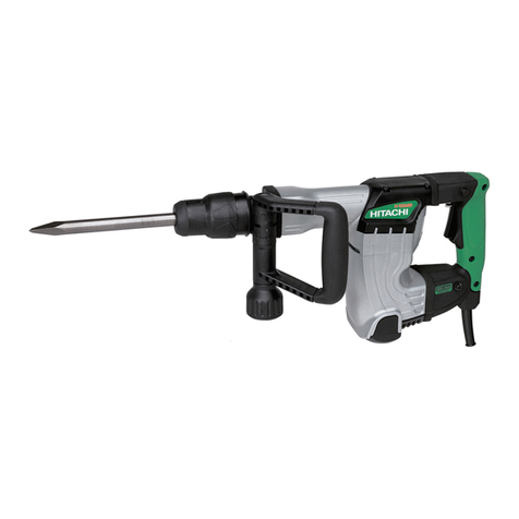
National Flooring Equipment TROLLEY User manual

SERVICE MANUAL
POWER HAMMER
Read Manual Before Servicing Machine
402984 Rev E


1
Table of Contents
Table of Contents...................................................................................................................................... 1
Section 1 – Technical Data ............................................................................................................................ 2
1.1 Specifications ...................................................................................................................................... 2
1.2 Applications and Proper Use............................................................................................................... 2
Section 2 – Safety Regulations...................................................................................................................... 3
2.1 Warnings ............................................................................................................................................. 3
2.2 Organizational Measures and Safety .................................................................................................. 3
2.3 Maintenance and Troubleshooting During Work ............................................................................... 4
Section 3 – Maintenance .............................................................................................................................. 4
3.1 Maintenance Information................................................................................................................... 4
3.2 Repairs ................................................................................................................................................ 5
3.3 Replacing the Chisel ............................................................................................................................ 5
Section 4 – Parts List and Diagrams .............................................................................................................. 6
Section 5 - Warranty ..................................................................................................................................... 8

2
Warning!
This machine is designed for working horizontal surfaces, specifically chiseling and demolition. All
other applications are deemed to be incorrect use. The manufacturers will not be liable for any
damage resulting from incorrect use. The user is solely responsible for any risk.
Section 1 – Technical Data
1.1
Specifications
Product Specifications
Max. Length
Typical
Operating
Length
Width
Max. Height
Weight
Speed
39” (99 cm) 24” (61 cm) 19” (48 cm) 44” (111.8 cm) 99 lbs (45 kg) Manual
Machine Variants
Region Serial Number Input Power Plug Type
Domestic TROLLEY-10XXXX 120V / 60 Hz 15A NEMA 5-15P Plug
International
TROLLEY-11XXXX 230V / 50 Hz EU1-16P, 250V, 16A Plug
TROLLEY-20XXXX 110V / 50 Hz IEC 60309, 16A, 3W Plug
1.2
Applications and Proper Use

3
Warning!
The max permitted noise level may be exceeded. Operators must wear noise-protective gear.
Caution!
Spare parts must conform to the manufacturer’s specifications. This is always guaranteed with NFE
original parts.
Section 2 – Safety Regulations
2.1
Warnings
Be aware of warning and cautionary information, designated by a gray text box. These areas will contain
information regarding dangers to the operator and/or the machine and instruction to prevent injury.
2.2
Organizational Measures and Safety
This instruction manual must be kept near the machine at all times.
Before starting any work with or on the machine, all authorized personnel must read the instruction
manual and, in particular, the section regarding safety instructions.
Appliances used in different locations must be connected via a current surge prevention switch.
Always wear goggles when using the machine. Wearing gloves, non-slip shoes, and an apron is
recommended.
Sawdust and splinters must be removed while the machine is running.
Extreme electromagnetic interferences from the outside could temporarily cause variations in the
rotation speed.

4
Warning!
All machinery can be dangerous for operating, maintenance, and repair personnel if used
incorrectly. Owners are responsible for compliance with safety regulations during operations and
maintenance of the safety devices supplied with the machine, and for providing suitable safety
devices. It is strictly prohibited to remove or change the security system of the machine!
2.3
Maintenance and Troubleshooting During Work
Disconnect machine from power supply prior to performing any maintenance. Only unplug or plug in
machine when it is turned off.
Keep mains lead clear of the machine during operation; always lead the cable away from behind.
The ventilation slots of the machine must be kept clear at all times. If the carbon brushes are worn, the
brushes should be exchanged and the tool should be sent to a service center for inspection.
Section 3 – Maintenance
3.1
Maintenance Information
Breakdowns caused by insufficient and unprofessional maintenance can lead to very high repair costs
and long downtimes. Regular maintenance is essential. Operational safety and the service life of the
machine depend on several factors, including proper maintenance.
The following table contains information on schedules, inspections, and maintenance for normal
working. The times are based on daily use. If the number of working hours shown here is not reached in
the corresponding period, the period may be extended. However, a complete inspection must take
place every year.
Because operation conditions can vary considerably, it is not possible to state in advance how often
checks for wear, inspections, maintenance, and repairs are necessary. A practical inspection schedule
should be drawn up taking the operating conditions into account. Contact NFE if you require further
assistance.
Warning!
Before beginning any repair work on the machine, make sure that it is turned off and disconnected
from the power source.

5
3.2
Repairs
It is recommended that the repairs are carried out by NFE or an authorized dealer.
Always keep stocks of spare parts that cannot be supplied at short notice. Production losses are usually
more expensive than the costs of the spare part. Any screws that are removed must be replaced in the
same quality and design. Only use NFE original parts.
3.3
Replacing the Chisel
1. Unplug the hammer.
2. Tilt the machine backwards, so that it lies with its handle on the floor.
3. With one hand, twist the chisel lock 180o; pull the chisel out with the other hand.
4. Hold the new chisel with the locking surface facing up, and slide the chisel in.
5. Turn the chisel lock back and ensure it is fixed in place.

6
Section 4 – Parts List and Diagrams
Item#
Part#
Spare Parts
QTY
Item#
Part#
Spare Parts
QTY
169
Handle upper part
1
232
Rubber bushing
4
202
402838
Rubber grip
2
233
Washer
4
203
Threaded rod M12
1
234
Hexagon screw
4
204
Shock-reducer
2
236
Lead wire 5m 2.5mm2
1
205
Star-shaped handle
1
237
Connection cable 2.5mm2
1
206
Rubber plate
1
238
Housing cpl. for HILTl
1
214
Hexagon screw
2
239
Hexagon nut
2
215
Locking ring
2
252
Threaded pin
2
216
Spacer
2
253
Threaded pin
1
217
Bolt
1
254
Safety nut
2
221
402840
Star grip
2
255
405105
Holder front upper part
1
222
Locking ring
5
256*
Clamping piece part front
1
223
Washer
2
257*
Clamping piece part back
1
225
Top mount
1
259 402842
Emergency stop switch
(-11XXXX machines only)
1
226
Carrier plate
1
227
Support for rubber bush.
2
260
Countersunk screw
2
228
Outer support
1
261
Allen screw
4
229
Safety nut
2
262
Baffle plate
1
230
Allen screw
8
263
Conduit gland
2
231
Locking ring
10
271*
Allen screw
2
*404651 Clamp and Screws Kit (not shown) includes Items 256, 257 and 271.

7
Item#
Part#
Spare Parts
QTY
Item#
Part#
Spare Parts
QTY
214
Hexagon screw
2
242
Locking ring
2
215
Locking ring
2
243
Spacer
2
216
Spacer
2
244
402841
Rubber wheel
2
217
Bolt
1
245
Distance washer
2
227
Support for rubber bush.
2
246
Spacer
2
232
Rubber bushing
4
247
Locking ring
2
233
Washer
4
248
Hexagon screw
2
234
Hexagon screw
4
249
403143
Locking ratchet plate
2
240
Chassis cpl.
1
250
Safety nut
2
241
Hexagon screw
2

8
Section 5 - Warranty
National Flooring Equipment Inc. (referred to as “The Company”) warrants that each new unit manufactured by
The Company to be free from defects in materials and workmanship in normal use and service for a period of
twelve (12) months from date of shipment from The Company to the end user. If shipment to end user is from a
Distributor, The Company may honor warranty for up to 15 months from initial shipment from the Company if the
end user can provide documentation of receipt date. Accessories or equipment furnished and installed on the
product by the Company but manufactured by others, including but not limited to: engines, motors, electrical
components, transmissions etc., shall carry the accessory manufacturers own warranty. Battery warranties are
prorated over the warranty period. Customer is responsible for the inspection of equipment or parts upon
delivery. Freight damages are excluded from this warranty.
The Company, at its determination of defect, will repair or replace any product or part deemed to be defective in
material or workmanship within specified warranty time period. All product determinations and / or repairs will
take place at The Company repair facility or at a certified warranty location designated by The Company. The
Company will coordinate and be responsible for all freight expenses associated with valid warranty claims. Freight
and shipping expenses associated with abuse or misuse will be back charged to the Distributor/Customer. The
Company reserves the right to modify, alter or improve any part / parts without incurring any obligation to replace
any part / parts previously sold without such modified, altered or improved part / parts. In no event shall the seller
or manufacturer of the product be liable for special, incidental, or consequential damages, including loss of profits,
whether or not caused by or resulting from the negligence of seller and / or the manufacturer of the product
unless specifically provided herein. This warranty shall not apply to any products or portions there of which have
been subjected to abuse, misuse, improper installation or operation, lack of recommended maintenance,
electrical failure or abnormal conditions, and to products which have been tampered with, altered, modified,
repaired, reworked by anyone not approved or authorized by the Company or used in any manner inconsistent
with the provisions of the above or any instructions or specifications provided with or for the product. Any and
all unauthorized onsite warranty work conducted by unauthorized personnel or any outside person(s), is not
covered by The Company unless the work has been pre-authorized by a predetermined manufacturer
representative. This warranty excludes wearable parts and/or consumables.
Defective or failed material or equipment shall be held at the purchaser’s premises until authorization has been
granted by The Company to return or dispose of defective products. Products returned to The Company for
inspection must be returned with a manufacturer authorized Return Material Authorization (RMA), and must be
packaged to The Company’s specifications to avoid damage during shipment. Any unauthorized return of
equipment will be declined at the dock by The Company. Any non-approved items returned with approved
returned items are subject to rejection and will not be credited. Credit will be issued for material found to be
defective upon The Company’s inspection based on prices at time of purchase.
TO OBTAIN SERVICE CONTACT NATIONAL FLOORING EQUIPMENT, INC. TOLL FREE AT 800-245-0267 FOR
A REPAIR AUTHORIZATION NUMBER. COD FREIGHT RETURNS WILL NOT BE ACCEPTED. FREIGHT
COLLECT SHIPMENTS WILL NOT BE ACCEPTED. WARRANTY REPAIRS MUST BE ACCOMPANIED BY DATE
OF PURCHASE RECEIPT AND A RETURN/REPAIR AUTHORIZATION NUMBER.
RETURN/REPAIR AUTHORIZATION NUMBER:
MACHINE SERIAL NUMBER:
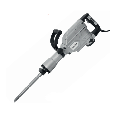
Table of contents