National Instruments NI 9919 User manual

INSTALLATION GUIDE AND SPECIFICATIONS
NI 9919
Shielded Rack-Mount Enclosure for CompactRIO and NI CompactDAQ
This document explains how to set up and install the National Instruments 9919 rack-mount
enclosure.
Caution National Instruments makes no product safety or CE marking compliance
claims for the NI 9919. The end user is responsible for conformity to any and all
compliance requirements.
Caution Do not operate or install the NI 9919 in a manner not specified in this
guide. Product misuse can result in a hazard. You can compromise the safety
protection built into the product if the product is damaged in any way. If the product
is damaged, return it to National Instruments for repair.
Caution The safety guidelines and specifications in this document are specific to
the NI 9919. The other components in the system might not meet the same
specifications. Refer to the documentation for each component in the system to
determine the safety ratings and specifications for the entire system.
Caution The NI 9919 requires a connection from the premise wire safety ground
to the earth ground terminal (protective earth). The earth safety ground must be
connected during use of this equipment to minimize shock hazards refer to the
Connecting Safety Ground section for instructions on connecting safety ground.
Before You Begin Refer to the documentation for your chassis and power supply
to find installation and grounding instructions specific to your devices.

2|ni.com |NI 9919 Installation Guide and Specifications
Figure 1. NI 9919 Parts Locator Diagram
1 NI 9919 Front View
2 NI 9919 Rear View
3 Removable Top Panel
4 Power Indicator LED
5 Optional Touchscreen Display
6USBPort
7 Rack Mount Rails
8 Rear Panel Captive Screws
9 I/O Connectors
10 Ethernet Ports
11 GPS Connector (TNC Style)
12 Fuse Holder
13 Power Connector with Backshell
14 Earth Ground Terminal (Protective Earth)
4
7
3
12
13
8
5
8
11
10
1
2
9
6
14

NI 9919 Installation Guide and Specifications |© National Instruments |3
Safety Guidelines for High Voltage
If you are installing high-voltage devices in the NI 9919, take the following precautions. The
NI 9919 has a high-voltage label on the inside of the back panel as shown in Figure 2.
Figure 2. NI 9919 High-Voltage Label
NI recommends you place an additional high-voltage label on the outside of the back panel in
the 2.0 in. × 3.5 in. area shown in Figure 3.
Figure 3. User-Placed High-Voltage Label
Caution Ensure that installation is performed only by qualified personnel.
Warning This icon denotes a warning advising you to take precautions to avoid
electrical shock.
1 High-voltage label on the inside of the back panel
1 User-placed high-voltage label on the outside of the back panel
1
1

4|ni.com |NI 9919 Installation Guide and Specifications
Caution The NI 9919 must be installed in a secure enclosure or a rack which is
accessible only by the use of a tool, as shown in Figure 4.
Caution A main input power switch or circuit-breaker must be included in the
installation as shown in Figure 4. The switch/circuit-breaker must be suitably located
and easily reached, and clearly marked as the power disconnect device for this product.
Figure 4. Secure Rack
1 Front view of secure rack
2 Rear view of secure rack
3 Main input power switch
4 NI 9919 inside a secure rack (front view)
5 Lock securing the rack
6 NI 9919 inside a secure rack (rear view)
6
5
4
5
3
12

NI 9919 Installation Guide and Specifications |© National Instruments |5
Accessing the NI 9919
The NI 9919 has a back panel that opens and removable top and bottom panels for accessibility.
Caution Ensure that installation and maintenance are performed only by qualified
personnel.
Opening the Back Panel
Complete the following steps to open the back panel of the NI 9919.
Figure 5. Opening the Back Panel
1 Unscrew the rear panel captive screws. 2 Pull the back panel down.
1
1
2

6|ni.com |NI 9919 Installation Guide and Specifications
Removing the Top or Bottom Panel
Complete the following steps to remove the top or bottom panel.
Figure 6. Removing the Top and Bottom Panels
NI 9919 Assembly Screws
The NI 9919 comes with 17 screws for assembly. Refer to Table 1 for screw descriptions.
1 Unscrew the 8 mounting screws for the panel. 2 Remove the panel from the NI 9919 enclosure.
Table 1. NI 9919 Screw Descriptions
Screw Use Quantity Description
USB Cable Mounting Screws 2Screw, M3X6, PHIL, PNHD, SS, Nylon Patch
Front Panel Mounting Screws 4Screw, M3X5, PHIL, FLHD, SS, Nylon Patch
Handle Mounting Screws 4Screw, M4X10, PHIL, FLHD, SS, Nylon Patch
Power Supply Mounting Screws 4Screw, M4X6, PHIL, PNHD, SS, Nylon Patch
Chassis Mounting Screws 3Screw, M4X25, PHIL, FLHD, SS
12

NI 9919 Installation Guide and Specifications |© National Instruments |7
Installing the Front Panel
Complete the following steps to install the NI 9919 front panel.
Figure 7. Installing the Front Panel
1 Install the power LED using a washer and nut.
2 Install the USB cable using two USB cable mounting screws.
3 Install the optional touchscreen display using the four screws included.
4 Install the optional touchscreen display power board using the four screws and four standoffs included.
5 Install the front panel using the four front panel mounting screws.
123
45

8|ni.com |NI 9919 Installation Guide and Specifications
Installing the NI 9919 Rack Mount Handles
Complete the following steps to install the NI 9919 rack mount handles.
Figure 8. Installing the Rack Mount Handles
1 Align the handle and handle mounting screws. 2 Tighten the handle into place.
21

NI 9919 Installation Guide and Specifications |© National Instruments |9
Installing the Fuse Holder in the NI 9919
Complete the following steps to install the fuse holder in the NI 9919.
Figure 9. Installing the Fuse Holder
The NI 9919 fuse holder supports two different fuse sizes. Use the appropriate fuse insert listed
in Table 2 for the size of fuse you want to use. Use the fuse size that is appropriate for your
application.
1 Align the fuse holder, gasket, and nut.
2 Tighten the fuse holder in place using the nut.
3 Install the fuse insert in the fuse holder.
Table 2. Fuse Inserts
Fuse Insert Color Fuse Size
Gray 1/4 in. × 1-1/4 in. (3AG)
Black 5 mm × 20 mm
123

10 |ni.com |NI 9919 Installation Guide and Specifications
Mounting the Chassis Directly to the NI 9919
The NI 9919 supports five mounting hole configurations that correspond to various NI chassis.
Table 3 shows the dimensions of the five mounting hole configurations. Visit ni.com/info
and enter 9919chassis for a complete list of chassis the NI 9919 supports.
Table 3. NI 9919 Mounting Hole Configurations
Configuration Chassis Mounting Hole Dimensions
1
2
3
4
5
5
5
4
3
5
22
1
165.1 mm (6.5 in.)
141.7 mm
(5.58in.)
47.2 mm
(1.86 in.)
69.9 mm
(2.75 in.)
47.2 mm
(1.86 in.)
158.3mm
(6.23in.)
40.6 mm
(1.60 in.)
303.3mm
(11.94 in.)

NI 9919 Installation Guide and Specifications |© National Instruments |11
Mounting a Power Supply in the NI 9919
The NI 9919 supports the panel mount method for an NI PS-14/15 power supply. Use the
mounting holes shown in Figure 10 and the four power supply mounting screws to panel mount
your power supply.
Figure 10. NI 9919 Power Supply Mounting Holes
Note NI does not recommend tapping the mounting plate.
Mounting Equipment on the Bottom Panel
The NI 9919 supports mounting of equipment and DIN rails using the mounting holes on
the bottom panel. Visit ni.com/dimensions for dimensions for the mounting holes on the
bottom panel.
1 Power Supply Mounting Holes
1

12 |ni.com |NI 9919 Installation Guide and Specifications
Grounding the NI 9919
NI requires that you connect the NI 9919 to earth ground (protective earth) and ground the
chassis and power supply.
Connecting Safety Ground
NI requires that you connect the NI 9919 to earth ground (protective earth) using the following
steps:
SAFETY GROUND CAUTION Connecting Safety Ground (Protective Earth)
The NI 9919 must have a safety ground (protective earth), which is connected by the
installer to the premise safety ground system for safe operation. The installer must
use a green or green/yellow wire for this purpose. The safety ground method shall be
reliable and meet applicable safety codes.
Figure 11. Safety Ground Terminal
1. Attach a ring lug to a green or green/yellow wire that is 2.58 mm2(10 AWG) or larger.
2. Remove the grounding nut from the safety ground terminal on the rear panel of the NI 9919.
3. Attach the ring lug to the safety ground terminal.
4. Tighten the grounding nut to 1.3 N · m (11.5 lb · in.) of torque.
5. Attach the other end of the green or green/yellow wire to the grounding electrode system
of your facility using a method appropriate for the application.
1 Safety ground terminal
1

NI 9919 Installation Guide and Specifications |© National Instruments |13
Grounding the Chassis and Power Supply
NI requires that you connect the chassis and power supply in the NI 9919 to the internal ground
screws shown in Figure 12. You can use any internal ground screw to ground the power supply
and chassis.
Figure 12. Internal Grounding Terminals on the NI 9919
1 Internal grounding screws on the front panel 2 Internal grounding screw on the back panel
1
2

14 |ni.com |NI 9919 Installation Guide and Specifications
Wiring Power Connections to the NI 9919
The NI 9919 provides a power connector with backshell and a safety ground terminal, as shown
in Figure 13. Connect neutral and line to the N and L terminals on the power connector and the
ground to the safety ground terminal.
Figure 13. Power Connector and Ground Terminal
1 Power connector with backshell 2 Safety ground terminal
1 2

NI 9919 Installation Guide and Specifications |© National Instruments |15
Connecting Custom Cables to the NI 9919
The NI 9919 has nine, eight-position barrier strip connectors on the rear panel for I/O
connections.
When connecting cables to the barrier strips, use ring or spade lugs to connect to the #8 stud
for outside connections and 0.25 in. wide female quick connects for the inside connections.
Terminate the cable shields to the chassis ground terminal adjacent to the barrier strip connector.
The NI 9919 includes 12 chassis ground terminals, as shown in Figure 14.
Figure 14. NI 9919 Chassis Grounding Screws
1 Chassis ground terminals
1

16 |ni.com |NI 9919 Installation Guide and Specifications
Rack Mounting the NI 9919
The NI 9919 supports rack mounting. Secure the NI 9919 to the rack posts using four mounting
screws appropriate for your rack and the top and bottom mounting positions on the rack mount
rails as shown in Figure 15. Using the middle mounting positions on the rack mount rails is
optional.
When placing the NI 9919 in a rack, avoid placing the enclosure above a heat source, as rising
heat can affect the operating temperature.
Caution You must install the NI 9919 in a rack prior to use.
Figure 15. Rack Mounting the NI 9919
Creating a Custom Back Panel
Visit ni.com/info and enter 9919bp for dimensions and information about creating a custom
back panel for the NI 9919.

NI 9919 Installation Guide and Specifications |© National Instruments |17
Specifications
This section provides specifications for the NI 9919.
Physical Characteristics
If you need to clean the NI 9919, wipe it with a dry towel or a soft-bristle brush.
Weight............................................................... 12.27 kg (27.05 lb)
NI 9919 material............................................... Cold rolled steel
Finish ................................................................ Electroplated zinc on cold rolled steel
Dimensions ....................................................... 481.08 mm × 513.37 mm × 221.23 mm
(18.940 in. × 20.211 in. × 8.710 in.)
Note Visit ni.com/dimensions to find two-dimensional drawings and
three-dimensional models for the NI 9919.
I/O Connector Characteristics
Bare wire........................................................... 2.588 mm cross-section diameter (10 AWG) to
0.644 mm cross-section diameter (22 AWG)
copper conductor wire with 8 mm (0.31 in.) of
insulation stripped from the end
Ring/spade terminals
Stud size.................................................... 4 mm (#8)
Maximum width ....................................... 9.4 mm (0.370 in.)
Torque for barrier strips .................................... 1.4 N · m (12 lb · in.)
Torque for ground lug....................................... 1.4 N · m (12 lb · in.)
Power Connector Characteristics
Maximum current rating ................................... 10 A
Voltage rating1.................................................. 0 V to 250 V AC/DC
Input frequency................................................. 50/60 Hz
Screw-terminal wiring ...................................... 2.053 mm diameter (12 AWG) to 1.024 mm
diameter (18 AWG) copper conductor wire
with 7 mm (0.28 in.) of insulation stripped from
the end
Torque for screw terminals ............................... 0.5 N · m to 0.6 N · m (4.4 lb · in. to 5.3 lb · in.)
Ferrules ............................................................. 0.25 mm2to 2.5 mm2
1 Refer to the Safety Guidelines for High Voltage section for additional information about installing
high-voltage devices in the NI 9919.

18 |ni.com |NI 9919 Installation Guide and Specifications
Barrier Strip Connector Characteristics
Maximum current rating ...................................30 A
Voltage rating ....................................................0 V to 300 V
Environmental
Operating temperature1
(IEC 60068-2-1, IEC 60068-2-2)......................-40 °C to 55 °C
Storage temperature
(IEC 60068-2-1, IEC 60068-2-2)......................-40 °C to 85 °C
Ingress protection..............................................IP 30
Operating humidity (IEC 60068-2-56) .............10% to 90% RH, noncondensing
Storage humidity (IEC 60068-2-56) .................5% to 95% RH, noncondensing
Pollution Degree (IEC 60664) ..........................2
Maximum altitude.............................................2,000 m
Indoor use only.
Environmental Management
NI is committed to designing and manufacturing products in an environmentally responsible
manner. NI recognizes that eliminating certain hazardous substances from our products is
beneficial to the environment and to NI customers.
For additional environmental information, refer to the Minimize Our Environmental Impact web
page at ni.com/environment. This page contains the environmental regulations and
directives with which NI complies, as well as other environmental information not included in
this document.
Waste Electrical and Electronic Equipment (WEEE)
EU Customers At the end of the product life cycle, all products must be sent to
a WEEE recycling center. For more information about WEEE recycling centers,
National Instruments WEEE initiatives, and compliance with WEEE Directive
2002/96/EC on Waste and Electronic Equipment, visit ni.com/environment/
weee.
1 The NI 9919 operating temperature assumes the NI 9919 is housing a CompactRIO cRIO-9068 with eight
C Series modules installed and an NI PS-15 power supply. NI recommends that you verify the operating
temperature of the NI 9919 when using other hardware configurations.
⬉ᄤֵᙃѻક∵ᶧࠊㅵ⧚ࡲ⊩ ˄Ё RoHS˅
Ёᅶ᠋ National Instruments ヺড়Ё⬉ᄤֵᙃѻકЁ䰤ࠊՓ⫼ᶤѯ᳝ᆇ⠽䋼ᣛҸ
(RoHS)DŽ݇Ѣ National Instruments Ё RoHS ড়㾘ᗻֵᙃˈ䇋ⱏᔩ ni.com/
environment/rohs_chinaDŽ(For information about China RoHS compliance,
go to ni.com/environment/rohs_china.)

NI 9919 Installation Guide and Specifications |© National Instruments |19
Worldwide Support and Services
The National Instruments website is your complete resource for technical support. At ni.com/
support you have access to everything from troubleshooting and application development
self-help resources to email and phone assistance from NI Application Engineers.
Visit ni.com/services for NI Factory Installation Services, repairs, extended warranty, and
other services.
Visit ni.com/register to register your National Instruments product. Product registration
facilitates technical support and ensures that you receive important information updates from NI.
National Instruments corporate headquarters is located at 11500 North Mopac Expressway,
Austin, Texas, 78759-3504. National Instruments also has offices located around the world. For
telephone support in the United States, create your service request at ni.com/support or dial
1 866 ASK MYNI (275 6964). For telephone support outside the United States, visit the
Worldwide Offices section of ni.com/niglobal to access the branch office websites, which
provide up-to-date contact information, support phone numbers, email addresses, and current
events.

© 2014 National Instruments. All rights reserved.
376919B-01 Aug14
Refer to the NI Trademarks and Logo Guidelines at ni.com/trademarks for more information on National Instruments trademarks. Other
product and company names mentioned herein are trademarks or trade names of their respective companies. For patents covering National
Instruments products/technology, refer to the appropriate location: Help»Patents in your software, the patents.txt file on your media, or the
National Instruments Patents Notice at ni.com/patents. You can find information about end-user license agreements (EULAs) and third-party
legal notices in the readme file for your NI product. Refer to the Export Compliance Information at ni.com/legal/export-compliance
for the National Instruments global trade compliance policy and how to obtain relevant HTS codes, ECCNs, and other import/export data. NI MAKES
NO EXPRESS OR IMPLIED WARRANTIES AS TO THE ACCURACY OF THE INFORMATION CONTAINED HEREIN AND SHALL NOT BE LIABLE FOR
ANY ERRORS. U.S. Government Customers: The data contained in this manual was developed at private expense and is subject to the applicable
limited rights and restricted data rights as set forth in FAR 52.227-14, DFAR 252.227-7014, and DFAR 252.227-7015.
This manual suits for next models
1
Table of contents
Other National Instruments Enclosure manuals
National Instruments
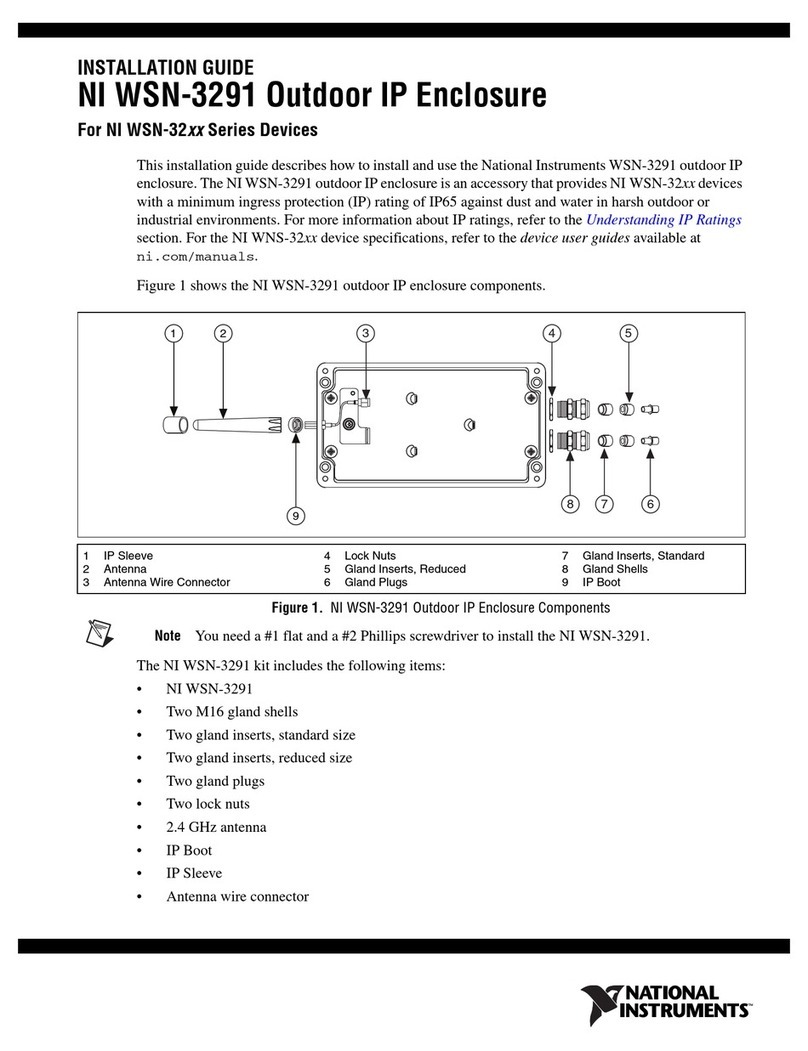
National Instruments NI WSN-3291 User manual

National Instruments
National Instruments CA-1000 User manual
National Instruments
National Instruments 9921 User manual

National Instruments
National Instruments WSN-3294 User manual

National Instruments
National Instruments NI 9921 User manual

National Instruments
National Instruments NI 9925 User manual

National Instruments
National Instruments Digilent Eclypse Z7 User manual
National Instruments
National Instruments WSN-3295 User manual