NexWatch PW-5000 User manual

TD1125 rev1101
PW-5000
Remote Enclosure
Installation Manual
Part Number: PW5K1ENC3


TD1125 rev1101
Installation Guide
PW-5000 Remote Enclosure—PW5K1ENC3 3
TT
TT
Table of Contentsable of Contents
able of Contentsable of Contents
able of Contents
Warnings and Cautions ........................................................................................ 4
Disclaimer........................................................................................................... 6
Product Liability; Mutual Indemnification................................................................ 6
Unpacking Procedure ........................................................................................... 6
Shipping Instructions ............................................................................................ 6
Limited Warranty ................................................................................................. 7
Confidentiality ..................................................................................................... 7
PW-5000 Remote Enclosure.................................................................................. 8
Description .......................................................................................................... 8
Dimensions ......................................................................................................... 8
Conduit Knockouts ............................................................................................... 8
Power Supply ....................................................................................................... 9
LED Diagnostics................................................................................................... 9
Backup Power Supply ........................................................................................... 9
Cables Supplied .................................................................................................. 9
Maintenance ....................................................................................................... 9
Operating Parameters.......................................................................................... 9
PW-5000 Remote Enclosure................................................................................ 10
Installation Instructions ....................................................................................... 11
Installation Diagram 1 ....................................................................................... 11
Installation Diagram 2 ....................................................................................... 12
Cable Specifications .......................................................................................... 13
NCI Cable Part Numbers ................................................................................... 14

4 PW-5000 Remote Enclosure—PW5K1ENC3
Installation Guide
TD1125 rev1101
Warnings and Cautions
WARNING
Before installation, TURN OFF the external circuit breaker which supplies power to the
system.
Before connecting the device to the power supply, verify that the output voltage is within
specifications of the power supply.
Do not apply power to the system until after the installation has been completed.
Personal injury or death could occur, and the equipment could be damaged beyond
repair, iftheseWARNINGS are notobserved!
WARNING
Fire Safety and Liability Notice
Never connect card readers to any critical entry, exit door, barrier, elevator or gate without
providing an alternative exit in accordance with all fire and life safety codes pertinent to
the installation.These fire and safety codes vary from city to city and you must get
approval from local fire officials whenever using an electronic product to control a door or
other barrier. Use of egress buttons, for example, may be illegal in some cities.In most
applications, single action exit without prior knowledge of what to do is a life safety
requirement.Always make certain that any required approvals are obtained in writing.DO
NOT ACCEPTVERBAL APPROVALS,THEY ARE NOTVALID.
NexWatch never recommends using the PW-5000 Series or related products for use as a
primarywarning or monitoring system.Primarywarningormonitoringsystemsshould
always meet local fire and safety code requirements.The installer must also test the
system on a regular basis by instructing the end user in appropriate daily testing proce-
dures.Failure to test a system regularly could make installer liable for damages to the end
user if a problem occurs.
WARNING
EARTH groundall enclosures, for proper installation.
WARNING
Use suppressors on all door strikes.Use S-4 suppressors for installation.NexWatch
recommends only DC strikes.
The information in this document is subject to change without notice.

TD1125 rev1101
Installation Guide
PW-5000 Remote Enclosure—PW5K1ENC3 5
CAUTION
IF ANY DAMAGETOTHE SHIPMENT IS NOTICED, A CLAIM MUST BE FILED WITH
THE COMMERCIAL CARRIER RESPONSIBLE.
CAUTION
Electro-static discharge can damage CMOS integrated circuits and modules.
To prevent damage always follow these procedures:
Use static shield packaging and containers to transport all electronic components,
including completed reader assemblies.
Handle all ESD sensitive components at an approved static controlled workstation.These
workstations consist of a desk mat, floor mat and an ESD wrist strap.Workstations are
available from various vendors.
NOTICE
THIS EQUIPMENT HAS BEENTESTED AND FOUNDTO COMPLY WITHTHE LIMITS
FOR A CLASS A DIGITAL DEVICE, PURSUANTTO PART 15 OFTHE FCC RULES
WHEN WIRED USING METAL CONDUIT FOR THE CABLING EXTERNAL TO THE
ENCLOSURE.THESE LIMITS ARE DESIGNED TO PROVIDE REASONABLE PROTEC-
TION AGAINST HARMFUL INTERFERENCE WHEN THE EQUIPMENT IS OPERATED
IN A COMMERCIAL ENVIRONMENT.THIS EQUIPMENT GENERATES, USES, AND
CAN RADIATE RADIO FREQUENCY ENERGY AND, IF NOT INSTALLED AND USED
IN ACCORDANCE WITHTHE INSTRUCTION MANUAL, MAY CAUSE HARMFUL
INTERFERENCETO RADIO COMMUNICATIONS.OPERATION OF THIS EQUIPMENT
IN A RESIDENTIAL AREA IS LIKELY TO CAUSE HARMFUL INTERFERENCE IN
WHICH CASETHE USER WILL BE REQUIREDTO CORRECTTHE INTERFERENCE
AT HIS OWN EXPENSE.
NOTICE
This document and the data in it shall not be duplicated, used or disclosed to others for
procurement or manufacture, except as authorized by and with the written permission of,
NexWatchThe information contained in this document or in the product itself is consid-
ered the exclusive property and trade secrets of NexWatch.Copyright laws of the United
States protect all information in this document or in the software product itself.
NOTICE
Any use of this product is subject to the terms and acceptance of the NexWatch Software
Agreement.Please request a copy from NexWatch, and review the agreement carefully.

6 PW-5000 Remote Enclosure—PW5K1ENC3
Installation Guide
TD1125 rev1101
Disclaimer
Product Liability; Mutual Indemnification
In the event that a Customer receives a claim that a Product or any component thereof
has caused personal injury or damage to property of others, Customer shall immediately
notify NexWatch in writing of all such claims. NexWatch shall defend or settle such claims
and shall indemnify and hold Customer harmless for any costs or damages including
reasonable attorneys’ fees which Customer may be required to pay as a result of the
defective Product or the negligence of NexWatch, its agents, or its employees.
Customer shall hold harmless and indemnify NexWatch from and against all claims,
demands, losses and liability arising out of damage to property or injury to persons
occasioned by or in connection with the acts or omissions of Customer and its agents and
employees, and from and against all claims, demands, losses and liability for costs of
fees,including reasonable attorneys’ fees,inconnectiontherewith.
Unpacking Procedure
CAUTION
If any damage to the shipment is noticed before unpacking, a claim must be filed with the
commercial carrier.
All containers should be opened and unpacked carefully in order to prevent damage to
the contents.The following steps are used to unpack equipment in preparation for instal-
lation:
1. Open the container and remove the unit(s) and all packing material.Retain the
container and all packing materials. They may be used again for reshipment
of the equipment, if needed.
2. Inspect the contents for shortage.If items are missing items, contact the order entry
department at 800-227-1667 Option-2.
3. Visually check contents. If damage is discovered, perform the following:
If shipping caused damage to the unit, a claim must be filed with the
commercialcarrier.
If any other defect is apparent, call 800-227-1667 Option-2 for a return authorization.
Shipping Instructions
To ship equipment back to NexWatch:
1. Contactthe customerservice department at 800-227-1667 Option-2beforereturning
equipment. Pleasehave the following availablewhencalling:
• A description of the problem or reason for returning the equipment.
• Original purchase order number, invoice number and if the unit is under warranty.
• A new purchase order number if the unit is not under warranty

TD1125 rev1101
Installation Guide
PW-5000 Remote Enclosure—PW5K1ENC3 7
2. From the customerservice department at, obtain the Return AuthorizationNumber
(RMA).
3. Show the RMA number on all packages shipped.Packages, which are not marked
with an RMA number will be refused at the factory and returned COD.
4. Carefully packtheequipmentfor shipment. Use theoriginalpackingmaterial when-
ever possible.
Limited Warranty
All Products sold or licensed by NexWatch include a warranty registration card which
must be completed and returned to NexWatch by or on behalf of the end user in order for
NexWatch to provide warranty service, repair, credit or exchange. All warranty work shall
be handled through Customer which shall notify NexWatch and apply for a Return Mer-
chandise Authorization (RMA) number prior to returning any Product for service, repair,
credit or exchange. NexWatch warrants that its Products shall be free from defects in
materials and workmanship for a period of two years from date of shipment of the Product
toCustomer.ThewarrantyonTerminals, Printers,CommunicationsProductsandUpgrade
kits is 90 days from date of shipment. Satisfaction of this warranty shall be limited to
repair or replacement of Products which are defective or defective under normal use.
NexWatch’warranty shall not extend to any Product which, upon examination, is deter-
mined to be defective as a result of misuse, improper storage, incorrect installation,
operationor maintenance, alteration, modification,accident orunusualdeteriorationof the
Product due to physical environments in excess of the limits set forth in Product manuals.
THEREARE NOWARRANTIESWHICH EXTENDBEYONDTHISPROVISION.THIS
WARRANTY IS IN LIEU OF ALL OTHERWARRANTIESWHETHER EXPRESS, IMPLIED
ORSTATUTORY, INCLUDING IMPLIEDWARRANTIES OF MERCHANTABILITYOR
FITNESSFOR ANY PARTICULARPURPOSE.NOREPRESENTATIONORWARRANTY
OFTHE DISTRIBUTOR SHALL EXTENDTHE LIABILITY OR RESPONSIBILITY OFTHE
MANUFACTURER BEYONDTHETERMS OFTHIS PROVISION.IN NO EVENT SHALL
NEXWATCH BE LIABLE FOR ANY RE-PROCUREMENT COSTS, LOSS OF PROFITS,
LOSS OF USE, INCIDENTAL, CONSEQUENTIAL OR SPECIAL DAMAGESTO ANY
PERSONRESULTING FROMTHE USE OF NEXWATCH’ PRODUCTS.
Confidentiality
All software, drawings, diagrams, specifications, catalogs, literature, manuals and other
materials furnished by NexWatch relating to the design, use and service of the Products
shall remain confidential and shall constitute proprietary rights of NexWatch and Customer
agrees to treat such information as confidential. Customer shall acquire no rights in the
design of the Products or the related materials except to use such information solely for
the purpose of and only during the time it sells the Products. Customer shall not copy the
design of any of the Products or use or cause to be used any Product design or related
materials for its own benefit or for the benefit of any other party.The covenants contained
in this section shall remain effective throughout the term of this Agreement and thereafter
unless specifically waived by NexWatch in writing.

8 PW-5000 Remote Enclosure—PW5K1ENC3
Installation Guide
TD1125 rev1101
PW-5000 Remote Enclosure
Description
The PW-5000 Remote Enclosure allows for a variety of system configurations.It can be
used in combination with the PW5K2ENC1, for example to place modules closer to the
doors they control. Or it can be used alone to house modules for a smaller system.
This enclosure can mount two full size PW-5000 panels (PW5K1IC, PW5K1IN,
PW5K1OUT, PW5K1R2) OR onefullsizepanel, onePW5K1R1 singlereaderpaneland
onePW5K1MX8multiplexerpanel.
The 2 amp power supply provides power for the modules.The battery is a 4.0 amp hour
batterycapable of providing 2.5to4hours backup, depending onconfiguration.
Dimensions
Height:14"(0,356m)
Width:16" (0,406 m)
Depth:4"(0,102 m)
Metal thickness: .05" (0,00127 m)
Color:Autumn White
Installation holes:Three hangers in a triangular pattern are provided for mounting the
cabinet.The top two are located .29" from the top and spaced 13.75 inches apart.The
lower hanger is located .930" from the bottom and 7.85" from each edge.See Enclosure
Drawing.
Conduit Knockout
½" (0,00127m) 2" (0,0508 m)
Top Side: 3 1
Bottom Side: 3 1
Right Side: 3 1
Left Side: 3 0
RearSide: 4 0

TD1125 rev1101
Installation Guide
PW-5000 Remote Enclosure—PW5K1ENC3 9
Power Supply
DO NOT USE POWER SUPPLYTO POWER LOCKS
- 12VDC 2 amp continuous power limited output with backup battery charging and
battery supervision.
- A 16.5VAC 20 VA wall transformer is provided.
- Requires 115VAC/60 hz.
- Maximum battery charge current .5 amp.
- AC on LED.
- AC Fail supervision.
- Low Battery Supervision (form “C” contacts).
- Short circuit and thermal overload protection.
Note: Allpower connection should be madewith18gauge or larger wiring.
LED Diagnostics
AC LED DCLED
ON ON Normaloperatingconditions
OFF ON Loss of AC, standby battery supplying power
ON OFF NoDC output
OFF OFF Loss of AC, Discharged or no Standby battery.No DC output.
Backup Power Supply
• Automatic Switch over to standby battery when AC fails (zero voltage drop).
• 4.0amp hour sealed rechargeable battery(BAT-3).
• Backup time: 1 hr.at maximum 2 amp current draw (longer for configurations with lower
current draw).
Cables Supplied
• Power On Light assembly.
• Tamper Switch assembly - Use ofTamper Switch is required by UL294.
Maintenance
• Replace the 12V 4 amp hour battery every 2 to 2.5 years.
• Oil the hinges on the door every 12 months.
Operating Parameters
• Temperature: 35° F to 110° F (2° C to 43° C).
• Operating Humidity: Up to 85% non-condensing.

10 PW-5000 Remote Enclosure—PW5K1ENC3
Installation Guide
TD1125 rev1101
BACK
.930
.4975
9.300
13.385
7.850
.975
14.725
.760
14.940
4.120
BOTTOM
.990
1.70
2.000
7.400
7.400
10.600
13.500
15.700
15.700
13.985
13.985
16.015
16.015
FRONT
LEFT SIDE
4.660
6.840
9.020
11.875
RIGHT SIDE
1.700
1.700
.990
4.660
4.660
6.840
9.020
9.020
11.875
11.875
13.675
13.675
TOP
2.200
2.200
5.100
5.100
8.300
13.700
.990
1.700
PW-5000 Remote Enclosure

TD1125 rev1101
Installation Guide
PW-5000 Remote Enclosure—PW5K1ENC3 11
Installation Instructions
1. Remove the 16.5V 20VA wall transformer from the enclosure.
2. Measure and install the top two mounting screws with heads smaller than .4" (0,1016
m) using proper mounting techniques for the material being used to hold the
PW5K1ENC3.Space the screws 13.75" (0,349 m) apart.Leave the screws exposed
approximately 1/2" (1.27 mm).
3. Open the door of the enclosure and place the hanging slots over the mounting screws.
Push the enclosure over the mounting screws and allow the screws to slide into the
slots. Finish tightening the mounting screws to securely hold the enclosure. Screw in
the lower hanger to secure the enclosure against the wall.
4. Run all appropriate wiring to the case through metal conduit. Mark each wire as to
the panel, location and input type. All cable shields should tie to the copper grounding
stud found on the bottom left of the enclosure.
5. Install the required panels onto the proper standoffs using the supplied screws.When
using two full size panels make sure the unused standoffs have nylon screws in
them to prevent short circuits on the panels.This enclosure can mount two full
size PW-5000 panels OR one full size panel, one PW5K1R1 single reader panel and
onePW5K1MX8multiplexerpanel.
6. Wire the readers, input and output connections (see wiring guide at end of booklet).
7. Check all connections prior to powering up the enclosure and panels.
8. Wirethepower supply through thewalltransformerprovided. Connect to theAC
terminals.Check the voltage at DC+ and DC-.The voltage should be approximately
13.8VDC.
9. Disconnectthepower.
10. Connect the DC power to the panels in parallel. Insure that the connection has the
correct polarity.Follow the wiring diagram supplied with the panels.
11. Wire the AC FAIL and LOW BATT normally closed to appropriate inputs on the panels.
Seeindividual panel wiring diagramssuppliedwiththe panels.
12. Connect the green and yellowTamper Switch wires to the appropriate inputs on the
panels.See individual panel wiring diagramssuppliedwiththepanels.
13. Connect Communicationswiring perthe wiringdiagramsuppliedwith the panels.
14. Attach the red battery charging connection to the positive terminal of the battery.The
negative connection is connected at the factory.
15. Check all connections prior to powering up the enclosure and panels.
Installation Diagram 1
W/KEY INSTALLED
SHOWN IN
LOCKED POSITION
SIDE VIEW
15
LOCK
BRACKET
1-REQ'D
12
12 PW-5000 Remote Enclosure—PW5K1ENC3
Installation Guide
TD1125 rev1101
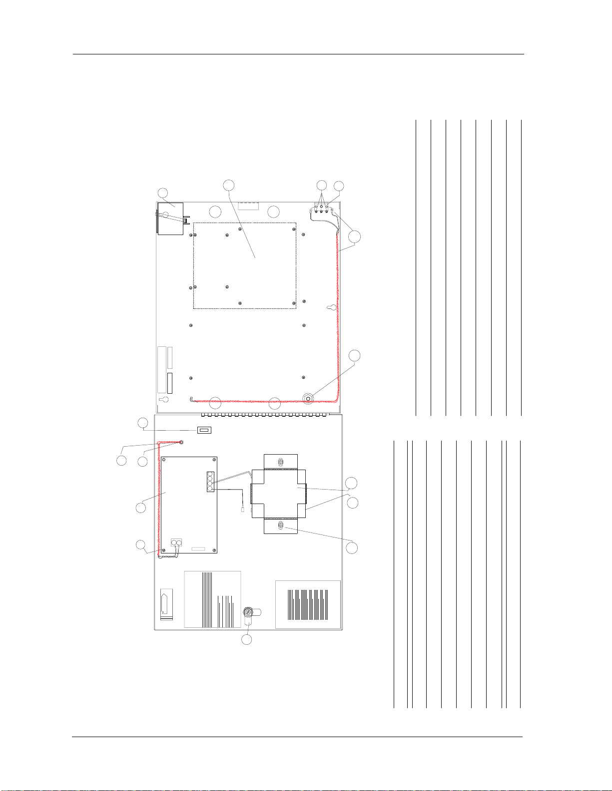
Installation Diagram 2
Left Open View Right Open View
Part Description
1 Screw 6–32 x 1/4" 12
2 12 VDC Power Supply 1
3 Power Indicator Light Assembly 1
4 Retaining Ring 1
5 Kurly Lok 1
6 16.4 VAC 20 VA Wall Transformer 1
7 Nylon Screws 6–32 x 3/16"
8 KEPS Nuts 6–32 3
9 Tamper Switch 1
10 Tamper Switch Wire Assembly 1
11 Nuts 8–32 2
12 12 V Battery Bracket 1
13 12 V 4.0 amp hour Sealed Battery 1
14 Nut 1/4"–20 Hex with Nylon Insert 2
15 Lock with Key 1
TAMPER SWITCH
1-REQ'D
NUT 6-32 KEPS
3-REQ'D
YEL
GRN
FIRE SAFETY NOTICES ...
Notices
FCC-CDOC and
Fire Safety...
PLACE
STICKER
1/8" FROM
EACH EDGE
BRACKET
1-REQ'D
LOCK W/SF1400
1-REQ'D
BATTERY
1-REQ'D
12
13
8
9
10
15
ADD 2 TO STUD TAMPER SWITCH
WIRE SET
POWER IND LIGHT
WIRE ASSEMBLY
1-REQ'D
RETAINING
RING
1-REQ'D
3
4
14
AC AC
AC FAIL
NO
NC
NO
NC
LOW BAT
+BAT- +DC-
PLACE NYLON
SCREWS INTO
THESE 8 STANDOFFS
SN/1234 date
code
PRO22ENC3
WALL
TRANSFORMER
1 REQ'D (X-5)
6
7
2
1
CONNECT POSITIVE
TAB ON BATTERY
4 REQ'D 5
KURLY
LO K
11
PRO22E3PS
BAT-3
**IMPORTANT**
SUPPRESSORS MUST BE USED
WITH STRIKES, NORTHERN S-4
**IMPORTANT**
ENCLOSURE MUST BE
EARTH GROUNDED

TD1125 rev1101
Installation Guide
PW-5000 Remote Enclosure—PW5K1ENC3 13
Cable Specifications
Application NCI Part No. AWG Description Max. Dist. Imp. Cap.
N-485 connections NC2442-TN N/A Belden 9842 4000' (1200 m) 120Ω 12.8pf/ft
N/A or equivalent
CR-1, TR-1, CI-1, KR-1 NC1861-BL 18 6 conductor shielded 500' (152 m)
Wiegand card readers
NR-1 magstripe reader NC1861-BL 18 6 conductor shielded 500' (152 m)
PR-1-280 Cotag reader:
280 read head to SZC NC1861-BL 18 6 conductor shielded 300' (91 m)
SZC to N-1000-II NC1861-BL 18 6 conductor shielded 500' (152 m)
PR-2 Hughes reader:
scanner to reader NC1861-BL 18 6 conductor shielded 30' (9 m)
reader to N-1000-II NC1861-BL 18 6 conductor shielded 500' (152 m)
PR-3, PR-5 Indala readers:
A-3/A-5 read head to RE-2 NC18121-YL 18 12 conductor shielded 75' (23 m)
RE-2 to N-1000-II NC1861-BL 18 6 conductor shielded 500' (152 m)
PR-20 , PR-22 Indala readers:
A-20/A-22 read head
to RE-2 NC18121-YL 18 12 conductor shielded 75' (23 m)
RE-2 to N-1000-II NC1861-BL 18 6 conductor shielded 500' (152 m)
PR-10, PR-12 Indala readers: NC1861-BL 18 6 conductor shielded 500' (152 m)
HG-3 hand geometry reader: NC1861-BL 18 6 conductor shielded 500' (152 m)
5 conductor keypad NC1861-BL 18 6 conductor shielded 500' (152 m)
Alarm input points NC 2221-BR 22 2000' (610 m)
Relay outputs NC 1821-OR 18 twisted pair, shielded 2000' (610 m)
NOTE: FOR PLENUM RATED CABLE JUST ADD A “P”TO NEXWATCH’PART
NUMBERPREFIX;FOREXAMPLENC1861-BLBECOMESPNC1861-BL

14 PW-5000 Remote Enclosure—PW5K1ENC3
Installation Guide
TD1125 rev1101
NCI Cable Part Numbers
Part Number Description Application Length
NC1841-GY 18 AWG/4 conductor reader cable 1,000'
NC1861-BL-500 18 AWG/6 conductor reader cable 500'
NC1861-BL 18 AWG/6 conductor reader cable 1,000'
NC18121-YL-500 18 AWG/12 conductor keypad cable 500'
NC18121-YL 18 AWG/12 conductor keypad cable 1,000'
NCNET-1 50 ohm network cable 1,000'
NC2221-BR 22 AWG/2 conductor alarm cable 1,000'
NC1821-OR 18 AWG/2 conductor power/door cable 1,000'
NCC59206-BK RG-59 video cable 1,000'
NCP1841-GY 18 AWG/4 conductor Plenum reader cable 1,000'
NCP1861-BL-500 18 AWG/6 conductor Plenum reader cable 500'
NCP1861-BL 18AWG/6 conductor Plenum reader cable 1,000'
NCP18121-YL 18 AWG/12 conductor Plenum keypad cable 1,000'
NCP18121-YL-500 18 AWG/12 conductor Plenum keypad cable 500'
NCPNET-1 50 ohm Plenum network cable 1,000'
NCP2221-BR 22 AWG/2 conductor Plenum alarm point cable 1,000'
NCP1821-OR 8 AWG/2 conductor Plenum power/door cable 1,000'
NC2442-TN 24 AWG/120 Ω12.8pf RS-485 wire communication cable 1,000'
NC2442-TN 24 AWG/120 Ω12.8pf Plenum communication cable 1,000'


Your Access to the Future
47102 Mission Falls Court • Fremont, CA 94539 USA
Tel (510) 360-7800 • Fax (510) 360-7820
www.nexwatch.com
Other manuals for PW-5000
6
This manual suits for next models
1
Table of contents
Other NexWatch Enclosure manuals


Popular Enclosure manuals by other brands

Adamson
Adamson IS7px user manual

Vertiv
Vertiv Liebert ITA2 Quick installation guide

Mustang Sampling
Mustang Sampling Pony Installation operation & maintenance

CTC Union
CTC Union SCE Series product manual

Leviton
Leviton Opt-X 5WSML-02C Instructions for use

HP
HP D6000 Disk Enclosure installation instructions

Supermicro
Supermicro CSE-826BE1C-R609JBOD user manual

Rosewill
Rosewill STEALTH user manual

Amphenol
Amphenol Charles CUBE-PM628155N1 General description and installation

Mustee
Mustee DURAWALL 350 installation instructions

Tranberg
Tranberg TEF 1060 user manual

HP
HP BladeSystem bc2800 - Blade PC reference guide


