CHANGING OR ADDING OIL
Always change the oil in the compressor and the oil separator after recovery from a burn-out system.
1. Evacuate the unit by operating it in the “PUMP-OUT” mode
2. Turn off the unit and close all the valves.
3. Disconnect the unit from the recovery cylinder.
4. Open the discharge valve and turn the switch to “PUMP-OUT” for two seconds (DO NOT STAND INFRONT OF
THE DISCHARGE VALVE).
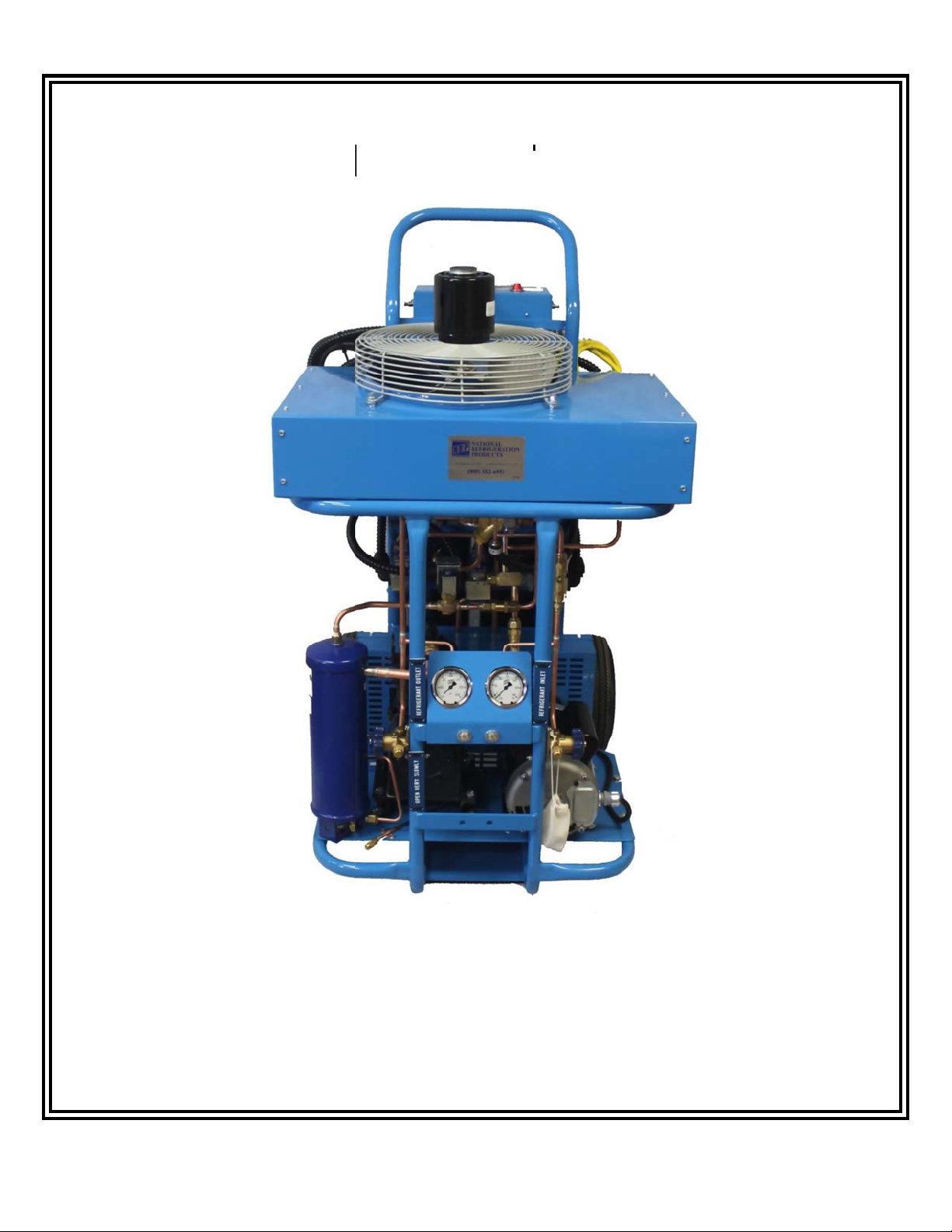
5. Disconnect the ¼” flare (cap and core) from the (tee) on the left side of the compressor (over the sight glass).
6. Place a container under the compressor oil drain fitting located on the left side of the compressor crankcase.
7. Remove the 1/4” flare cap and valve core, drain the oil, and replace the core tap.
8. Connect a hose to the tee on the left side of the compressor (over the sight glass) and place the other end into a
container with fresh refrigeration oil (500 viscosity NATIONAL 500). Run the compressor until there is a slight
vacuum showing on the suction gauge. Allow the oil to flow into the compressor until one quarter of the sight
glass is full. Remove the hose from the oil and allow its content to be drawn into the compressor. Repeat if
necessary. DO NOT OVERFILL!
9. Install the 1/4 “ flare cap and core in the tee at the left side of the compressor (over the sight glass)
10. Evacuate the unit by operating it in the “PUMP-OUT” mode with the outlet valve open to the atmosphere.
11. Close the refrigerant outlet valve.
PROCEDURE AFTER TRANSFERRING REFRIGERANT FROM A “BURN-OUT”
1. Drain the LV5 compressor and oil separator and replace with the appropriate amount of fresh refrigeration
oil. Remember to fill the LV5 with oil to proper level on sight glass.
2. Replace the filter-drier in the suction line.
3. Evacuate the LV5 recovery unit and hoses.
PROCEDURE TO FOLLOW BEFORE TRANSFERRING A DIFFERENT REFRIGERANT
1. Drain the LV5 compressor and oil separator and replace with appropriate amount of fresh refrigerant oil.
2. Replace the filter-drier in the suction line.
3. Evacuate the LV5 recovery unit and hoses.
PROCEDURE TO FOLLOW BEFORE TRANSFERRING A DIFFERENT REFRIGERANT
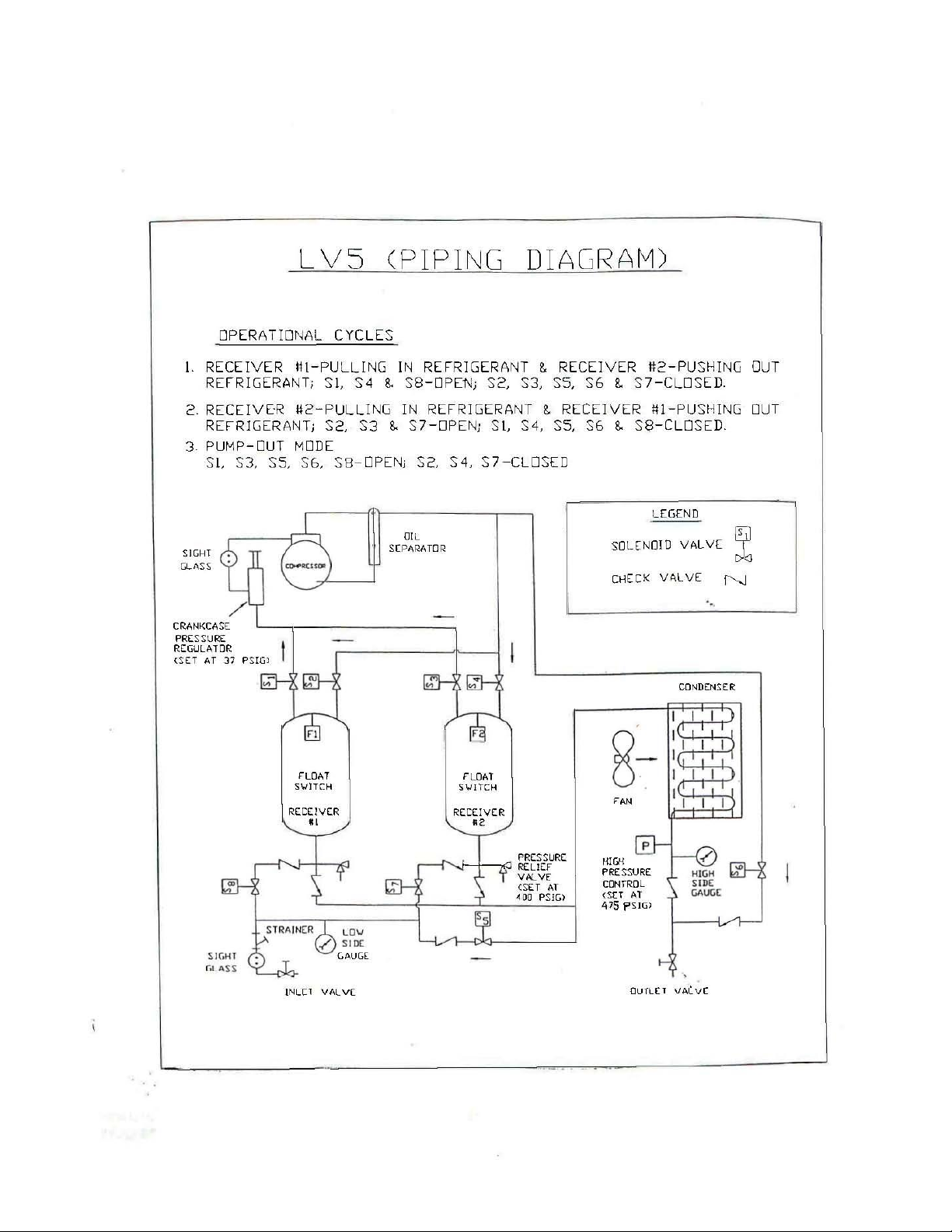
1. To avoid mixing different refrigerants in recovery cylinders always pump out the recovery unit at the end of each
transfer operation. This “PUMP OUT” operation will remove the refrigerant from the condenser, receivers and
internal piping of the recovery unit.
2. Replace the filter-drier in the suction line before recovering a different refrigerant.
3. Evacuate the recovery unit with a vacuum pump for 15 minutes or to 1000 microns. This evacuation will remove
any refrigerant left in the recovery unit.
4. To evacuate the recovery unit turn the “AUTO-MAN” switch to “AUTO”. Open the discharge valve (DO NOT
STAND INFRONT OF THE DISCHARGE VALVE). Turn the power switch to the “PUMP OUT” mode. This will
release a small amount of high pressure refrigerant through the discharge valve to the atmosphere. Connect a
vacuum pump to the discharge valve and evacuate is complete.
5. Mark the refrigerant number on each recovery cylinder at the time of recovery.
6. Remember that mixed refrigerants cannot be separated and that it is expensive to dispose of mixtures.
LV5. DOC 9/17/2018 7