TSR: CD Heartbeat is set in the Transmit Status Register;
Carrier Sense Lost is not set since it is generated by
the external encoder/decoder.
External Loopback through the TPI or CTI
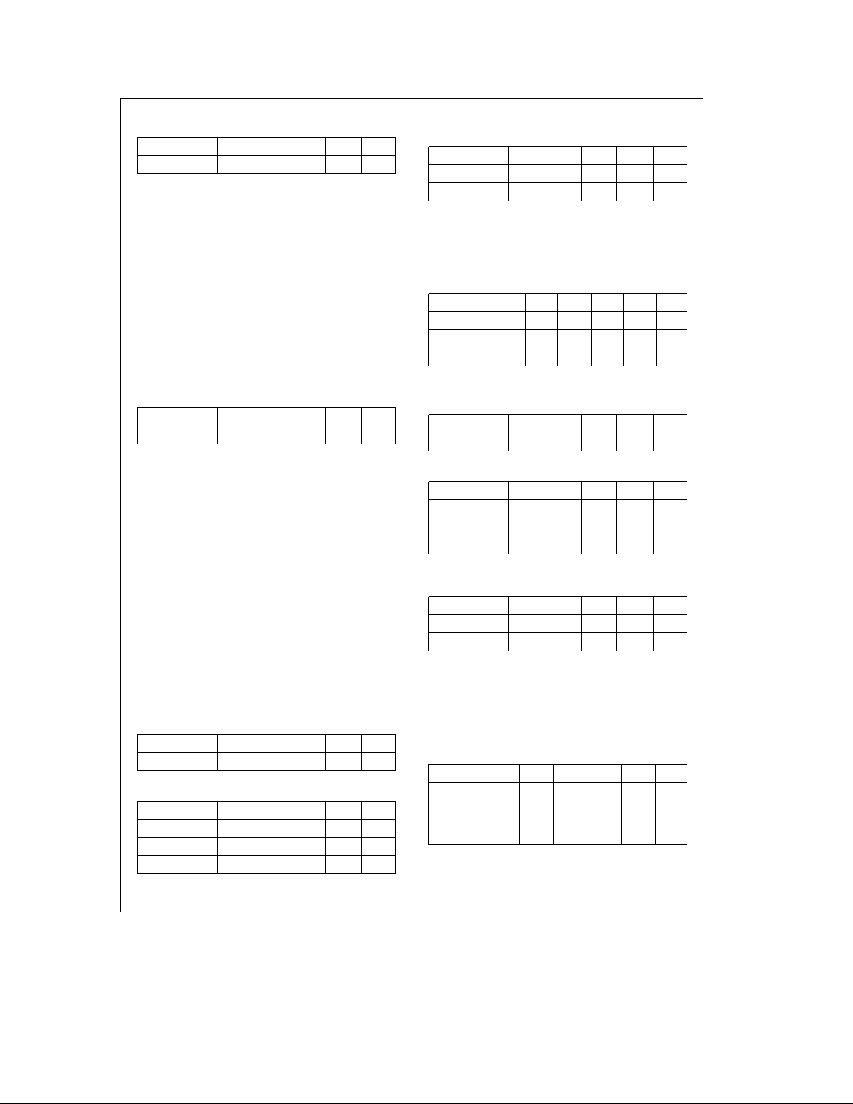
Loopback Path TCR RCR TSR RSR ISR
Mode 3 (TPI or CTI) 06H 1FH 01H 02H 06H
TSR: CD Heartbeat and Carrier Sense Lost should not be
set. The Transmit Status Register could, however,
also contain 01h, 03h, 07h, or a variety of other
values depending on whether collisions were en-
countered or the packet was deferred.
ISR: The Interrupt Status Register will contain 08H if the
packet is not transmittable.
General. During external loopback the NIC is now exposed
to network traffic. It is therefore possible for the contents of
both the receive portion of the FIFO and the Receive Status
Register to be corrupted by any other packet on the net-
work. Thus, in a live network, the contents of the FIFO and
Receive Status Register should not be depended upon. The
NIC will still abide by the standard CSMA/CD protocol in
external loopback mode (the network will not be disturbed
by the loopback packet).
6.2 GROUP II LOOPBACK TESTS : CRC RECOGNITION
The basic steps necessary to perform the Group II loopback
tests (in which a software CRC is appended to the packet)
are similar to those outlined previously for the Group I tests,
with the following exceptions:
1. The loopback packet created must have a software ap-
pended CRC.
2. When programming the Transmit Configuration Register
to the desired loopback mode, the Inhibit CRC bit must
be set.
3. After the loopback packet has been transmitted, check
the Interrupt Status Register and/or the Receive Status
Register for CRC errors. If a CRC error has occurred, the
loopback test has failed.
GROUP II RESULTS
The following examples show what results can be expected
from a properly operating NIC during Group II loopback op-
erations. The restrictions and results of each loopback
mode are listed for reference.
Internal Loopback through the NIC
Loopback Path TCR RCR TSR RSR ISR
Mode 1 (NIC) 03H 1FH 51H 01H 02H
TSR: Before transmission of the loopback packet, Carrier
Sense and Collision inputs are monitored (as re-
quired by CSMA/CD protocol). Once the NIC gains
access to the network for transmission, the Carrier
Sense and Collision Detect inputs are ignored.
Thus, the Carrier Sense Lost and CD Heartbeat bits
are always set in the Transmit Status Register.
ISR: Only the Packet Transmitted bit in the Interrupt
Status Register is set. The packet received bit is set
only if status is written to memory. In loopback this
action does not occur, hence the Packet Received
bit remains 0 for all loopback modes.
Internal Loopback through the SNI
Loopback Path TCR RCR TSR RSR ISR
Mode 2 (SNI) 05H 1FH 41H 01H 02H
TSR: CD Heartbeat is set in the Transmit Status register;
Carrier Sense Lost is not set since it is generated by
the external encoder/decoder.
External Loopback through the CTI
Loopback Path TCR RCR TSR RSR ISR
Mode 3 (TPI or CTI) 07H 1FH 01H 01H 02H
TSR: CD Heartbeat and Carrier Sense Lost should not be
set. The Transmit Status Register could, however,
also contain 01h, 03h, 07h, or a variety of other
values depending on whether collisions were en-
countered or the packet was deferred.
ISR: The Interrupt Status Register will contain 08H if the
packet is not transmittable.
General. During external loopback the NIC is now exposed
to network traffic. It is therefore possible for the contents of
both the receive portion of the FIFO and the Receive Status
Register to be corrupted by any other packet on the net-
work. Thus, in a live network, the contents of the FIFO and
Receive Status Register should not be depended upon. The
NIC will still abide by the standard CSMA/CD protocol in
external loopback mode (the network will not be disturbed
by the loopback packet).
6.3 Group III Loopback Tests: Address Recognition
The address recognition logic cannot be directly tested.
However, the CRC Error and Frame Alignment Error bits in
the Receive Status Register are set only if the address of
the packet matches the address filters. Thus, if errors are
expected to be set and they are not set, the packet has
been rejected on the basis of an address mismatch.
One method of testing the address recognition logic is to
transmit two loopback packets, one with a matching physi-
cal address, and one with a non-matching address and
compare the results. The basic steps necessary to perform
the Group III loopback tests are similar to those outlined
previously for the Group I tests, with the following excep-
tions:
1. RCR must be programmed to 00H. (The physical address
of the node must match the station address programmed
in PAR0-PAR5.)
2. Two loopback packets must be setup, one with a non-
matching physical address and one with a matching phys-
ical address.
3. Both packets must have a CRC appended by the NIC.
GROUP III RESULTS
The following examples show what results can be expected
from a properly operating NIC during Group III loopback op-
erations. The restrictions and results of matching and non-
matching addresses are listed for reference.
6