Naturela NPBC-V3C-K User manual

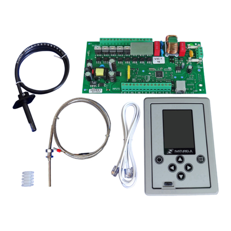
Electronic pellet burner controller – NPBC-V3C-K / NPBC-V4C-K / NPBC-V4E-K
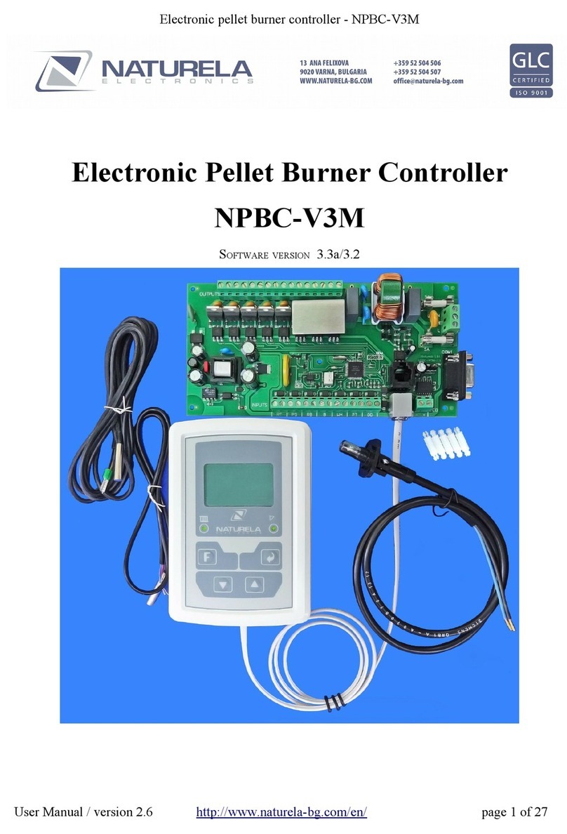
Electronic Pellet Burner Controller
FOR DRY PELLET STOVE
NPBC-V3C-K
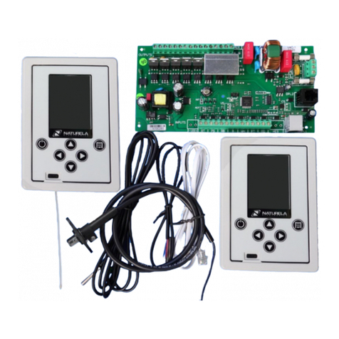
NPBC-V4C-K
NPBC-V4E-K
SOFTWARE VERS ON 57/28
User Manual / ver3.8 Page 3 of 33

Electronic pellet burner controller – NPBC-V3C-K / NPBC-V4C-K / NPBC-V4E-K
CHANGES N MANUAL FOR THE WORK AND THE SOFTWARE OF THE CONTROLLER
User
Manual
version
Changes Pages
3.2 •Software version 27/14.
•New way of dismissing the alarms for registered problems. Most of
them are automatically dismissed as soon as the reason for them is no
longer present. Alarms caused by more serious events require manual
dismissal by pressing the left navigation button "◄" for more than 2
seconds.
•New appearance of the " nformation" screen and the "Equipment" menu
1
11
16
17
3.3 •Software version 28/14.
•Alphabetical order of the languages: Bulgarian, English, Latvian,
Portugal and Spanish.
•Added option to work with additional "Control module" with room
thermostat functions NRC-6 SV
3.4 •Software version 31/15.
•n case the burner is currently off (due to reached set temperature, for
instance), but it is about to turn on and if there is a timer scheduled to
turn it off in 10 minutes or less, the burner will remain off, because
otherwise the extinguishing procedure may begin before the fire is
stabilized.
•f OD input activates during gnition or Unfolding procedures, the
extinguishing procedure begins only after switching to any of the power
levels.
3.5 •Software version 32/16.
•f the burner is on and timers are active, holding the On/Off button for
more than 2 seconds deactivates the timers.
•Loading first dose time increased to 240 seconds
•Version screen displays software and hardware version of the controller,
as well as WiFi modem's software version if it is 24 or higher
18
22
3.6 •Software version 34/16.
•Main auger’s capacity increased to 350 kg/h.
•Consumed pellets graphic's scales increased to 5, 10, 20, 40, 80, 160
and 320 kg / h
•Minimum value for ignition/extinction level of illumination set to 1
•gnition's level of illumination value must be higher than extinction's.
•Added Russian language.
3.7 •Software version 46/20
•Switch mode choice between Standby, On and Timers
•New menu in User settings for fuel selection
User Manual / ver3.8 Page 3 of 33

Electronic pellet burner controller – NPBC-V3C-K / NPBC-V4C-K / NPBC-V4E-K
NTRODUCT ON
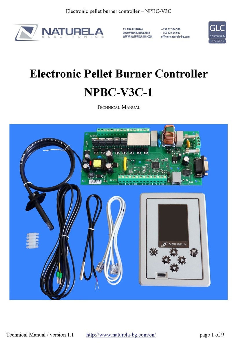
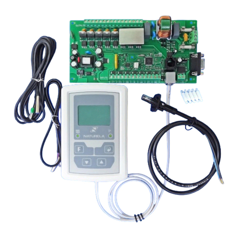
NPBC-V3C is a new updated version of the popular controller NPBC-V3M. t works with a new
Control module with a color TFT display NRC-6 and NPBC-V3M Executive module.
NPBC-V4C controller has the same functionality and a new improved executive module - NPBC-
V4 or NPBC-V4E.
This models' most important advantages are:
•Clearer and intuitive user interface with modern looking menus and 6 control buttons.
•Additional warning messages about incorrect parameter input or if parameters from a
different menu require corrections after the current changes.
•The Control module can be equipped with a WiFi module NRM-W3 for connection with the
Naturela remote monitoring and control system through the web.
•4 preset fuel profiles make switching between different fuels easier than ever.
•Statistical information about the fuel consumption divided by hour and based on a
calibrating constant parameter for the fuel auger's capacity.
•A list with short description, date and time of the occurred errors and any other event
concerning the controller's work.
•More parameters about the burner's work and current state displayed on the main screen at
the same time.
•A micro USB coupling on the face panel of the Control module for connection with a
computer with software for direct control and monitoring.
•
Controllers NPBC-V3C-K / NPBC-V4C-K / NPBC-V4E-K are designed to run burners that detect
the burning fire by measuring the temperature of the exhaust gases with a pt100 high temperature
sensor installed at the beginning of the vent. The pulsing control of the auger motor from the pellet
tank allows the precise dosing of the amount of pellets that goes to the burner. NPBC-V3C-K /
NPBC-V4C-K / NPBC-V4E-K can control an optional internal auger motor that forwards the
pellets inside the burner. The controller runs two blowers: one that provides the air to the burning
chamber and the other is an additional fan, for example, for taking out the exhaust gases, if
necessary. Both blowers' power can be adjusted from the controller. For more effective cleaning
process the controller can also run an additional powerful fan to blow away the ashes from the
burning chamber or a mechanical cleaning mechanism with an option to be run by one controlling
or powering up voltage. The controller runs a convection fan. Fan's switching on/ off depend on the
exhaust gases temperature.
All of the controlled mechanisms must work on 220VAC or 110VAC mains power supply!
mportant:
NPBC-V4C controller must be powered at least 3 minutes for normal operation of the clock
support system and burning process tracking when the power supply is switched off !
User Manual / ver3.8 Page 3 of 33

Electronic pellet burner controller – NPBC-V3C-K / NPBC-V4C-K / NPBC-V4E-K
MECHAN SMS AND SENSORS CONTROLLED BY NPBC-V3C-K OR NPBC-V4C-K OR
NPBC-V4E-K
•Electric feed screw motor to transfer the fuel from the bunker to the burner (power up to
180W).
•Electric internal auger motor to forward the fuel to the burning chamber (power up to
180W) .
•Main blower with smooth speed control to regulate the air flow (power up to 180W) .
•Additional cleaning fan (power up to 900W) .
•Exhaust gases fan with smooth speed control (power up to 180W) .
•Heating element to fire the pellets (power up to 850W) .
•Convection fan (power up to 180W).
•(Optional) Analog output for frequency inverter to power up a powerful air fan.
•High temperature sensor pt100 for fire detection by measuring the temperature of the
exhaust gases.
• Thermostat to control the back burning.
•Temperature sensor to control the room temperature.
•A potential free contact of a room thermostat for better control of the burning process
according to the room temperature.
•USB interface for connection with a computer.
NPBC-V3C-K / NPBC-V4C-K / NPBC-V4E-K NPUTS AND OUTPUTS
DESCR PT ON
Outputs nputs
FM Main fan RT Room thermostat. To this input could
be connected a normally opened or
normally closed contact, with no
additional voltage.
FSG Fan for the flue gases PS
SF Screw for fuel RB Reverse burning thermostat
SB nternal screw BRoom temperature sensor
PH Convection fan WH
PWH PT pt100 type exhaust gases sensor
GN gnition heater OD Opened door sensor switch
FC Fan for cleaning LED
ACF
User Manual / ver3.8 Page 3 of 33

Electronic pellet burner controller – NPBC-V3C-K / NPBC-V4C-K / NPBC-V4E-K
WAY OF OPERAT ON
A burner controlled by NPBC-V3C-K / NPBC-V4C-K can work in continuous automatic mode or
in timer mode. While in timer mode, the burner works only during the intervals of the day and the
days of the week set by the user. While working, it goes through several stages: cleaning, igniting,
unfolding the fire, modulated burning process according to the current and set temperature of the
boiler, intermediate cleaning performed during the burning process, extinguishing and cleaning
again. The current stage of the burner is displayed in green color on the bottom line of the main
screen.
Every ignition begins with a cleaning cycle to clean all leftovers of the previous burning. At first
only the main fan works for as long as it is set in the menu Factory Settings → Burning Setup →
Fuel X → Cleaning, line Start, column Fan. Then the Cleaning fan also starts and works for as
long as it is set in the same menu, line Start, column FC. The cleaning procedure is followed by the
igniting phase.
The ignition procedure starts with loading the first fuel dose in the burning chamber. The electrical
heater fires up the fuel while the fans provide the air flow. The procedure is performed in 3 stages.
During the first stage only the ignition heater works to reach the necessary temperature for ignition
faster. During the second and the third stages the ignition heater works along with the fans that
provide the necessary oxygen for the ignition and blow the heat from the heater to the fuel. t is
recommended to set lower speed for the fans during the second stage, so that they won't cool down
and blow off the flame and higher speed for the third stage to increase the air flow. To set the
maximum duration of each stage and the fans' speed go to the menu Factory Settings → Burning
Setup → Fuel X → gnition. The controller measures the temperature of the exhaust gases before
the beginning of the ignition by using the pt100 temperature sensor. After the ignition it starts
increasing and the controller constantly monitors the difference between the current temperature
and the initial value. f the difference is higher than the parameter for ignition in the menu Factory
Settings → Flame Detection the controller detects that the ignition is successful. The ignition heater
turns off and the burner goes to Unfolding fire phase to stabilize the fire. f the pellets do not ignite
during the set time for this, the burner loads a new portion and makes a new attempt for ignition.
This happens only for the first 3 ignition retries and the pellet portion for each of them is
respectively 100%, 50% and 25% of the set dose. After the last attempt for ignition, the burner stops
and displays an error message for ignition fail. The parameters for the first dose and the ignition can
be set in the menu as many retries as set in the menu Factory Settings → Burning Setup → Fuel
X → gnition. The parameters for detection of the burning fire can be set in the menu Factory
Settings → Flame Detection.
The successful ignition is followed by the smooth unfolding procedures. f the burner goes instantly
to burning on 3rd power level, when the fire is still unstable and the burning chamber is cold, the
high air flow from the fan might blow off or smother the flame. To avoid this, the burner waits for
the first dose of pellets to burn out and then slowly increases the power to the highest required
power level according to the temperature difference between the set temperature and the current
temperature of the boiler, starting with the lowest level P1. The parameters for the Unfolding fire
process can be set from the menu Factory Settings → Burning Setup → Fuel X → Unfolding
Fire.
The next phase is the burning control. NPBC-V3C-K or NPBC-V4C-K has settings for 4 different
power levels. Three of them are used for the burner's normal work. The 4th power level maintains
the burning fire to avoid unnecessary cycles of extinguishing, cleaning and ignition when the water
in the boiler has reached the set temperature. Of course, if there is no need for more heat in the
User Manual / ver3.8 Page 3 of 33

Electronic pellet burner controller – NPBC-V3C-K / NPBC-V4C-K / NPBC-V4E-K
heating installation for longer period of time, the burner turns off. The portion of pellets for each
power level is a function of the auger motor's capacity and activate time and the cycle between two
of its turnings on. The parameters for each power level's settings are auger motor's active time,
cycle between two turnings on and main and exhaust fans' speed. These parameters can be set in the
menus Factory Settings → Burning Setup → Fuel X → Setup P1/Setup P2/Setup P3/ Suspend.
n the beginning of every feeding cycle, the burner automatically chooses the best power level
depending on the difference between the set and the current temperature of the boiler. The
temperature difference for each power level, the maximum time for maintaining the fire (Suspend
power level) as well as the maximum temperature for overheating can be set in the menu Factory
Settings → Power Modulation. f the maximum time for Suspend power level runs out or if the
temperature of the boiler gets higher with as many degrees as set for overheating, the burner turns
off. While in Suspend mode, if the temperature difference reaches the set value for any of the power
levels and if there is still embers in the burning chamber, the burning process resumes directly to the
necessary power level.
The burner turns off because of several different reasons: automatically – because of no need of heat
anymore, or by timer, or because of an error that requires it to turn off (for example, Back burning),
or manually – from the Turn On/Off button or from a switch connected to the OD input. No matter
the reason or the way, the burner always performs the same extinguishing procedure. During the
extinguishing phase the fuel feeding stops and the fan keeps working slowly to help the last
remained pellets to burn out and to prevent back burning to the pellet bunker. Before the
extinguishing procedure, the controller measures the temperature of the exhaust gases. Then it
monitors the difference between the current and the initial value during the extinction. When the
difference gets equal or higher than the parameter for extinction in the menu Factory Settings →
Flame Detection, the controller detects that the fire is off. f the system cools down too slow and the
temperature is still high, the controller detects successful extinction after certain time, set in the
parameter “Extinguishing time” in the same menu.
During the cleaning phase the main fan works on 100% of its power. f there is an additional
powerful cleaning fan or mechanical cleaning system, connected to the FC output, it turns on, too.
The settings for cleaning before ignition, after extinction and in case of a problem are different. The
procedure is as follows:
1. The burner turns off.
2. The main blower turns on and works on maximum power for as long as it is in the
menu Factory Settings → Burning Setup → Fuel X → Cleaning, column Fan .
3. After the above time is up, the additional powerful fan or the mechanical cleaning
system connected to the FC output turns on and works along with the main blower for
as long as it is set in the menu Factory Settings → Burning Setup → Fuel X →
Cleaning, column FC
Besides the cleaning on start, stop and in case of alarm, the controller has an option for an automatic
cleaning procedures, which can be set from the menu Factory Settings → Burning Setup → Fuel
X → Cleaning. During these procedure the burner turns off, performs the procedure for Cleaning
on Stop and then turns on again.
As an additional cleaning method, some of the ashes from the burning process can be blown away
during the intermediate cleaning procedures that are performed while the fire is burning. During the
intermediate cleaning the FC output activates and/or the main and the exhaust fans' power can be
increased. The parameters for this procedure are: cycle for the procedure to repeat, duration of the
cleaning, fans' speed during the intermediate cleaning and whether the FC output will be active or
not. During this cleaning method the pellet feeding doesn't stop
User Manual / ver3.8 Page 3 of 33
Electronic pellet burner controller – NPBC-V3C-K / NPBC-V4C-K / NPBC-V4E-K
EXPLO TAT ON NSTRUCT ONS
NPBC-V3C-K / NPBC-V4C-K Control module has 6 buttons to navigate through the menus:
Controller's main screen appears shortly after turning the power supply on:
User Manual / ver3.8 Page 3 of 33
Data, burner's work phase
(table 1) or
registered error (table 2)
Menu /
Navigation buttons with different
functions depending on the current
menu
On/Off
Micro USB
Ambient Temperature
External stop activated
(OD nput)
Heating element ON
Fuel type
Main fan's speed
nformation fields with
an option to choos
between the displayed
parameters
Status bar with icons for
the outputs' current state and
the nternet connection
Time

Electronic pellet burner controller – NPBC-V3C-K / NPBC-V4C-K / NPBC-V4E-K
Animated moving pictures indicate when any of the auger motors or the main fan are currently
active. A flame in the boiler is a real time indication for the burning fire, detected by the photo
sensor. The messages on the bottom line of the screen appear in different colors depending on the
type of information they provide: white text for the date, green for the current work phase and red
for errors. f several messages must be displayed at the same time, they switch on every 4 seconds
The time must be set correctly for the burner to function properly. If it hasn't been set yet, its
indication is --:--
Most of the error messages that appear in red at the bottom of the main screen are indicated
by a three-toned sound signalization. In some cases the error message disappears soon after
the problem is resolved. Ho ever, there are some errors that if occur, remain on the screen
until the user dismisses them manually. Examples for such messages are “Back burning”,
“Boiler Frost”, etc. They can be cleaned only by pressing and holding the left navigation
button ( ◄ ) for 2 seconds, hile on main screen
The information fields to be displayed on the main screen from the following list:
con Displayed nformation
Exhaust's fan speed
nformation about the upcoming action of the timer. f there are no active
timers or the burner is in Standby mode, there is no information under the
icon. f there is at least one activated timer and the burner is ON, regardless
of the fuel type, the upcoming action (On/Off) and the time for it (or the
day of the week if it is after 23:59 pm on the current day) are displayed
under the icon.
Current calculated power of the burner. A calibrating constant parameter
for the auger motor's capacity must be set to assure the correct value of the
burner's power. The calibrating constant is available in the menu Factory
Settings → General Settings → Feeder capacity
Temperature measured by the exhaust gases high temperature sensor
Status bar icons description:
User Manual / ver3.8 Page 3 of 33
nternet connection
Active room
thermostat
Active FC output
Active convection fan

Electronic pellet burner controller – NPBC-V3C-K / NPBC-V4C-K / NPBC-V4E-K
How to turn the pellet stove on/off:
Press the On/Off button to enter the switch mode menu:
Press the up or down navigation buttons (▲ or ▼) to select a row and confirm your choice by
pressing the On/Off button. To abort your choice and return to the main screen press the left
navigation button (◄) or press no buttons for more than 5 seconds. The field “Fuel type” on the
main screen shows the currently selected fuel that the burner is set to burn. f this field is missing,
the burner is either off or is about to turn off. The most certain indication that the burner is off is
that there is no green text on the bottom line with any of the work phases from table 1.
Table 1
Work phase Work phase
1Cleaning 6Power P1
2Feeding 7Power P2
3gnition 8Power P3
4Unfolding fire 9nterm clean
5Suspend 10 Extinguishing
While in Standby mode, the burner doesn't work. f it was on right before switching to this mode, it
will instantly start the extinguishing procedure. t needs some time to completely put down the fire
and to perform the Cleaning on Stop procedure. The burner's and the boiler's aggregates might still
work for some time during the Standby mode.
The installations' circulation pumps keep orking until the conditions for them to ork are fulfilled,
even if the burner is off, thus ensuring the maximum usage of the heat energy.
The Fuel type field appears on the screen right after the burner is on. Then the Cleaning on Start
procedure and the ignition start if all of the necessary conditions are fulfilled: the temperature of the
boiler is lower than the set temperature, the room thermostat and the OD input for external stop
switch are not activated, there are no error messages or activated timers that require the burner to
stay off. All of the work phases (Cleaning, gnition, Unfolding fire, Power modulation, Suspend
User Manual / ver3.8 Page 3 of 33
Currently selected row

Electronic pellet burner controller – NPBC-V3C-K / NPBC-V4C-K / NPBC-V4E-K
mode and ntermediate cleaning) are executed according to the set parameters for the currently
selected fuel type.
While in Timers mode, the burner works only during the time intervals when its work is allowed.
These time intervals can be set from the menu Timers in User Settings. f Timers mode is selected,
but there are no active timers set, the burner remains off and a warning message is displayed on the
screen. As soon as any of the timers is activated, the burner will switch to Timers mode
automatically:
How to change the set temperature
Press the up or down navigation buttons (▲ or ▼) while on main screen to enter the Set
Temperature menu. Press the up or down navigation buttons again to change the value in the
relevant direction.
Hold the button to change the value with 5°C per second. Press the button (Menu) to save the
changes and return to the main screen or press no buttons for 5 seconds to exit the menu without
saving.
User Manual / ver3.8 Page 3 of 33
Electronic pellet burner controller – NPBC-V3C-K / NPBC-V4C-K / NPBC-V4E-K
Additional information and statistics
While on main screen, press the right navigation button (►) to access the additional information
and statistics screens.
Statistics charts about the pellet consumption
The first group of information screens is about the pellet consumption. Press the up or down
navigation buttons (▲ or ▼) to browse the charts for the last 4 days, starting with the current day.
The horizontal axis of the full screen histogram is equally divided for 24 hours and the vertical axis
represents the consumed pellets in kilograms. Above the chart is the corresponding date for the
currently displayed information and below is the total consumption for this day:
nformation about some of the current parameters
While on Pellet consumption screen, press the right navigation button (►) again to access the next
information screen. t provides information about the stove's set temperature, the domestic hot water
current temperature, the temperature of the exhaust gases, the exhaust fan's current speed and the
total pellet consumption since the last reset:
User Manual / ver3.8 Page 3 of 33
ndicator for
next page
Data format
Dd/mm/yyyy

Electronic pellet burner controller – NPBC-V3C-K / NPBC-V4C-K / NPBC-V4E-K
To reset the total pellet consumption press and hold the Menu button for more than 2 seconds.
To go back to Pellet consumption charts, press the left navigation button (◄).
nformation about the WiFi modem and the nternet connection
While on nformation screen, press the down navigation button (▼) to access the second page.
Description of the fields:
D – unique identification number for each modem
P – Modem's P address
WiFi mode – Modem's current state can be any of the following:
•dle – No connection with WiFi router
•Access point – The modem is waiting for the local WiFi network's SS D and password
•AP Associated – The modem is connected to a router
•nternet Access – Established internet connection
•Connected – The modem is connected to the information system's server
Snd/Rcv – Sent/Received data packages
f the control module NRC-6 is not equipped with a WiFi modem, there is only one message on the
screen:
User Manual / ver3.8 Page 3 of 33

Electronic pellet burner controller – NPBC-V3C-K / NPBC-V4C-K / NPBC-V4E-K
Diagnostics
While on any of the nformation screen pages, press the right navigation button (►) to access the
Diagnostics screen. To go back to the previous screen press the left navigation button (◄). This is a
listwith short description, date and time of every registered event or error message. Press the down
navigation button to check the older messages on the next pages if there are more than 4 entries. A
yellow star marks the newest entry. Hold the Menu button for more than 2 seconds to reset the
information.
Table 2 is a list of all the messages that can appear on this screen and their full description.
Messages from 1 to 13 also appear on the bottom line of the main screen.
In most cases of error messages, there is a three-tone alarm signal. Some of the error messages
automatically disappear after the reason for the message is no longer present. Others can be
dismissed by holding the left navigation button (◄) for more than 2 seconds hile on main screen.
Table 2
Message Clear the
error
method
Description
Back burning button „◄“ The thermostat for back burning situation has been
activated.
Off room TS automatically Boiler's temperature sensor is disconnected
Short room TS automatically Boiler's temperature sensor is on short
gnition fail button „◄“
Off PT Sensor automatically pt100 high temperature sensor is disconnected
Short PT Sensor automatically pt100 high temperature sensor is on short
High Flue gas temp button „◄“The exhaust temperature is too high
Flue gasses alarm! button „◄“The exhaust temperature is extremely high and the
burner has stopped
Menu settings --- Date and time of the last access to the Factory
Settings menu
User Manual / ver3.8 Page 3 of 33

Electronic pellet burner controller – NPBC-V3C-K / NPBC-V4C-K / NPBC-V4E-K
No Exec module --- No connection with the Executive module
Power On --- Date and time when the power supply to the
controller was turned on
Power Off --- Date and time when the power supply to the
controller was turned off
Begin --- Date and time when the controller's software or the
information in the Diagnostics screen has been reset
Automatic warning messages
n case of incorrect parameter input or if a change in the current menu caused changes in some of
the parameters from a different menu, the controller displays warning messages. For example:
Parameter settings
NPBC-V3C / NPBC-V4C has two main groups of parameters with an option for a different access
level to them: User settings and Factory settings. Press the Menu button once to enter the User
settings. They are available for any user at any time. Press and hold the Menu button for more than
2 seconds to enter the Factory settings. f the option for an access code has been activated, only
users who know it can access the Factory settings.
The controller has different types of menus. The examples below explain these types and the way to
set the parameters in each of them. Regardless the menu type, if no buttons are pressed for certain
time, the controller goes back to the previous screen or to the main screen. After adjusting the
parameters according to your needs, press the Menu button () to save your settings.:
•List choice – A red bar indicates the currently selected row. Press the up or down navigation
buttons (▲ or ▼) to move the bar and the right navigation button (►) to confirm the
selection. An arrow pointing down at the bottom of the screen or up on the top of the screen
indicates that there are more options in the corresponding direction outside of the visible area
of the screen. n this case, press the corresponding navigation button to go to the next or the
previous page. f there is an arrow pointing right on any of the rows on the screen, there is a
User Manual / ver3.8 Page 3 of 33

Electronic pellet burner controller – NPBC-V3C-K / NPBC-V4C-K / NPBC-V4E-K
sub-menu with list choice again. While looking at any screen with parameter settings, press the
left navigation button to go back to the previous screen with list choice.
•Parameter setting screen – At the moment when such a screen is displayed, a pink frame
marks the first editable parameter. The left and right navigation buttons (◄ ►) move the
frame to the previous or next editable parameter. The up and down navigation buttons (▲
▼) change the currently selected parameter's value or put/remove a check sign. The
parameter's type could be any of the following: editable numerical value, list with text
values or check box that activates/deactivates a certain function. The numerical parameters
are restricted in certain range of values. When the end of the range is reached, the value
stops changing, despite the remaining sound signal for pressed button.
Press and hold the left or right navigation buttons (◄ ►) to s itch bet een the parameters in the
current menu ith 5 positions per second.
Press and hold the up or do n navigation buttons (▲ ▼) to increase/decrease a parameter's value
ith 5 points per second or to bro se the list options in list choice menus ith 5 ro s per second.
User Manual / ver3.8 Page 3 of 33
Pink frame
That marks the
Current selected row
Check box
Parameter - checked
Editable numerical
Or text parameter
Additional information or
Parameter's name
Check box -
unchecked
Parameter type
LED - Active
Parameter type
LED - nactive
Additional information
Menu title
More options available
on the next page
An additional sub-menu
with list choice
Selected row
Screen title

Electronic pellet burner controller – NPBC-V3C-K / NPBC-V4C-K / NPBC-V4E-K
User settings
While on main screen, press the Menu button once to access the User Settings. Press the up or down
navigation buttons to move the red line that indicates the selected row. Press the right navigation
button to access the menu corresponding to the selected row:
Set Time & Date – The time format is 23:59 and the date format is dd/mm/yy. The day of the week
is automatically calculated after setting the date. After confirming the settings with the Menu
button, the seconds start from 0 only if the time has been changed. The automatic setting is
available only if the controller is equipped with a WiFi modem and connected through the nternet
to the Naturela's information system.
Language
Press the up or down navigation buttons (▲ ▼) to select the language for the controller's
menus and confirm your choice by pressing the right navigation button (►) or Menu
User Manual / ver3.8 Page 3 of 33
This option is available only
f the controller is equipped
with WiFi modem and has
an acess to the nternet
More options available on
The previous page
More optins available
on the next page

Electronic pellet burner controller – NPBC-V3C-K / NPBC-V4C-K / NPBC-V4E-K
Timers – Set and activate time intervals when the burner's work is allowed. f even one timer is
activated, the burner will work only during this interval. Moreover, the rest of the required
conditions must also be presented, such as: the work mode must be anything but “Standby”, the
temperature of the water in the boiler must be below the set temperature, OD and RT inputs must
not be active and there should not be any errors that require the burner to stay off.
The time in the column “On” must be before the time in the column “Off”! If necessary, set the
“Off” time first, to provide larger range for the “On” setting.
When using timers to control the burner, it is more convenient to get information about their current
state and their next action from one of the information fields on the main screen.
If there are active timers and the burner is turned on, the timers ill be excluded by pressing and
holding the button "On. / Off. " for more than 2 seconds.
User Manual / ver3.8 Page 3 of 33
Days of the week
Turn on the LEDs only fot
the days of the week when
this particular should be active
Light green LED - ON
Dark green LED - OFF
f there is a check sign,
the timer is active

Electronic pellet burner controller – NPBC-V3C-K / NPBC-V4C-K / NPBC-V4E-K
Select Fuel – Select the preset fuel profile settings corresponding to the currently used fuel. All
parameters for each profile must be set from Burning Setup menu in Factory Settings:
Display – Change the brightness of the display, if necessary
Convection Fan - Setting the temperature for switch on of Convection fan and hysteresis for
switched off. The switching on of this fan is according the temperature of the exhaust gases.
User Manual / ver3.8 Page 3 of 33

Electronic pellet burner controller – NPBC-V3C-K / NPBC-V4C-K / NPBC-V4E-K
Manual Feeding – Manual control of the fuel auger motor and the circulation pumps. This function
is useful to fill up the auger motor when it's empty, to measure its capacity of pellet feeding for
calibration purposes, to test the pumps or to fill up the installations with fluid. The up and down
navigation buttons (▲ ▼) check/uncheck the box to turn on/off the output and left and right
navigation buttons (◄ ►) switch between the parameters.
The maximum time for manual control is 370 seconds (6 minutes and 10 seconds). After that the
controller turns off the outputs and switches to the previous screen.
Follow these steps to calibrate the fuel auger motor:
1. Detach the auger from the burner, but not from the fuel bunker.
2. Turn on the manual feeding to fill up the whole auger with pellets. f 370 seconds are not
enough, repeat this step several times. When the auger is full stop the manual feeding.
3. Place a bucket or another tank at the end of the auger motor to collect the pellets.
4. Start the manual feeding again and leave the auger working for any exact period (see a list
with the recommended periods for this setting in table 3)
5. Remove the bucket and measure the weight of the collected pellets in kilograms.
6. Calculate the auger motor's capacity with the following formula:
Ac = F*C,
where Ac is the auger motor's capacity
•F is the weight of the collected fuel in kilograms
•C is the constant from table 3 corresponding to the active time of the auger motor during the
manual feeding, measured by the timer in the menu Manual Feeding
Table 3
Active time of the auger motor, measured by the timer in the menu Manual Feeding Constant C
120 seconds (2 minutes) 30
150 seconds 24
180 seconds (3 minutes) 20
240 seconds (4 minutes) 15
300 seconds (5 minutes) 12
User Manual / ver3.8 Page 3 of 33
Time for the auger's motor
active time

Electronic pellet burner controller – NPBC-V3C-K / NPBC-V4C-K / NPBC-V4E-K
360 seconds (6 minutes) 10
New WiFi network – f NRC-6 is equipped with a WiFi module for nternet connection, this menu
helps with its initial setting or when changing the WiFi network.
Press the Menu button () to exit this screen without making any changes. Press the down
navigation button (▼) to start the Access point mode. The controller shows the following screen:
User Manual / ver3.8 Page 3 of 33
New WiFi network's name
Confirmation for successful
network installation
This manual suits for next models
5
Table of contents
Other Naturela Controllers manuals

Naturela
Naturela NPBC-V3C-1 User manual

Naturela
Naturela NPBC-V6T-2 User manual

Naturela
Naturela NPBC-V3M-1 User manual

Naturela
Naturela NPBC-V3C-1 User manual

Naturela
Naturela NELBC-1 User manual

Naturela
Naturela NPBC-V3C-B User manual

Naturela
Naturela NPBC-V4E-1 User manual

Naturela
Naturela NPBC-V3C-2 User manual

Naturela
Naturela NPBC-V3M User manual
Popular Controllers manuals by other brands

Belimo
Belimo LRB24-SR-T Wiring diagrams

BRONKHORST
BRONKHORST EL-FLOW Prestige series instruction manual

BENDIX
BENDIX ULTIMATE TOW Installation & operating instructions

V-TAC
V-TAC VT-2472 manual

Samson
Samson TROVIS 5757-7 Mounting and operating instructions

BZ PRODUCTS
BZ PRODUCTS BZ 7/12 installation manual