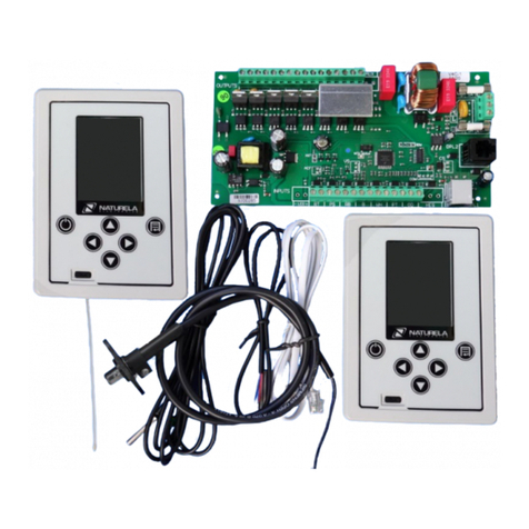
Naturela NELBC-1 User manual

Electric Boiler Controller NELBC-1
INTRODUCTION
Controller NELBC-1 is designed to be inst lled in three-ph se electric boilers h ving up to two
electric he ting elements - for he ting nd for domestic hot w ter (DHW). In its complete
configur tion the controller consists of executive module NEWHC1-3-2 to which ll components of
the he ting system re connected, two modules NEWHC1-3-2_TC th t control three-ph se electric
he ting elements, one for he ting nd one for DHW, nd control module NRC-8 MV th t provides
boiler's st tus visu liz tion nd llows setup nd control of boiler's oper tion. Option lly n
ddition l control module NRC-8 SV m y be connected. It functions s room thermost t s well
s sp re termin l for boiler's b sic control nd displ y of its st tus. The controller m y be used s
well in boilers th t h ve only he ting or only DHW function. In this c se only the components of
the ctive function h ve to be connected nd only one NEWHC1-3-2_TC is needed.
NELBC-1 llows flexible control of boiler's he ting elements providing m ximum comfort nd
energy s vings t the s me time. Modern user-friendly touch interf ce with gesture recognition
provides e sy n vig tion throughout inform tion screens nd settings menu. Context-dependent
virtu l keyp d nd icons th t represent the function of e ch button m kes the controller f st nd
e sy to setup nd oper te. The user c n directly set required he ting temper ture t the moment or
configure the weekly progr mmer for utom tic djustment of comfort temper ture in required
time-sp n of the d y. A complete configur tion boiler m y oper te in combined mode - he ting nd
DHW, only he ting or only DHW mode.
The controller continuously n lyzes the d t from sensors th t re connected to it nd the
me sured electric l v lues nd when devi tion in norm l oper tion of boiler is registered the
corresponding error mess ge is displ yed. The controller keeps di gnostics records of registered
events cont ining d te, time nd description of the event. Most of these events require user
intervention or service nd re therefore ccomp nied by udible sign l.
NELBC-1 h s built-in lgorithm to n lyze whether the electric he ting elements re in working
order. When this function is ctiv ted, during boiler oper tion the controller n lyzes the me sured
volt ges, currents nd power nd sign ls when registering nom lies th t m y be c used by f ulty
he ting element.
The controller llows, if necess ry, the output of the he ters to be further limited, sep r tely for
he ting nd for domestic hot w ter, for the purpose of economy or due to limit tions of the
electric l inst ll tion. Besides he ting elements, the controller lso controls the circul tion pump of
the he ting inst ll tion. Also, with the help of the corresponding sensor it monitors the pressure in
the system nd, if the v lues re outside the set r nge, displ ys n error mess ge, ctiv tes n
udible l rm, nd stops the he ters nd the pump in n emergency t low pressure, which is most
likely due to le k in the he ting system. The controller h s built-in function to protect the
he ting inst ll tion from freezing, which c n be ctiv ted if necess ry
In ddition to he ting, the boiler c n be used for screed drying, by ctiv ting speci l mode with
temper ture profile th t c n be configured ccording to the user's needs.
The built-in Wi-Fi module llows remote monitoring nd control of the boiler vi the Internet
through the N turel Sm rt Home system.
User M nu l / revision 1.2 http://www.n turel -bg.co m/ en стр. 3 от 36
Electric Boiler Controller NELBC-1
SENSORS AND MECHANISMS CONNECTED TO NELBC-1
•Temper ture sensor t the outlet of the he ting element for he ting
•Temper ture sensor t the tri cs th t control the he ting element for he ting
•Pressure sensor for he ting system
•Flow switch or flow r te sensor for he ting system
•Circul tion pump for he ting system
•Temper ture sensor t the inlet of the he ting element for DHW
•Temper ture sensor t the outlet of the he ting element for DHW
•Temper ture sensor t the tri cs th t control the he ting element for DHW
•Flow r te sensor for DHW
•Addition l control module NRC8-SV with thermost t function
•USB interf ce for softw re upd te by computer
User M nu l / revision 1.2 http://www.n turel -bg.co m/ en стр. 4 от 36

Electric Boiler Controller NELBC-1
CONNECTORS
OF EXECUTIVE MODULE NЕWHC1-3-2_MB
Heati g
BTO Temper ture sensor t the outlet of the he ting element for he ting
BTS Temper ture sensor t the tri cs th t control the he ting element for he ting
BPS Pressure sensor for he ting system
BFS Flow switch or flow r te sensor for he ting system
BSCR Connection to NEWHC1-3-2_TC module for he ting
Pump
HB Circul tion pump for he ting system
Domestic Hot Water (DHW)
WTI Temper ture sensor t the inlet of the he ting element for DHW
WTO Temper ture sensor t the outlet of the he ting element for DHW
WTS Temper ture sensor t the tri cs th t control the he ting element for DHW
WFS Flow r te sensor for DHW
WSCR Connection to NEWHC1-3-2_TC module for DHW
Commo
CM1 Connection to control module NRC-8 MV
CM2 Connection to ddition l control module NRC-8 SV
L1 Power supply ph se 1
L2 Power supply ph se 2
L3 Power supply ph se 3
NPower supply neutr l
User M nu l / revision 1.2 http://www.n turel -bg.co m/ en стр. 5 от 36

Electric Boiler Controller NELBC-1
BASIC PRINCIPLES OF BOILER OPERATION
The electric boiler controlled by NELBC-1 m y work both in both continuous nd timer mode
where the he ting works only within time interv ls defined by week progr mmer setup. Reg rdless
of the he ting timers set, domestic hot w ter he ting, when en bled, lw ys st rts when flow r te
sensor registers use of hot w ter. On st ndby st te, the boiler does not work neither for he ting nor
domestic hot w ter he ting, except for when frost protection function is ctiv ted, if en bled.
In order to void overlo ding the electric l inst ll tion, the he ting nd domestic hot w ter he ters
re not llowed to work t the s me time, nd when it is necess ry to turn on the domestic hot w ter
he ter, the other he ter is tempor rily switched off.
The output of the he ting elements is controlled precisely in order to m int in required temper ture.
As the he ter for he ting inst ll tion is turned on, the circul tion pump is lso utom tic lly turned
on, nd when the he ting is stopped, the pump continues to work for nother 5 minutes. When
he ting is st rted the output power is incre sed smoothly, which extends the life of the boiler nd its
dj cent components.
5 seconds fter the pump is turned on, the controller st rts to monitor whether the fluid in the
system is flowing. If the flow switch (flow r te sensor) does not detect fluid movement in the
he ting circuit, then the he ter nd pump re shut down nd "No Flow" error is ctiv ted. After 2
minutes n new ttempt is m de to turn on the he ting g in. If this time the sensor detects fluid
flow then the error is cle red, otherwise the he ter nd the pump re switched off g in. The
controller continues he ting re-st rt ttempts e ch 2 minutes.
While the pump is working the pressure is lso monitored. If me sured pressure is higher th n the
set m ximum v lue, only n error is ctiv ted. However, if pressure is below the minimum v lue, in
ddition to the error ctiv tion, the he ter nd the pump re turned off nd the boiler is switched to
St ndby.
The boiler is switched to St ndby whenever one of the following emergency situ tions:
•f ult of ny of the temper ture sensors (disconnected or short-circuit)
•neg tive temper ture t the outlet of he ting element for he ting or DHW
•overlo ding on ny of the ph ses of he ting element for he ting or DHW
•low pressure in he ting system
To st rt the DHW he ter, the flow r te sensor should me sure more th n 1 L/min. If the flow r te
f lls below 0.5 L/min then he ter is turned off. Accordingly when flow r te sensor is used in he ting
system, fluid flow is registered bove 1 L/min nd if the flow r te f lls below 0.5 L/min the
controller considers th t there is no flow. The m ximum flow r te v lue th t the controller shows is
25.5 L/min. If flow r te is higher then the v lue will be 25.5 L/min g in.
User M nu l / revision 1.2 http://www.n turel -bg.co m/ en стр. 7 от 36

Electric Boiler Controller NELBC-1
OPERATION INSTRUCTIONS
The controller h s 3.5" color IPS displ y with c p citive touch sensor. It is oper ted by touching
the displ yed virtu l buttons or ctive control re s, s well s by sliding the finger in cert in
direction (gestures).
When power supply is switched on, the controller displ ys its m in screen showing b sic
p r meters nd oper ting mode of the boiler.
M in displ y view in combined mode (He ting nd Hot w ter):
When he ter is on it is shown in red. Working pump is shown nim ted nd fluid flow in he ting
system is indic ted with moving rrow over the outlet pipe. When use of hot w ter is registered
then nim ted shower is shown. Whenever there is more th n one inform tion to be shown t the
bottom inform tion b r then the mess ges ch nge in turn e ch 4 seconds. The d te is shown in
white nd error mess ges - in red.
If system clock is not set then the controller will show --:-- . For boiler's normal operation the
system clock should be set correctly!
Most error messages are accompanied by a 3-tone audible signal.
ome error messages disappear automatically when the condition that caused the error is cleared .
Other errors, for example faulty heater , may be cleared only by holding button for one second .
User M nu l / revision 1.2 http://www.n turel -bg.co m/ en стр. 8 от 36
Clock
Volt ge nd
consumed power
He ting
outlet temper ture
D te or
error mess ge
M in screen
virtu l buttons:
- On / Off
- Set temper ture
- Settings menu
- Inform tion
- Reset of errors
Effective
set temper ture
for he ting
Flow indic tor
for he ting system
Pressure
in he ting system
He ter is
OFF
He ter is
ON
Top inform tion b r
cont ining st tus icons
nd other ddition l
inform tion
DHW
outlet temper ture
Use of hot w ter
nim tion
Working pump
nim tion

Electric Boiler Controller NELBC-1
Icons th t m y ppe r on the top inform tion b r:
Ico Mea i g
Room thermost t is ctiv ted (set temper ture is re ched / no he ting is required)
The controller is connected to the Internet vi Wi-Fi
He ting is stopped by timer
He ting is working ccording timer setup
M in screen view in only He tring nd only Hot w ter oper tion mode:
M in screen view in only He ting oper tion mode when "Floor he ting" is ctiv ted:
M in screen view in "Screed drying" mode:
User M nu l / revision 1.2 http://www.n turel -bg.co m/ en стр. 9 от 36
Floor he ting
inste d of r di tors
Current hour nd
tot l dur tion

Electric Boiler Controller NELBC-1
Ge eral User I terface Guideli es
Controller's displ y h s touch-sensitive p nel over the entire screen re . The controller is oper ted
through v riety of settings menu screens. Depending on the type of screen nd the type of
modified p r meter virtu l digit l or lph -digit l keyp d, delete button, n vig tion buttons, etc.
ppe r on the right-h nd of the screen. To "press" ny of the virtu l buttons, the corresponding
im ge of the button should be touched, prefer bly t its center in order to void the ctiv tion of
dj cent buttons.
When n ctive re of the screen is touched there is short beep. When button is pressed then it
"lights up". On settings screens p r meter l bels nd other ddition l inform tion re in green while
p r meter's v lues re in white. Current field which is modified is fr med nd highlighted. When
the p r meter is numeric then its v lue r nge ppe r in the field over the keyp d.
When the currently entered value is outside parameter's range then the field's frame becomes red.
In this case, changing the focus to another parameter or quiting the screen results in long beep and
the parameter revert to its previous value.
Required p r meter m y be re ched for modific tion by pressing buttons ◄ or ►, thus going
thtough ll p r meters in turn forw rd or b ckw rd ccordingly. However it is much e sier to
directly select the needed p r meter by touching its "virtu l re " where its v lue is displ yed.
User M nu l / revision 1.2 http://www.n turel -bg.co m/ en стр. 10 от 36
The p r meter
to be modified is m rked
V lue r nge
for current p r meter
S ve modified v lues
nd return
to previous screen
Delete
the right-most ch r cter
„Virtu l re “
Touch the re
of p r meter's v lue
to modify it
„Virtu l buttons“
to move to next or previous
p r meter
„Virtu l buttons“
Touch the re of
button's im ge to „press“ it

Electric Boiler Controller NELBC-1
On screens th t show list of options to choose from, the currently selected option is highlighted.
An option m y be executed by pressing button ►, while this option is highlighted or by directly
touching the line of the required option. When the list of options h s more line th t could be
displ yed on the screen then the list needs to be scrolled up or down so nother p rt of the list to be
visible. Scrolling m y be done using buttons ▲ nd ▼, which move the current selection in the
ccording direction. The e sier w y to scroll the list is to touch nd hold your finger on one of the
visible lines nd then, without t king the finger off the screen, move it to the required direction,
which will move the visible p rt of the list.
User M nu l / revision 1.2 http://www.n turel -bg.co m/ en стр. 11 от 36
Highlighted line
If „>“ is pressed then
this function
would be executed
Quit to m in screen
Quit to previous screen
Sign th t there is
sub-menu
Alph -numeric keyp d
Button to view
c pit l letters keyp d
Button to st rt
new sc n
for ne rby networks
Field to enter text,
for ex mple p ssword
Button Enter to
confirm filled in
inform tion

Electric Boiler Controller NELBC-1
When there is n option th t m y be ON or OFF ltern tively then there re two w ys to ch nge its
st te - through button on virtu l keyp d or by directly touching the switch which should on focus
lre dy. Have in mind that if the switch is not on focus then the first touch would bring it on focus
and the second touch would change its state.
M in screen buttons
Screen lock
User M nu l / revision 1.2 http://www.n turel -bg.co m/ en стр. 12 от 36
Button to ch nge
the st te of the switch
Switch is ON
Switch if OFF
Switch Mode
Ch nge
He ting Temper ture
M in menu
Inform tion screens
Cle ning error mess ges
Hold for 5 seconds
to unlock the screen
Are v il ble for
control by gestures
Slide direction
to view the first
inform tion screen

Electric Boiler Controller NELBC-1
Menu "Displ y" option "Auto Lock" ctiv tes utom tic lock of the screen 30 seconds fter the l st
ction. When the screen is locked then gestures do not work nd m in screen buttons re hidden.
The only ctive object is the unlock button , which should be held for 5 seconds to unlock the
screen. In order the boiler's st te to be visible without the need to unlock the screen, button is in
different color depending on boiler's st te, the s me color s the On/Off button which is not visible
on locked screen - red for "St ndby", green for "On" nd blue for "Timers".
Touching button shows number of different screens with ddition l inform tion. Ch nging
between these screens m y be done by n vig tion buttons ▲ / ▼ / ◄ / ► or by gestures - simply
swipe finger cross the displ y screen in the corresponding direction to switch to nother screen.
The swipe should be in horizont l or vertic l direction nd t le st h lf of screen size. St rting from
m in screen swipe to the left displ ys the following screens in sequence:
di gr ms "Electric Energy" → text inform tion screens → "Di gnostics".
A swipe to the right displ ys these screens in reverse order ending with m in screen.
When consumed electric energy di gr m screen is displ yed then swipe up displ ys the previous
d y, swipe down - the next d y. Simil rly when text inform tion screens re displ yed then the
following screens ppe r in sequence "Inform tion", "WiFi connections", "Version", "Re ltime
me surement d t " nd "N turel Sm rt Home App". However here screens re looped nd fter
"N turel Sm rt Home App" comes g in "Inform tion". Displ ying "Di gnostics" is simil r -
swipe up or down shows next or previous p ge, if there is more th n one p ge.
When using gestures to n vig te between screen the virtu l keyp d re should be voided to
prevent ccident l triggering of virtu l buttons.
User M nu l / revision 1.2 http://www.n turel -bg.co m/ en стр. 13 от 36
Are v il ble
for gestures
Swipe to the right
for m in screen
or swipe to the left
for text inform tion screens

Electric Boiler Controller NELBC-1
Switchi g the boiler o /off:
Pressing O /Off button displ ys list of v il ble modes to switch to:
The mode m y be ch nged by selecting different line with virtu l buttons ▲ or ▼ nd then
pressing button for confirm tion or directly touching the desired line without ddition l
confirm tion needed. There re three options: St ndby, On nd Timers. Timers mode is v il ble
only if system clock is set nd there is t le st one timer ctiv ted. Otherwise only St ndby or On
mode m y be selected. If button is pressed then the current mode is not ch nged. If no button is
pressed for more th n 5 seconds then the controller goes b ck to m in screen without ch nging its
mode of oper tion. The button O /Off on the m in screen is different color depending on current
mode - red for "St ndby", green for "On" и blue for "Timers".
When the boiler is in "St ndby" mode then it would not work unless nti-frost protection is
ctiv ted. It is norm l for the circul tion pump to continue working for 5 minutes fter switching to
"St ndby" mode.
When the boiler is switched on nd if He ting is ctive then effective set temper ture for he ting
will ppe r on the m in screen.
When "Timers" mode is selected then he ting would work only during time interv ls defined in
menu "Timers". If ll the timers re being de ctiv ted while the boiler is in "Timers" mode, then
he ting would stop nd on the bottom inform tion b r would be displ yed error "No ctive timers!".
In this situ tion if t le st one timer is ctiv ted g in then the boiler would continue to oper te in
"Timers" mode ccording to the ctive timers.
The hot w ter section of the boiler, if it is ctive, works ll the time both in "On" nd "Timers"
mode.
User M nu l / revision 1.2 http://www.n turel -bg.co m/ en стр. 14 от 36
Current selection
is highlighted
C ncel ch nge of mode
nd go b ck to m in screen
Confirm switch to
the selected mode

Electric Boiler Controller NELBC-1
When "Screed Drying" is ctiv ted (see menu "Screen Drying Progr m"), then set he ting
temper ture nd timers re ignored nd the controller follows the temper ture profile defined for
this speci l mode. In this c se the Switch mode screen is:
Set Heati g Temperature
Pressing button on the m in screen llows ch nging the he ting temper ture in "On" mode. This
temper ture is ignored in "Timers" mode since e ch timer h s its own set temper ture.
The temper ture m y be ch nged up or down by virtu l buttons "+" nd "-", in 1 degree steps. If
ny of these buttons is being held then the temper ture st rts to increment or decrement
utom tic lly 5 degrees per second. Button should be used to s ve the new temper ture nd go to
m in screen. If no button is pressed for more th n 5 seconds then the temper ture is s ved, if
modified, nd m in screen is displ yed.
The temperature may be also changed by a swipe up or down to increase or decrease it. A swipe to
the left may be used to confirm the new temperature and go back to main screen.
User M nu l / revision 1.2 http://www.n turel -bg.co m/ en стр. 15 от 36
Are v il ble
for gestures

Electric Boiler Controller NELBC-1
Additio al i formatio about boiler's operatio .
Pressing button on m in screen displ ys plenty of different inform tion screens. A swipe to the
left m y lso be used to switch from m in screen to inform tion screens. Addition l inform tion
screens re displ yed in three sections - st tistics s di gr ms, text inform tion nd di gnostics.
Electric E ergy - Hourly Statistics of Electric E ergy Co sumptio .
The first inform tion screen is "Electric Energy" nd cont ins di gr m for hourly electric energy
consumption for the the l st 4 d ys. First, inform tion bout the current d y is displ yed.
Inform tion bout the other d ys, if ny, m y be re ched pressing buttons ▲ or ▼ or using gestures
- swiping up or down. The d t is displ yed s histogr m on the entire screen. The horizont l xis
of the coordin te system is for the hours of the d y nd the vertic l xis is for the consumed
electricity in kWh. The d te is displ yed bove the di gr m nd below is the tot l consumed energy
for the d y.
I formatio - additio al parameter values.
When the controller displ ys "Electric energy" screen then pressing button ► displ ys
"Inform tion" screen. The s me m y be done by swiping to the left. This screen cont ins set
temper ture for he ting nd counters for tot l consumed energy t d y nd night r te since the l st
reset of these counters s well s the d te nd time of the reset, if done. If n ddition l control
module NRC-8 SV with thermost t function is connected then its set nd me sured room
temper ture is displ yed too.
User M nu l / revision 1.2 http://www.n turel -bg.co m/ en стр. 16 от 36
Sign showing th t there re
more inform tion screens
Form t of d te nd time
of couters reset:
DD/MM/YYYY HH:MM
Virtu l re for
energy counters reset

Electric Boiler Controller NELBC-1
The energy counters m y be reset by pressing nd holding for more th n 2 seconds the fr med re
cont ining energy counters. The d te nd time of this ction is s ved nd displ yed on the screen.
While "Inform tion" screen is displ yed, pressing ◄ switches b ck to previous screen - "Electric
Energy". The s me m y be done by swiping to the right.
WiFi co ectio s - I formatio about the WiFi module a d I ter et co ectio .
Getting from "Inform tion" screen to "WiFi connections" screen is done by pressing button ▼ or
swiping up. Also this screen m y be re ched directly from the m in screen by pressing the WiFi
indic tor on the top inform tion b r.
The fields re s follows:
ID – Unique identifier of the WiFi module
IP – IP ddress of the WiFi module
WiFi mode - Current st te of the WiFi module, m y be one of the following:
• Idle – No connection to WiFi router
• Access point – The WiFi module is in Access point st te nd w its to be configured for
Internet ccess
• AP Associated – The WiFi module is connected to the router
• Internet Access – Est blished connection to the Internet
• Connected – The controller is connected to the inform tion system server
Sеnd – Number of p ckets sent to the server
Receive – Number of p ckets received from the server
Errors – Number of p ckets received with error
Signal – Received sign l strength
In there is no WiFi module connected to the controller then inste d of the inform tion bove, there
would be mess ge "No Wi-Fi device".
User M nu l / revision 1.2 http://www.n turel -bg.co m/ en стр. 17 от 36

Electric Boiler Controller NELBC-1
Versio of hardware a d software of the co troller a d the WiFi module
Getting from "WiFi connections" screen to "Version" screen is done by pressing button ▼ or
swiping up.
Realtime measureme t data - Real-time i formatio about temperatures a d electrical values
Getting from "Version" screen to "Re ltime me surement d t " screen is done by pressing button
▼ or swiping up. Also this screen m y be re ched directly from the m in screen by pressing the
field th t cont ins volt ge nd consumed power.
Naturela Smart Home App - QR codes for the i stallatio of the mobile app
Getting from "Re ltime me surement d t " screen to "N turel Sm rt Home App" screen is done by
pressing button ▼ or swiping up.
User M nu l / revision 1.2 http://www.n turel -bg.co m/ en стр. 18 от 36
Softw re version of
the control module
Softw re version of
the executive module
Version of h rdw re nd
softw re of the WiFi module
Temper ture of the tri cs
th t control the he ter
Temper ture t the outlet
of the he ting element
Temper ture t the inlet of
the DHW he ting element
Ph se 1 Ph se 2 Ph se 3
Flow r te
Volt ge
Current
Power
Temper ture
of the built-in sensor
on the executive module

Electric Boiler Controller NELBC-1
Screed Dryi g - Diagram of the temperature profile for screed dryi g program
When "Screen Drying" is ctive then fter "N turel Sm rt Home App" screen there is ddition l
screen th t displ ys the currently set screed drying profile curve. The red vertic l line m rks the
current point of profile execution. Also t the bottom of the screen m y be seen in numbers the
current hour, the tot l dur tion of the progr m nd the dur tion of e ch interv l.
Diag ostics
Pressing button ► or swiping to the left, while ny of the text inform tion screens is displ yed,
le ds to "Di gnostics" screen which is list of inform tion bout e ch registered event with the d te
nd time of its occurrence. If there re more th n 4 records v il ble then buttons ▼ or ▲ m y be
used for n vig tion to next or previous p ge s well s swiping up or down. The st r symbol in front
of the d te m rks the l test registered event.
The mess ges th t m y be seen on this screen re listed in T ble 2. Mess ges from 1 to 32 m y lso
be seen s error mess ges on the bottom inform tion b r of the m in screen.
User M nu l / revision 1.2 http://www.n turel -bg.co m/ en стр. 19 от 36
Current hour
Dur tion of e ch st ge of
the screed drying progr m
Tot l dur tion
Symbol m rking
the l st event
D te nd time when the
event is registered
Description of the event
Indic tor th t there re
more p ges to be viewed
The red line m rks
the current hour of
progr m execution

Electric Boiler Controller NELBC-1
T ble 2
Message Reset of
Error Cause a d co seque ces
1 BTI TS disconnected utom tic The temper ture sensor t the inlet of the he ting
element for he ting is disconnected Not in use!
2 BTI TS on short utom tic The temper ture sensor t the inlet of the he ting
element for he ting is on short Not in use!
3 BTO TS disconnected utom tic
The temper ture sensor t the outlet of the he ting
element for he ting is disconnected. The he ting
element for he ting nd the pump re turned off nd
the boiler is switched to St ndby.
4 BTO TS on short utom tic
The temper ture sensor t the outlet of the he ting
element for he ting is on short. The he ting element
for he ting nd the pump re turned off nd the boiler
is switched to St ndby.
5 BTS TS disconnected utom tic
The temper ture sensor t the tri cs th t control the
he ting element for he ting is disconnected. The
he ting element for he ting nd the pump re turned
off nd the boiler is switched to St ndby.
6 BTS TS on short utom tic
The temper ture sensor t the tri cs th t control the
he ting element for he ting is on short. The he ting
element for he ting nd the pump re turned off nd
the boiler is switched to St ndby.
7 WTI TS disconnected utom tic
The temper ture sensor t the inlet of the he ting
element for hot w ter is disconnected. The he ting
element for hot w ter is turned off nd the boiler is
switched to St ndby.
8 WTI TS on short utom tic
The temper ture sensor t the inlet of the he ting
element for hot w ter is on short. The he ting element
for hot w ter is turned off nd the boiler is switched to
St ndby
9 WTO TS disconnected utom tic
The temper ture sensor t the outlet of the he ting
element for hot w ter is disconnected. The he ting
element for hot w ter is turned off nd the boiler is
switched to St ndby
10 WTO TS on short utom tic
The temper ture sensor t the outlet of the he ting
element for hot w ter is on short. The he ting element
for hot w ter is turned off nd the boiler is switched to
St ndby
11 WTS TS disconnected utom tic
The temper ture sensor t the tri cs th t control the
he ting element for hot w ter is disconnected. The
he ting element for hot w ter is turned off nd the
boiler is switched to St ndby.
User M nu l / revision 1.2 http://www.n turel -bg.co m/ en стр. 20 от 36
Table of contents
Other Naturela Controllers manuals

Naturela
Naturela NPBC-V3C-2 User manual

Naturela
Naturela NPBC-V3C-K User manual

Naturela
Naturela NPBC-V6T-2 User manual

Naturela
Naturela NPBC-V3C-1 User manual

Naturela
Naturela NPBC-V3M User manual

Naturela
Naturela NPBC-V3C-1 User manual

Naturela
Naturela NPBC-V3M-1 User manual

Naturela
Naturela NPBC-V3C-B User manual

Naturela
Naturela NPBC-V4E-1 User manual