NAUSICAA MAXXI UP 300 User manual

v02.12/14
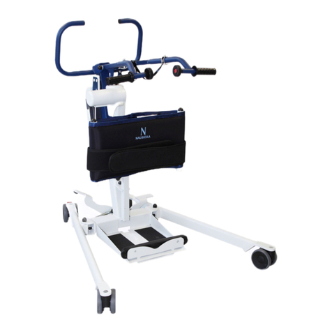
User Manual - Stand-Up Lift: MAXXI UP 300
Manufactured by NAUSICAA Médical S.A. / Approved by Ghizlane Labrosse (Biomedical Engineer)
MADE FROM ALUMINIUM
WEIGHT CAPACITY : 300 kg
CLASS 1 MEDICAL DEVICE
CONFORM TO STANDARD NF EN ISO 10535 : 2007
STAND-UP LIFT: MAXXI UP 300
www.nausicaa-medical.eu

User Manual - Stand-Up Lift: MAXXI UP 300
Manufactured by NAUSICAA Médical S.A. / Approved by Ghizlane Labrosse (Biomedical Engineer)

1
• Assembling Instructions
• Preventive Maintenance & Security Controls
• General Safety Guidelines
• Technicals & Dimensionals Characteristics
• Spare Parts
• Cleaning & Maintenance
• Motorization Technicals Characteristics
• Troubleshooting Guide
• Warranty
2-3
4-5
6
7
8
9
10-11
12
13
User Manual - Stand-Up Lift: MAXXI UP 300
Manufactured by NAUSICAA Médical S.A. / Approved by Ghizlane Labrosse (Biomedical Engineer)
Contents
User Manual / Stand-Up Lift: MAXXI UP 300

2
BEFORE USING YOUR STAND-UP LIFT, IT IS NECESSARY TO CHECK :
• The wheels turn and roll normally.
• The rear wheels function correctly.
• There is no wear or deformation on the hooks.
WARNING :
• To preserve the inserts, do not overtighten.
• Assembly is done with the brakes locked.
Step 1 :
- You have to find an item in the box.
- Your stander is ready for use.
1
Assembling Instructions
User Manual - Stand-Up Lift: MAXXI UP 300
Manufactured by NAUSICAA Médical S.A. / Approved by Ghizlane Labrosse (Biomedical Engineer)

3
Assembling Instructions
User Manual - Stand-Up Lift: MAXXI UP 300
Manufactured by NAUSICAA Médical S.A. / Approved by Ghizlane Labrosse (Biomedical Engineer)

4
1Connection head of the actuator (bolted)
2Connection base of the actuator (bolted)
3Connection head of the mast (bolted)
4Locking base of the mast
5Fixing of the castors (bolted)
6
Sliding of the sub-patellar support (adjustable knob)
7State and sticking of the anti-slip material
8Fixing of the mast handle
9
Overall state of the device (welds, joints, oxidation)
AOperation of the actuator
BOperation of the emergency system
CBatteries status (charge holding)
DHandcontrol status
Preventive Maintenance & Security Controls
Stand-Up Lift: MAXXI UP 300
Serial Number :
Control of security points (Frequency: depending on use, recommended every three months.
This is a sight control : any wear trace must lead to a replacement.)
GOOD WRONG DATE OF CHANGE
Control of electrical functions (Frequency: depending on use, at least once a year) this control
must be carried out when the hoist is loaded.
Inspection carried out on :
Inspection carried out by :
Date of the next inspection :
GOOD WRONG DATE OF CHANGE
User Manual - Stand-Up Lift: MAXXI UP 300
Manufactured by NAUSICAA Médical S.A. / Approved by Ghizlane Labrosse (Biomedical Engineer)

5
3
8
8
1Connection head of the actuator (bolted)
2Connection base of the actuator (bolted)
3Connection head of the mast (bolted)
4Locking base of the mast
5Fixing of the castors (bolted)
6Sliding of the sub-patellar support (adjustable knob)
7State and sticking of the anti-slip material
8Fixing of the mast handle
Periodical Greasing
WARNING :
DO NOT USE THE
DEVICE WITHOUT
THE SHIN BLOCK
THESE CONTROLS CAN BE CARRIED OUT WITHOUT LOAD
9OVERALL STATE OF THE DEVICE (WELDS, JOINTS, OXIDATION)
Preventive Maintenance & Security Controls
Control of security points (Frequency: depending on use, recommended every three months.
This is a sight control : any wear trace must lead to a replacement.)
User Manual - Stand-Up Lift: MAXXI UP 300
Manufactured by NAUSICAA Médical S.A. / Approved by Ghizlane Labrosse (Biomedical Engineer)
6
General Safety Guidelines
1. Use the Stand-Up Lift only for its intended purpose, in accordance with the legislation for medical devices, the
regulations for labor protection and accident prevention, as well as the generally recognized rules of technology.
2. Note that the Stand-Up Lift is a medical device, therefore the user is required to comply with the directive on the
use of medical devices.
3. The requirements for the electrical installation of the room or area where the Stand-Up Lift is used must meet
the current state of the technology.
4. Using the Stand-Up Lift only after being trained for its handling.
5. Before using the device, please read the complete User Manual in order to avoid damage due to improper
handling or exposure to risks. The User Manual contains important information and notes required for the Stand-
Up Lift use.
6. Use the Stand-Up Lift in accordance with this User Manual only. Keep the User Manual for future reference in
case of questions. Join this User Manual to the Stand-Up Lift in case of change of ownership.
7. Before any use, it must be ascertained whether the Stand-Up Lift and its accessories are in working order and in
impeccable conditions.
8. Before using the Stand-Up Lift with other medical and non-medical devices, check that the combination of these
products is allowed and can be used together safely.
9. Assembly, commissioning, maintenance and repair of the Stand-Up Lift should be entrusted only to specialists.
10. It is up to the user or operator to ensure (through adequate measures and instructions) that mechanical stress
of the charging cord (through bending, tension, shear, crushing) is excluded during loading or cleaning of the part.
This also applies to the electrical cables of other devices used with the Stand-Up Lift.
11. Respect the activation duration and the maximum weight capacity. These values must not be exceeded, otherwise
the Stand-Up Lift safe operation is no longer guaranteed.
12. Do not expose the Stand-Up Lift to direct sunlight or heat.
13. Ensure that no moisture enters the electrical system.
14. Avoid mechanical stress on electrical cords. Pull, bend or crush the cords may damage them.
15. Charge batteries in a well ventilated area.
16. Electromagnetic interferences can not be excluded from the Stand-Up Lift and other devices. If there is a risk of
such interference, the source of interference must be removed or the Stand-Up Lift should not be used.
17. Disruptions caused by the use of portable communication devices can not be completely excluded. This is why a
safe distance of at least 3 meters must be kept in order to ensure the functioning of the Stand-Up Lift safely.
18. Do not leave unattended children stand near the Stand-Up Lift.
19. The Stand-Up Lift should not be used as soon as abnormal noises, damages or any other malfunctions occur. In
this case, do not connect the wall charger to the Stand-Up Lift and inform us.
20. If damaged or defective, the Stand-Up Lift should not be used and should not be connected to the direct current.
Inform the dealer to remedy the default or failure.
User Manual - Stand-Up Lift: MAXXI UP 300
Manufactured by NAUSICAA Médical S.A. / Approved by Ghizlane Labrosse (Biomedical Engineer)
7
Dimensions (en mm)
1Highest Position /
2Maximal Reach Position /
3Minimal Reach Position /
aMaximal Reach at 600 mm 540
bMaximal Reach at the Base 480
cMaximal Height of the SCP 1490
dMinimal Height of the SCP 780
eLifting Lenght 710
fMaximal Internal Width 990
gInternal Width at the Maximal Reach 340
hMinimal internal Width 670
iMinimal Distance from Floor 30
jBase Height 110
kMinimal Distance Between the Wall and the
SCP at its Maximal Height 470
lMinimal Distance Between the Wall and the
SCP at its Maximal Reach 210
mMinimal Distance Between the Wall and the
SCP at its Maximal Height 190
nMaximal Diameter 1300
ij
m
l
k
c
d
e2
3
1
a
g
f
n
r
b
** SCP : Suspension central point
Technicals & Dimensionals Characteristics
• Frame made in aluminium
• Laser cutting and bending sheet metal, tubes and profiles
• Epoxy baked painting
• Ball bearing castors
• Total weight : 38 kg
• Weight capacity : 300 kg
• Lifespan : 8 years (except electrical parts)
* SCP : Suspention central point
User Manual - Stand-Up Lift: MAXXI UP 300
Manufactured by NAUSICAA Médical S.A. / Approved by Ghizlane Labrosse (Biomedical Engineer)
8
REFERENCES
DÉNOMINATIONS
FRAME
MU-BRS BRAS DE LEVAGE DE MAXXIUP 300
MU-CTB
SUPPORT DE CALE TIBIA DE MAXXI UP 300 (SANS MOUSSE D’APPUI SOUS ROTULIEN)
MU-MASR MOUSSE D’APPUI SOUS ROTULIEN POUR MAXXIUP 300
MU-RP3F PIED GAUCHE DE MAXXIUP 300
WP-ADAD ANTIDERAPANT ( 1 jeu de 2 pièces droite et gauche)
MU-G GUIDON MAXXIUP 300
MU-PD PIED DROIT DE MAXXIUP 300
MU-PG PIED GAUCHE DE MAXXIUP 300
MU-EP-ELEC
SYSTEME D’ECARTEMENT DES PIEDS pour MAXXIUP 300 (ROTULES + BIELETTES sans vérin)
WP-RJNFRD100 ROUE JUMELEE NOIRE A FREIN ROUGE DIAMETRE 100mm (roulement à billes)
WP-RJND100 ROUE JUMELEE NOIRE DIAMETRE 100mm (roulement à billes)
WP-BPGA9006 BOMBE DE PEINTURE GRIS ALUMINIUM 9006
WP-BPBA BOMBE DE PEINTURE BLEU ATLANTE
MOTORISATION
VSTLCM-ECP TELECOMMANDE 4 FONCTIONS UMEC VB
VS-CRTL CROCHET DE TELECOMMANDE UMEC VB
VSTLCM-ECP-FA FACADE ADHESIVE DE TELECOMMANDE 4 FONCTIONS
VS-BCAM CARTOUCHE AMOVIBLE DE BATTERIE UMEC VB (avec 2 batteries 5A/12V)
avec équilibrage et affichage de charge
F3-BT2IN JEU DE BATTERIES INTERNES 5A/12V
VS-BCAM-KCRT
KIT DE 2 CARTES (Equilibrage et affichage) pour cartouche batterie UMEC VB VS-BCAM
VS-BCAM-KCFC
KIT DE CONNEXION AVEC FUSIBLES pour cartouche batterie VS-BCAM OU VS-BCAM-SMP
VS-BCAM-CAR CARTER COMPLET CARTOUCHE BATTERIE UMEC VB
VS-BCAM-FAE FACADE ADHESIVE ECRAN CARTOUCHE BATTERIE VS-BCAM
VS-BCAM-CR CROCHET D’ATTACHE CARTOUCHE BATTERIE
VSBCC-ECP BOITIER DE CONTRÔLE UMEC VB 4 FONCTIONS (sans cartouche batterie)
VS-BCC-CCC CARTE DE COMMANDE AVEC CHARGEUR POUR BOITIER DE CONTRÔLE
UMEC VB 2 ET 4 FONCTIONS
VS-BCC-BA-ECP CARTE DE COMMANDE AVEC AFFICHEUR POUR BOITIER DE CONTRÔLE
UMEC VB 4 FONCTIONS
VS-KCNF KIT CONNEXION ET FUSIBLE POUR CARTE DE COMMANDE VS-BCC-CCC
VS-BAUR BOUTON D’ARRET D’URGENCE UMEC VB COMPLET
VS-BCH BOUCHON DE PRISE SECTEUR BOITIER DE CONTRÔLE UMEC VB
VS-CRD CORDON SECTEUR UMEC VB
VS-ERL CROCHET D’ENROULEUR DE CORDON SECTEUR UMEC VB
VSVRN-FSM10 VERIN UMEC 10000 N COURSE 290mm
VS-VRN-CHT CHAPE DE TÊTE DE VÉRINS AVEC DESCENTE D’URGENCE (tous modèles)
VS-VRN-10-CEMB CHAPE EMBASE DE VÉRIN DE LEVAGE 10000N (tous modèles)
VS-VRN-10-CAR CARTER PLASTIQUE POUR VÉRIN 10000N (tous modèles)
VS-VRN-KBPR KIT 2 BOUTONS-POUSSOIR ROUGE DESCENTE D’URGENCE MECANIQUE
DE VERIN (tous modèles)
VS-VRN-DM-CAR
CAPOT PLASTIQUE GRIS DESCENTE D’URGENCE MECANIQUE DE VÉRIN (tous modèles)
VS-VRN-DM CHAPE DE TÊTE DE VÉRINS AVEC DESCENTE D’URGENCE (tous modèles)
VS-VRN-10-CRD CORDON SPIRALÉ POUR VÉRIN 10000N (tous modèles)
VSVRN-ALECP VERIN UMEC 3000N NOIR POUR ECARTEMENT DES PIEDS
VS-CMB CHARGEUR MURAL POUR CARTOUCHE BATTERIE UMEC VB
Spare Parts
User Manual - Stand-Up Lift: MAXXI UP 300
Manufactured by NAUSICAA Médical S.A. / Approved by Ghizlane Labrosse (Biomedical Engineer)

9
BEFORE ANY HANDLING :
• Disconnect the AC power cord.
• Check that all electrical components are connected to each other.
• Clean electrical enclosures of the actuators and of the handsets, if they have been soiled by body fluids, especially
urine.
OBJECTIVE :
• Repair the stand-up lift and prevent the transmission of germs from one patient to another.
• Remove any organic soil by mechanical action (cleansing) or chemical action (disinfection).
CLEANING PROCESS :
• Clean the surfaces with a wet cloth by using an apropriate detergent.
• A regular cleaning is recommanded.
WARNING :
• The detergents used must have a neutral pH.
• Avoid the abrasive products and solvent, they could damage the device surface state.
DAILY MAINTENANCE:
• By means of a product applied on the surface in one operation.
• After the patient’s discharge by respecting the following operation:
- Cleaning is carried out by means of a cloth impregnated with a disinfectant solution surface.
• Maintenance by specific service providers after removal of the stand-up lift from the facility:
- Operation biological cleaning.
- Steam cleaning of various flat surfaces. Change surfaces regularly when washing to avoid water load. Steam clea-
ning of inaccessible areas. For tubes, steam use with a microfiber mop. Do not direct steam directly on the electrical
boxes.
CAUTION :
• Disinfection of actuators, electrical boxes and handsets with a microfiber cloth impregnated with disinfectant.
MONTHLY MAINTENANCE :
• Check that the device does not present any visible damages.
• Check that no part is missing.
• Check the good functioning of the castors and that no matter prevents their bearing.
• Check the good fonctioning of the commands as well as the connections of the remote control and the actuator
on the battery.
• Clean the sockets and the commands buttons with a dry cloth, if needed with a wet cloth.
• Check the good state of the electric cables.
Cleaning & Maintenance
User Manual - Stand-Up Lift: MAXXI UP 300
Manufactured by NAUSICAA Médical S.A. / Approved by Ghizlane Labrosse (Biomedical Engineer)

10
Device
class II
Motorization Technicals Characteristics
Battery Charging Diagram :
• Removable battery pack
• Digital display of the autonomy
• Emergency stop
• Electrical security lowering system
• Wall charger (in option)
• Remote control 4 functions Protection class IPX4
• Conform to Standard EN 60601-1 & EN 60601-2-38
• Manufactured according to Standard DIN/VDE 0700t238/1983
• DC motor low voltage 24V
• 24V / 120VA power
• Maximum strength : 10 000 N
• Lifting stroke : 29 cm
• Electronic protection when overloaded
• Protection class : II
• Protection type : IPX 4
• Stop limit switch
• Box in ABS
• Handcontrol with spiral cable, low voltage 24V
• Protection against overloading through thermo-switch
• Loudness : less than 55dB at a distance of 1 meter.
• Electromagnetic compatibility : conforms to EN 60601-1-2
User Manual - Stand-Up Lift: MAXXI UP 300
Manufactured by NAUSICAA Médical S.A. / Approved by Ghizlane Labrosse (Biomedical Engineer)

11
1
Cycle counter :
We have a time counter of 600,000 sec. If we consider that the actuator makes full strokes at an average speed of
9 mm/s that represents approximately 10,000 full cycles.
To check the number of cycles already performed, you must use the remote control 2 buttons:
-Press the 2 buttons at the same time.
The indication of the number-of cycles performed is indicated by the digits, the indication remains displayed for
about 3 seconds.
-If no digit is displayed the number of cycles performed is less than 150, 000 sec.
-If one digit appears the jack has been used for 150, 000 sec or 25% of the maximum time.
-If 2-digit appear, the actuator was used for 300, 000 sec or 50% of the maximum time.
-If 3 digits appear,the actuator was used for 450, 000 sec or 75% of the maximum time.
-If 4 digits appear,the actuator was used for 600, 000 sec or 100% of his time and the maximum box no longer work.
This counter work with time and not cycle because usual cycles counter count when you push on a remote control
button. The problem with this type of counter is when you push 5 times on one cycle, It’ll count 5 cycles. The time
counter is more accurate and after 10 000 full cycles the actuator need to be checked by the manufacturer.
- After 10,000 complete cycles, a key appears on the screen and the actuator must be checked.
Motorization Technicals Characteristics
Overload protection system :
• If you attempt to lift a person weighing beyond the maximum limit of the device, an anvil with “kg“ written will
appear asking you to immediately relieve the unit because it is a non-conform use.
Preservation system of the actuator :
• An integrated system for maintaining the actuator is included in the control box. It corresponds to a ratio between
the operating time and the rest time of the actuator.
• For 10% of usage time, it takes 90% of sleep time.
• For 6 minutes of continuous use, you must wait 54 minutes before you could reuse the device.
If this period is not respected, the device will not work and a jack will be displayed on the screen. When this cycle
is exceeded, there is a risk from overheating the equipment and cause a failure.
Soft stop and soft start Actuator Programming :
Push on the Emergency stop button
Push on button 1 and turn off the emergency stop button
The Control box Green led is flashing :
-3 times, Soft stop and soft start available
-2 times, Soft stop and soft start unavailable
Release button 1 on the handset after cessation of the green LED.
User Manual - Stand-Up Lift: MAXXI UP 300
Manufactured by NAUSICAA Médical S.A. / Approved by Ghizlane Labrosse (Biomedical Engineer)

12
User Manual - Stand-Up Lift: MAXXI UP 300
Manufactured by NAUSICAA Médical S.A. / Approved by Ghizlane Labrosse (Biomedical Engineer)
Problem Origin Solutions
The product, without patient, does
not go down.
Our products need some weight
to go down.
Push down on the lifting arm while
pushing the lowering button on the
remote control.
Mobile parts are too hard, product is
difficult to handle. Mobile parts need to be greased. Grease the mobile parts.
The actuator does not work but the
user can hear a “click in the control
box when the remote control button
is pushed.
1 . Batteries are unloaded.
2 . The actuator jack is not plugged.
3 . The actuator jack is deteriorated.
4 . There are damages on the actuator or
on the control box.
1 . Load the device.
2 . Plug the actuator jack.
3 . The actuator has to be repaired.
4 . The entire electric system has
to be checked.
The actuator does not work and the
user does not hear a “click“ in the
control box when the remote control
button is pushed.
1 . Emergency button is activated.
2 . There is no contact between the
battery and the control box.
3 . Batteries are unloaded.
4 . The remote control jack
is not plugged.
5 . The remote control jack is
deteriorated.
6 . There are damages on the remote
control or on the control box.
1 . Turn the button to unlock the device.
2 . Take off the battery and put it back.
3 . Check the charging cord.
4 . Plug the remote control.
5 . Change the remote control.
6 . The entire electric system has to be
checked.
The actuator stops when lifting.
1 . Batteries are unloaded (sound system
+ “low battery“ written on the screen).
2 . The product has been used
for too long.
3 . The weight lifted is too heavy.
1 . Check the charging cord then
load battery.
2 . Let the device rest a moment (as a
protection for the actuator lifespan).
3 . Reduce the weight lifted.
The actuator does not work at all
1 . The control box is broken down.
2 . The remote control is broken down.
1 . The control box has to be changed.
2 . The remote control has to
be changed.
Troubleshooting Guide

13
User Manual - Stand-Up Lift: MAXXI UP 300
Manufactured by NAUSICAA Médical S.A. / Approved by Ghizlane Labrosse (Biomedical Engineer)
• Article 1 : NAUSICAA Médical S.A. warrants this product against any defects in manufacturing and assem-
bly of mechanical and electronic components. This warranty is for devices used only in accordance with
NAUSICAA Médical S.A. terms of use.
The warranty covers all mechanical and electrical parts, except battery and breakage.
This warranty whose terms of use are defined below is valid for 60 months from the date of first departure
from NAUSICAA Médical S.A.
• Article 2 : The warranty entitles the free labor and the free replacement of defective parts.
• Article 3 : The original out-going shipping costs of the device and all associated costs are the responsibility
of the distributor. The goods always travel at the risk and the responsibility of the distributor.
Under warranty : return costs after intervention will be borne by NAUSICAA Médical S.A.
Out of warranty: return costs are at the expense of the distributor whether or not he accepts the repair
estimate.
• Article 4 : The warranty does not apply if the claims are consecutive to:
- accident, misuse or neglect of the unit by the end customer.
- shipping performed without adequate protection.
- alteration or transformation not validated by NAUSICAA Médical S.A.
- the impact of external elements (natural disaster, fire, shock, humidity, flood, lightning, ...).
- installation and/or use in a non-compliant way with technical standards and safety (in case the unit would
work in a country other than the country of origin) ; and/or if the electrical power is not suited for the ope-
rating voltage of the device.
- a lack of routine maintenance.
• Article 5 : The distributor may not invoke the benefit of the warranty:
- if the device serial number has been removed, altered or rendered illegible.
- if the device under warranty has been modified without the approval of NAUSICAA Médical S.A.
• Article 6 : During the repair of any defective equipment, no loan will be made.
• Article 7 : All warranty claims must be exercised through the distributor.
• Article 8 : Sending spare parts under warranty will be made after consultation with the distributor customer
service.
• Article 9 : Defective parts changed under or out of warranty will be guaranteed for 6 months from the date
of repair or sending of the spare parts.
• Article 10 : No distributor can unilaterally change the terms of this warranty.
Warranty

CONTACT
Phone: +33 (0) 466 717 184
Fax: +33 (0) 466 532 305
Email: [email protected]
Website: www.nausicaa-medical.eu
Manufactured by NAUSICAA Médical S.A.
12 allée du Piot - ZA Pôle Actif - 30660 GALLARGUES LE MONTUEUX - FRANCE
Table of contents
Other NAUSICAA Medical Equipment manuals
Popular Medical Equipment manuals by other brands

Frontiermedical
Frontiermedical toto Quick reference guide

VISIOMED
VISIOMED BewellConnect MyPeriTens user manual

Braun
Braun Aesculap S4 MIS Spyder Instructions for use/Technical description

Gima
Gima VISIO 2000 manual

MedLinket
MedLinket AM801 quick start guide

Bauerfeind
Bauerfeind SecuTec OA Assembly instructions