GE enFlow IV User guide

enFlow®
IV fluid and blood warmer
System manual

About this manual
This manual has been developed to provide the user with the information necessary to operate and maintain the enFlow IV uid/blood warming system. It
is important that all medical personnel that operate this device read and understand all the information contained within this System Manual. This material
is not meant as a substitute for formal training in the use of intravenous delivery systems, which may be required by local, regional or state protocol. As
with any medical device, please consult your local medical director or governing agency for further information and requirements. If you have questions or
concerns regarding this manual or product, please contact Customer Service or Technical Support for assistance:
Customer Service
E-mail: gmb-medspec-[email protected]
Phone: 1.800.323.9088, option 1
Technical Support
Phone: 1.973.956.5431
Manufactured for
Vital Signs, Inc. a GE Healthcare Company
20 Campus Road
Totowa, New Jersey 07512, USA
EC RE P GE Medical Systems SCS
283 rue de la Miniere,
78530 Buc, France
© 2015 General Electric Company – All rights reserved. All specications subject to change without notice. GE, GE Monogram, and Vital Signs are trademarks
of General Electric Company. * enFlow is a trademark of General Electric Company Enginivity, LLC., a subsidiary of Vital Signs, Inc. Vital Signs, Inc., a General
Electric company, doing business as GE Healthcare.
4400-0024-EN Rev A

- 3 of 40 -
4400-0024-EN Rev A
Symbols used on the equipment
The following symbols may be viewed on any of the products or accessories that comprise the enFlow IV uid/blood warming system.
Symbol Symbol description Symbol Symbol description
LO T
Batch Code On
RE F Catalog Number O
SN
Serial Number
LATEX
Not made
with natural
rubber latex
Not Made With Natural Rubber Latex
NS N
National Stock No. (US Military) Expiration Date
2Single Use Only;
Do Not Re-Use Direct Current
STERIL
ER
Sterilized Using Irradiation Alternating Current
Keep Dry Type BF Applied Part, Debrillation-Proof
STERILIZ E
2Do Not Re-Sterilize Do Not Use if Package is Damaged
Caution Fuse
Temperature; Thermometer NON-PYROGENIC Non-Pyrogenic
Danger High Voltage
Note
This symbol indicates that additional information is being
provided.

- 4 of 40 -
4400-0024-EN Rev A
Electric Energy Eect or action in both directions away from reference point
(Open)
70˚C
-30˚C
Temperature Range Eect or action in both directions towards a reference point
(Close)
DEHP Not made with
Di(2-ethylhexyl) phthalate
In transport applications it is advised to cushion and insulate
the Warmer from the patient’s skin and apply the Warmer as
loosely as acceptable checking regularly for signs of potential
pressure-related injury
Manufacturer IP67 Degree of protection provided by enclosure, dust tight,
temporary water immersion
IP31 Degree of protection provided by enclosure, no ingress of
object > 2.5 mm diameter, protected against dripping water IP68 Degree of protection provided by enclosure, dust tight,
continuous water immersion
Rx ONLY Caution: U.S. Federal law restricts this device to sale by or on
the order of a physician Surface may be hot
Consult Instructions for Use
Do not encase the Warmer with any external coverings like:
towels, sheets, blankets or drapes. Covering the Warmer
restricts the natural convection of heat.
xx
System Fault XX Low Battery
Lock or Password Required Unlock
Do Not Throw in Trash
The CE Mark is the manufacturer’s or importer’s mark of
conformity declaring compliance with all applicable directives
(Safety, EMC, Machinery, Medical and others).
C
CM
US
4005716
Intertek is accredited by OSHA as a NRTL, as well as by the
Standards Council of Canada. This mark indicates that the
product has been tested to CAN/CSA-C22.2 No. 60601-
1:2008 Ed 03, AAMI ES60601-1:2005, IEC 60601-1:2005 Ed
03, IEC 60601-1 -6:2010 Ed 3 and IEC 60601-1-8: 2006 Ed 2.
Mute the Audible‘High Priority Alarm’For 1 Minute

- 5 of 40 -
4400-0024-EN Rev A
Table of contents
Warnings.............................................................................................................................................................................................................................................. 6
Cautions............................................................................................................................................................................................................................................... 6
enFlow IV uid/blood warming system description ........................................................................................................................................................... 8
Indications for use................................................................................................................................................................................................................... 8
Clinical and training information....................................................................................................................................................................................... 8
Unpacking the enFlow IV uid/blood warming system..................................................................................................................................................... 9
To begin operation of the enFlow IV uid/blood warming system ............................................................................................................................... 9
enFlow Controller (Model 121 series) indicators and operation...................................................................................................................................12
Controller (Model 121 series)—Setup Instructions...................................................................................................................................................12
Controller Display..................................................................................................................................................................................................................12
enFlow Warmer (Model 100 series) indicators and operation.......................................................................................................................................13
Cleaning the enFlow IV uid/blood warming system components............................................................................................................................14
Caution......................................................................................................................................................................................................................................14
Cleaning the Warmer............................................................................................................................................................................................................15
Cleaning the Controller.......................................................................................................................................................................................................15
Storing the enFlow IV uid/blood warming system components...............................................................................................................................15
Servicing the enFlow IV uid/blood warming system components ...........................................................................................................................16
Instructions for replacing the Controller clock battery............................................................................................................................................16
Instructions for changing the Controller fuse.............................................................................................................................................................18
enFlow uid warming system temperature controls and alarms.................................................................................................................................19
Temperature control.............................................................................................................................................................................................................19
Audible/Visual alarm ............................................................................................................................................................................................................19
enFlow troubleshooting..............................................................................................................................................................................................................19
Electromagnetic interference ...........................................................................................................................................................................................19
Interference conrmation ..................................................................................................................................................................................................19
Interference reduction steps.............................................................................................................................................................................................19
enCheck®(Model 400) user guide.............................................................................................................................................................................................20
Cleaning the enCheck .........................................................................................................................................................................................................21
Appendix A: Technical specications......................................................................................................................................................................................22
Appendix B: Warmer fault code table .....................................................................................................................................................................................25
Appendix C: Warming system response by temperature................................................................................................................................................26
Appendix D: Parts list....................................................................................................................................................................................................................27
Appendix E: Preventative maintenance procedure...........................................................................................................................................................28
Appendix F: enFlow IV uid/blood warming system operational checklist—alternative method..................................................................38
Appendix G: enFlow IV uid/blood warming system operational checklist—enCheck Model 400 method...............................................39
Appendix H: Glossary....................................................................................................................................................................................................................40

- 6 of 40 -
4400-0024-EN Rev A
Warnings
• All IV uid bags must be vented of air per IV uid manufacturers’ directions prior to connecting to the infusion set. Standard IV line protocols for priming
the complete infusion set, the enFlow Disposable Cartridge, and the extension set must be followed before connecting to a patient. Care must be taken
to ensure there is not sucient air in the uid bag and lines to cause an air embolism.
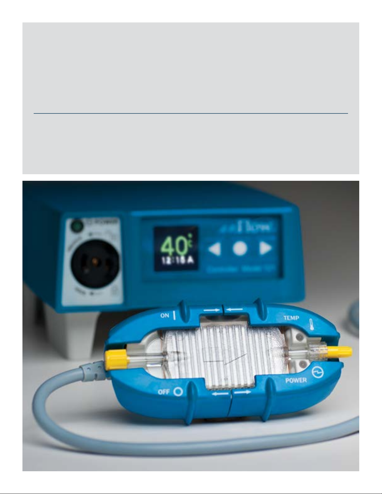
• The ‘High Priority Alarm’is a ashing RED LED, a ashing RED controller display, and an audible alarm, indicating that the infusate is over temperature.
Stop the uid ow, and slide the Warmer covers open to stop warming. If the above occurs, then replace the Warmer and contact Technical Support. The
attending practitioner should remain within 4 m of the patient when the device is in use to enable visualization of the enFlow display and hear the audible
high priority alarm.
• The Warmer contains magnets; do not operate within 15 cm (6 in) of a pacemaker or other devices that may be sensitive to strong magnetic elds.
• The Disposable Cartridge may be a potential biohazard during or after use. Handle and dispose of in accordance with acceptable medical practice and
applicable regulations.
• Do not use in the presence of ammable anesthetics.
• Replace the fuses with Bussmann®part #S500-5-R or equivalent.
• The Disposable Cartridge should not be used for more than 24 hours.
• Ensure that the Disposable Cartridge expiration date has not passed.
• If the IV line runs dry, disconnect the Disposable Cartridge from the Warmer. Re-prime the entire IV system using aseptic techniques. Ensure all the air is
removed from both the line and the Disposable Cartridge. Replace the Disposable Cartridge in the Warmer.
• The enFlow Warmer is to be used only with approved enFlow power sources and the enFlow Disposable Cartridge.
• To avoid risk of electric shock, this equipment must only be connected to a supply main that is grounded. Should the need arise the device may be
disconnected by the appliance coupler.
• Do not connect the enCheck®to an enFlow system while it is in any way connected to a patient.
Cautions
• Follow the AABB “Guidelines for the Use of Blood Warming Devices”(© 2006) which caution against warming when administering platelets,
cryoprecipitate, or granulocyte suspensions.
• Some drugs or drug preparations may be sensitive to warming. As with any uid or blood warming system, carefully review the drug manufacturer’s
literature for information about thermal sensitivity.
• The Disposable Cartridge contains aluminum. Review the preparation or solution manufacturer’s instructions for use about chemical sensitivity.
• Do not ax, place or bind the Warmer directly to a patient during general use.
• Do not wrap the Warmer in towels, sheets, blankets or drapes.
• Warmer Strap (980304VS30) may be used with the Warmer for transport purposes only, such as eld use (for the military) and inter-hospital transport and
ambulatory circumstances. Do not strap for non-transport scenarios.
• The Warmer heating surface and Disposable Cartridge can get quite warm when heating cold IV uids/blood at high ow rates. Wait a few seconds after
stopping the IV uid/blood ow before removing the Disposable Cartridge.
• The Controller should only be plugged into a hospital grade outlet.
• Do not block the fan in the Controller as this may cause overheating.
• Although the Warmer has been tested to insure it will survive a drop of 1 m (3.28 ft), care should be taken that the device is not dropped to reduce the
potential of damage.
• Do not clean with:
ketones (MEK, acetone, etc.) or
abrasive cleaners.
• Do not sterilize the Warmer with:
steam sterilization (autoclave) or
dry heat.
• Do not disinfect or sterilize the Controller.
• Do not spray or pour cleaning solutions directly on the Controller.
• Do not allow cleaning solutions to accumulate on the Controller.
• When using the Controller mounted to an IV pole, it must be tightly secured on the pole no higher than 122 cm (48 in) from the ground. The pole
should have a base diameter of no less than 61 cm (24 in). A Controller mounted too high on the IV pole may cause instability. IV pole accessories or the
attachment of uid bags may also cause instability.
• Normal wear and tear during use of the Warmer may cause the device to be susceptible to uid ingress. Carefully inspect the heating surface of the
Warmer for tears or foreign matter before each use and take out of service if necessary.
• Always secure the infusion set with the provided IV Line Clip on the Warmer power cable to prevent kinking in the line.
• Do not use a sti bristle brush or sharp probe to remove foreign material.
• Do not use compressed air to dry.

- 7 of 40 -
4400-0024-EN Rev A
• Avoid puncturing the heating surface. If damaged, remove the Warmer from service and replace immediately.
• This equipment is not intended for use in an oxygen rich environment (dened as >22% O2).
• No modication of this equipment is allowed.
• Do not position the device in a way that makes it dicult to disconnect the device.
• Due to highly stable components, microprocessor control, and built-in self-tests, an annual performance check is sucient.
• The steps listed in the enFlow IV uid/blood warming system operational checklist (Appendix F) should be performed at least once a year, or as required by
your accrediting body.
• The enCheck is to be used only with the enFlow Warmer and Controller.
• Do not touch the enCheck contact plate surface during or immediately after use since it may be very hot.
• The warmer and controller may be a potential biohazard during or after use. Handle and dispose of in accordance with acceptable medical practice and
applicable regulations at the end of their life.

- 8 of 40 -
4400-0024-EN Rev A
enFlow IV uid/blood warming system description
The enFlow IV uid/blood warming system consists of the enFlow Warmer (Model 100 series), the enFlow Controller (Model 121 series), the enFlow
Disposable Cartridge with IV extension set (Model 202) or without IV extension set (Model 200). Within seconds, this warming system delivers normothermic
infusate to the patient at ow rates of Keep Vein Open (KVO dened as 2 mL/min) to 200 mL/min when input uid temperature is 20 °C.
The Warmer is the reusable heating unit designed to work in conjunction with the Disposable Cartridge. Two multicolored light emitting diode (LED) indicators
on the Warmer indicate its power status and the uid/blood infusate temperature. The infusate within the Disposable Cartridge is warmed when in contact
with the heating surface of the Warmer. This surface is heated by means of electrical resistance. The Warmer contains redundant temperature sensors to help
ensure uid temperature accuracy and reliability. It also includes two independent over-heating protectors. Continuous internal diagnostics monitor essential
components and system parameters when heating uid/blood.
POWER
TEMP
OFF
ON
O
WE
R
TEMP
EMP
OFF
ON
P
O
F
ON
The Controller serves as a power supply for the Warmer unit. The Controller is designed to mount on an IV pole or sit on a table top. The front panel
includes a Controller reading in degrees Celsius, as well as a keypad, which controls the clock and the mute feature. The Controller display is always shown
right-side-up.
Controller Model 121
40°C
2:20 P
L
O
C
K
U
N
L
O
C
K
POWER
Each Disposable Cartridge and the Disposable Cartridge with IV extension set are radiation sterilized and non-pyrogenic, not made with natural rubber latex
or DEHP. The Disposable Cartridge connects to the IV extension set or any infusion set employing standard luer connectors. Once primed, the Disposable
Cartridge in conjunction with the Warmer and the Controller combine to complete the enFlow IV uid/blood warming system.
Indications for use
The enFlow IV uid/blood warming system’s intended use is for warming blood, blood products and intravenous solutions prior to administration. It is
designed to be used by healthcare professionals in hospital, clinical and eld environments to help prevent hypothermia.
Clinical and training information
Operators must be trained to set up and deliver blood/ IV solutions in a medically approved manner, including aseptic techniques and standard hospital
procedures. Use of the enFlow IV uid/blood warming system, when properly administered, will help to prevent hypothermia and the complications arising
therefrom.

- 9 of 40 -
4400-0024-EN Rev A
Unpacking the enFlow IV uid/blood warming system
Upon receipt of the enFlow IV uid/blood warming system components, visually inspect the shipping containers and internal contents for damage that may
have occurred during shipment. If there is any visible or mechanical damage to the contents, or if the order is incomplete, please contact Customer Service
immediately. The components for each model are reected below:
• Model 100
Warmer
Warmer Cord Clip
IV Line Clip
USB Manual
Patient Leakage Report
Certicate of Conformance
• Model 121
Controller
Patient Leakage Report
Warmer Mount (Warmer Mount Instructions)
USB Manual
• Model 200
Disposable Cartridge
IFU
Model 202
Disposable Cartridge with IV extension set
IFU
To begin operation of the enFlow IV uid/blood warming system
a. Place the Controller on a rm, level surface or on an IV pole with an outside dimension of no greater than 3.0 cm (1.25 in). Two Controllers may also be
mounted next to each other on an IV pole as shown below. The Controller’s display will have a right-side-up orientation regardless of its position.

- 10 of 40 -
4400-0024-EN Rev A
Controller Model 121
40°C
2:20 P
L
O
C
K
U
N
L
O
C
K
POWER
Controller Model 121
40°C
2:20 P
Controller Model 121
40°C
2:20 P
Controller Model 121
40°C
2:20 P
b. Plug the Controller into a hospital grade outlet.
c. Setting the clock to the local time is optional, but usually done on initial use. No changes in performance are aected by the clock’s setting.
(Please refer to the “enFlow Controller (Model 121 series) indicators and operations”section for directions to set the clock).
d. Connect the Warmer cable to the Controller. This action is accomplished in three steps:
1. Insert the male plug end of the Warmer into the female receptacle on the front face of the Controller. Push it in so that the plug cover is tight against
the receptacle.
enFl
o
2. The plug and receptacle are keyed in both orientation and conguration. This feature ensures that the Warmer can only be plugged in properly.
Additionally, it prevents other plug devices from tting into this receptacle.
3. Turn right to lock. (See arrows on label.)
e. The rear mounted I/0 (ON/OFF) switch on the Controller turns the power on and o. Switch the Controller to ON. Upon startup, the Controller conducts a
self-test. The power indicator illuminates green, the Controller display ashes “enFlow,”a short audible beep occurs, and the LED’s light up for about
one (1) second. Note : The Controller automatically switches for operation at either 100, 115, or 240 VAC (100-240 VAC).
POWER
TEMP
OFF
ON
f. Open the covers on the Warmer by sliding them apart.
g. Connect the infusion set and/or extension set to the Disposable Cartridge; then prime with uid using standard medically approved protocols. Next,
connect the infusion set to the patient and place the Disposable Cartridge into the Warmer.
POWER
OFF
TEMP
OFF
ON

- 11 of 40 -
4400-0024-EN Rev A
h. Completely close the covers on the Warmer by pressing down on the cartridge and sliding the covers inward toward each other until they meet. Upon
closing the covers, a short audible beep occurs indicating that the Warmer self-test is being performed and conrms operation of temperature sensors
and alarm indicators. After this process is complete, regulated power is delivered to the Warmer’s heating surface, which then begins heating the infusate
through the Disposable Cartridge. Adjust the uid ow to the desired rate.
POWER
TEMP
OFF
ON
i. Place the IV line in the IV Line Clip in order to prevent it from kinking.
ON
IV Line Clip
j. The Warmer is designed to be placed on the bed and/or attached to patient coverings in close proximity to the site of infusion using the cord clip
P/N 980309VS-20. Cushion the patient from the Warmer to aid in the prevention of perioperative peripheral neuropathies or heat-related dermal injury.
k. Do not wrap the Warmer in towels, sheets, blankets or drapes.
l. Opening the Warmer covers immediately stops the heating but not the ow.
m. To turn o the device, use the switch located at the rear of the Controller.

- 12 of 40 -
4400-0024-EN Rev A
enFlow Controller (Model 121 series) indicators and operation
Controller Model 121
40°C
2:20 P
Controller Display
Power Indicator
Female
Receptacle for
Warmer
Connector
Keypad
Controller (Model 121 series)—setup instructions
1. Set the clock
a. To modify the initial default mode of the Controller, press the center button of the front keys of the display window prior to pushing the power switch
that is located in the back of the unit. The key must be held down continuously until the clock is displayed.
b. Once the clock appears, toggle the center button to move through the elds. To change a eld, press the right or left arrow keys.
2. Set the Controller display default mode to symbols (International Mode)
a. Continue to toggle through to the set zone eld. Press either the right or left arrow key to access the padlock symbol to enter the password screen.
b. The password is 781.
c. An underscore will display under the rst digit eld. Press the arrow key to set the appropriate digit.
d. Next, press the center key again to toggle to the next place.
e. Repeat steps three and four for the second and third digits. If an incorrect password is entered, the system reverts to the set zone screen.
f. After the third digit is set, press the center key again. First a green padlock and then the zone USA will appear. Press the right arrow to change to INTL.
g. Press the center key again to set. The system begins to operate.
h. After the initial setup, whenever the Controller is powered on, the display screen defaults to the last mode entered.
Controller display
The Controller display continuously reects the specic infusate temperature that the Warmer monitors and maintains. The various readouts that may be
depicted on the Controller display are described in the following tables:

- 13 of 40 -
4400-0024-EN Rev A
Table 1—Controller Display: Normal Operating Model
Activity Display reads Display color and function
Warmer is connected and power is engaged. Temperature and Clock
40 °C
9:00 A
Identical to Warmer
temperature LED
Warmer is not connected, but Controller is powered on. Not Heating Yellow
Warmer is connected, but covers are open on Warmer. Not Heating Yellow
Warmer is connected, and covers are either open or
closed on Warmer; however, Cartridge is not in Warmer.
Not Heating Yellow
Table 2—Controller Display: Alarm Mode
Activity Display reads Display color and function
Warmer over temperature Display alternates between Over Temp and
Press Key to Mute
Identical to Warmer temperature LED
Mute button activated Over Temp Muted Identical to Warmer temperature LED
Fault detected System Fault XX
If a system fault message is on the Controller display,
refer to the system fault section
Appendix B or contact Technical Support.
Red
High priority alarm
Table 3—Controller Display: Setup Mode
Activity Display reads Display color and function
While powering up the Controller, hold the center button
down until the clock screen is displayed. Then, use the
buttons to set the clock.
09:00 A Blue
enFlow Warmer (Model 100 series) indicators and operation
The Warmer monitors and maintains the infusate temperature at 40 °C ± 2 °C. On the top of the Warmer, there are two status indicator lights (multicolored
LEDs), which reect the following:
Power - Indicates the power and operational status of the Warmer.
Temperature - Indicates that the infusate temperature is within an acceptable operating range (35 °C to 42 °C).
POWER
TEMP
OFF
ON
Power cable
Sliding covers
Heating surface
Temperature Status LED
(Indicated by symbol )
Power LED
(Indicated by symbol )

- 14 of 40 -
4400-0024-EN Rev A
Table 4: Warmer indicator status
Status Warmer
covers
Disposable
cartridge
Power LED
indicator
Temperature
LED indicator
Audible
indicator
Description Action required
Ready Open or closed None Flashing Green
every 3 seconds
Unlit None Warmer unit has power, but
is not heating
None
Device power up Closed In place Red
½ second
duration
Red
½ second
duration
½ second beep Successful device power
up and over temperature
circuit test
Observe. If the LED does
not ash red, replace the
Warmer; and contact
Technical Support.
In operation Closed In place Solid Green Flashing Blue None Infusate temperature is
< 33 °C
None
In operation Closed In place Solid Green Solid Blue None Infusate temperature is
≥ 33 °C and < 35 °C
None
In operation Closed In place Solid Green Solid or Flashing
Blue >30 seconds
None Warmer is unable to
heat the infusate within
operational range. Infusate
temperature is
< 20 °C and/or the ow
rate is > 200 mL/min.
Reduce the ow rate if
possible. If there is no
change in operational
temperature, consider
replacing the Warmer and
contact Technical Support.
In operation Closed In place Solid Green Solid Green None Infusate temperature is
≥35 °C and ≤ 42 °C
None
In operation Closed In place Solid Green Solid Yellow None Infusate (and/or ambient
temperature) is > 42 °C
but less than an Over Temp
condition
Observe. This state whereby
the infusate is > 42 ºC
should only be entered
periodically during changes
in ow rate or infusate
temperature.
In operation Closed In place Flashing Red N/A-Varies Continuous
audible bursts
Internal failure in the
Warmer
Replace the Warmer if this
occurs, and contact Technical
Support.
Continuous
operation
Closed In place Solid Green Flashing Red
High priority
alarm
Continuous
audible bursts
Infusate (and/or ambient
temperature) is > 45 °C
signifying an Over Temp
condition
Stop the uid ow, and slide
the Warmer covers open to
stop warming. Replace the
Warmer if this occurs, and
contact Technical Support.
Refer to Appendix C for the chart on “Warming system response by temperature.”
Refer to Warnings for additional information.
Cleaning the enFlow IV uid/blood warming system components
Caution
• Do not clean with:
Ketones (MEK, acetone, etc.)
Abrasive cleaners
• Do not sterilize the Warmer with:
Steam sterilization (autoclave)
Dry heat
• Do not disinfect or sterilize the Controller.
• Do not spray or pour cleaning solutions directly on the Controller.
• Do not allow cleaning solutions to accumulate on the Controller.

- 15 of 40 -
4400-0024-EN Rev A
The Warmer and Controller are chemically resistant to most common hospital grade instrument cleaning solutions and non-caustic detergents. The following
list of approved cleaning solutions may be used to clean the Warmer and Controller:
• 40% bleach sodium hypochlorite and 60% water solution
• Isopropyl alcohol
• Clorox®Bleach Germicidal Wipe
• Cidex®OPA
• CIDEX®Glut
• CaviWipes®
• Super Sani-Cloth®
• Sani-Cloth®HB
• Sani-Cloth®AF
Cleaning the Warmer
Wipe down and/or wash
1. After each use, clean the Warmer only as required. In many instances, it may only need to be wiped clean.
2. If the Warmer needs to be cleaned more intensively, use a cleaning solution and a soft bristle brush to gently scrub the Warmer to remove any foreign
material.
3. Be sure to wipe clean the orange heating surface regularly. If the heating surface starts to grey or if the controller displays a system fault 50, thoroughly
clean with isopropyl alcohol and inspect for damage to the heating surface.
4. Rinse thoroughly with distilled water. Do not immerse the Warmer’s electrical plug connector.
Drying
1. After cleaning, dry completely before placing back into use.
2. If disinfecting is required, dry completely before disinfecting so that the disinfecting solution will not be diluted.
Disinfecting
1. The enFlow Warmer may be disinfected using commercially available solutions with no greater than 2.4% glutaraldehyde and by following the solution
manufacturer’s recommendations. (Refer to list in Cleaning Section, above.)
2. Soak the Warmer in the disinfectant solution according to the manufacturer’s application time guidelines. Do not immerse the Warmer’s electrical plug
connector in the solution.
3. Thoroughly rinse the Warmer of all solution using distilled water.
4. Completely dry the Warmer before placing into service.
5. Conrm operation. Connect the Warmer to a Controller. Insert a Disposable Cartridge into the Warmer and close the covers. Turn the Controller to the
ON position, and allow the start up procedure to run until complete.
Cleaning the Controller
1. Use only approved cleaning solutions.
2. Moisten a clean cloth with the cleaning solution; do not spray or pour cleaning solutions directly on to the Controller.
3. Wipe the surface of the Controller, taking care not to leave excess residual cleaner on the Controller. If uid ingress is detected, set the Controller aside for
an extended period of time to allow it to dry.
Storing the enFlow IV uid/blood warming system components
The Warmer and Controller should be stored in a clean, dust free environment. (See Appendix A)

- 16 of 40 -
4400-0024-EN Rev A
Servicing the enFlow IV uid/blood warming system components
The enFlow IV uid/blood warming system components have been designed to be durable and long lasting. The system uses current Surface Mount
Technology (SMT) and materials. If a System Fault error occurs, then remove the device from service and refer to the table in Appendix B for proper evaluation
and handling. Do not return the device or place it back into service unless it has been cleaned per the instructions above and evaluated by a trained technician
using the instructions in Appendix E and Appendix F. If the unit stops working properly, contact Customer Service to obtain an Return Goods Authorization
(RGA) number prior to returning the unit to Vital Signs. If damage has occurred to the heating surface, immediately remove it from service.
RGA number
The Technical Support Representative will troubleshoot your product issue with you on the phone. If it is necessary to return a product under warranty, a
replacement unit will be shipped to you within 48 hours. (If the product is no longer under warranty, the Customer Advocacy Representative will discuss
replacement options.) You will be issued a RGA number. You will be instructed to return the product in sucient packaging to prevent damage in transit,
clearly marking the RGA number on the outside of the box. The return address will be provided to you.
Warmer (Model 100 series)
The Warmer is permanently sealed against uid ingress and has no user serviceable parts inside.
Controller (Model 121 series)
See “Servicing the enFlow IV uid/blood warming system components”below for information on user serviceable parts inside the Controller. Check the fuses
located in the outside power entry module if the Controller fails to function. The power cord must be removed to do this.
Replaceable parts for the Controller:
• Clock battery (See below for replacement instructions)
• Fuse – Bussmann #S500-5-R or equivalent (See below for replacement instructions)
• Cover
• Screws
• Pole clamp screw
• Power cord
• Warmer mount
The Controller should be subjected to routine safety checks as required by local regulations, (i.e., Earthing Impedance, Leakage Current).
Instructions for replacing the Controller clock battery
Clock Battery Specications
Cell # CR2032
Classication Lithium Coin
Chemical System Lithium / Manganese Dioxide (Li/MnO2)
Designation ANSI / NEDA-5004LC, IEC-CR2032
Nominal Voltage 3.0 Volts
Typical Capacity 220 mAh

- 17 of 40 -
4400-0024-EN Rev A
1. Turn Controller over.
Diagram 1 Diagram 2
Controller Model 121
L
O
C
K
U
N
L
O
C
K
Controller Model 121
L
O
C
K
U
N
L
O
C
K
2. To remove the bottom, unscrew pole clamp screw; unscrew six (6) screws shown below. Next, lift the cover.
Diagram 3 Diagram 4
Screw_1
Screw_5 Screw_6
Screw_3 Screw_4
Screw_2
Pole Clamp Screw
3. Remove power supply assembly
a. On the power supply assembly, unscrew two (2) screws shown below (see Diagram 5). Also remove the screws holding the zip ties to the post for the
ferrite bead securement.
b. Gently lift assembly by holding pole clamp, and prop up with a small block or box (see Diagram 6).
Diagram 5 Diagram 6
Screw_1
Pole Clamp
Zip ties
Screw_2
Display
Board
Battery
Post_1 Post_2
Fan Assembly
Display Board
Block
White Posts
Pole Clamp

- 18 of 40 -
4400-0024-EN Rev A
4. Remove display panel
a. On the display panel, remove the four (4) screws at the end of the panel next to the display screen (see Diagram 7).
b. Pull the display panel away from the fan assembly.
c. With pliers, gently pull out battery.
d. Insert new battery in the same direction as the old battery. Push rmly into place.
e. Reinsert and tighten all screws on the display board.
Diagram 7
enFlow
Controller Model 121
POWER
U
N
L
O
C
K
L
O
C
K
Display
Remove
Screw_1
Remove
Screw_3
Battery
Remove
Screw_4
Remove
Screw_2
Block or Box
5. Reassembly
a. Reseat fan assembly and display board (see Diagram 5).
b. When reseating display board, make sure that all wires are between the two white posts (see Diagram 6).
c. When reseating the fan assembly on the display board end, make sure that the wires are inside the corner post_1 (See Diagram 5) and wrap around
the edge of the fan assembly.
d. On the opposite end from the display board, make sure the wires go around the outside of the corner post_2.
e. Reinsert and tighten the two (2) screws for the power assembly (see Diagram 5).
f. Reinstall the two screws for the zip ties that were taken apart in step 3a.
g. Attach bottom cover; reinsert and tighten the six (6) related cover screws (see Diagram 3).
h. Reinsert pole clamp screw.
i. Dispose of the old battery in accordance with any government regulations in eect in your area.
Instructions for changing the Controller fuse
Note : Remove power cord before inserting screwdriver.
1. Insert a screwdriver on either side of the fuse box and push gently to pop the fuse case out of its socket.
Fuses
Fuse Case Keyed
2. Pull the fuse out of the case.
3. Replace the fuse with (Bussmann #S500-5-R or equivalent). The socket in the Controller is keyed so that the fuse case can only be inserted in the correct
orientation. Push the case in gently, but rmly, until it snaps into place. At this point, it will be ush with the surrounding surface.

- 19 of 40 -
4400-0024-EN Rev A
enFlow uid warming system temperature control and alarms
Temperature control
The enFlow IV uid/blood warming system includes multiple safety features to prevent overheating of infusion uids. There are built-in redundancies and
back-up safety systems as means for protection in the event of a failure in the primary control mechanism. Several aspects of the system work together to
accomplish desired and appropriate safety:
1. Closed-loop temperature control software
2. Audible and visual alarms
3. Software system monitor
4. Independent heater temperature monitoring circuit
Audible/Visual alarms
The enFlow system incorporates an audible/visual alarm system. This system monitors the uid temperature for an over-temperature condition and system
faults. The alarm function is tested each time a Cartridge is inserted. The audible alarm is briey sounded, and the red light emitting diode indicator is also
briey illuminated. If a dangerous condition occurs, a continuous audible and visual alarm is activated. Over-temperature conditions are calculated according
to ASTM Standard F2172-02 (an FDA recognized standard for uid warmers). This standard allows for spikes in the uid temperature without activating an
alarm. The alarm has a linear time-temperature relationship; therefore, the hotter the uid the less time it will take for the alarm to be activated. At 45 ºC
the alarm will sound after about 20 seconds while at 50 ºC it will be essentially instantaneous. The alarm will be activated by either the Warmer over-heating
the uid or if the uid entering the Warmer is too hot. The audible aspect of the alarm can be muted for 1 minute by pressing any key on the Controller. The
alarm can also be ended completely by sliding open the covers on the Warmer. (For further information, please reference test for Over-temperature Alarm
located in Appendix E: Preventive Maintenance Procedure.)
enFlow troubleshooting
Electromagnetic interference
• ECG, EEG or EMG (cardiac or neuro monitoring) artifact or other interference caused by the enFlow is an uncommon event.
• Cardiac or neuro monitoring interference is common and well-documented in medical literature.
• There are published suggestions to reduce or eliminate the interference that should be employed.
“Interference of the monitored or recorded electrocardiogram is common within operating room and intensive care unit environments.”1The enFlow
IV uid/blood warming system, as with all electrical devices, can be associated with some electromagnetic interference (EMI); however, it has been uncommon
and inconsistently experienced. Below are troubleshooting suggestions for situations where interference is observed:
Interference conrmation
Turn the unit o. Turn the power supply on the back of the Controller to the OFF position. Reassess the interference. Knowing that cardiac or neuro
monitoring is being aected, determine if the interference adversely aects your ability to care for the patient. Consider attempting to reduce the level of
interference by employing some simple and readily available solutions.
Interference reduction steps
Check the monitoring pads
All monitoring pads should be fully adhered to the patient’s properly prepared skin. Conrm that the pad’s foam insulator is not curled up, peeled back
or otherwise exposing the conductive gel layer. Conrm that the leadwires’connectors are properly and fully attached. Consider reapplying monitoring
electrodes if there is any suspicion they have dried out.
Conrm the patient is properly grounded
In many cases, and in all cases using mono-polar or bi-phase cautery, a grounding pad should be present and applied according to the manufacturer’s
instructions. As previously suggested, conrm the ground pad is fully adhered to a properly prepared skin surface.
1Patel, Santosh I., M.D., F.R.C.A. and Souter, Michael J, M.B., Ch.B., F.R.C.A.; Equipment-related Electrocardiographic Artifacts, Causes, Characteristics,
Consequences, and Correction; Anesthesiology 2008; 108:138–48.

- 20 of 40 -
4400-0024-EN Rev A
Conrm the enFlow and the ECG monitor are plugged into dierent outlets
There are two reasons for this action. It is possible that the two systems are in an electrical phase related conict, which is being expressed on the monitor.
Secondly, it is possible that the outlets are not properly grounded or grounded in dierent locations. While rare, it can be the case and outwardly there would
be no way to tell.
Conrm the Warmer cord is not entwined or near the ECG lead cable
Separating the two cords will allow each cable’s shielding to work to its full potential.
Conrm the monitoring cables and lead wires are in proper working order
The insulating layer on lead wires and cables degrades over time and with use. Conrm the insulation is intact and operates at its stated specications.
Review the monitor’s notch lter
Check to ensure that the monitoring system’s frequency lter is set appropriately.
Determine the monitor’s sensitivity setting
Many physiological monitors have the ability to interpret electrical signals in two distinct modes: a highly sensitive “Diagnostic” mode or a more ltered
“Monitoring”mode. Determine the current mode of operation. If the current mode is set on“Diagnostic” consider adjusting it to “Monitoring.”
Check the ECG pads impedance
Contact your current supplier of monitoring pads or your local Vital Signs representative to determine if a lower impedance version is available. High
impedance monitoring pads are less sensitive to the very low signal strength from the heart beat and appear to be more prone to pronounced interference.
enCheck (Model 400) user guide
Intended use
Use this product only for the purpose for which it was designed; refer to product description below.
Purpose
The enCheck tester was developed to quickly and reliably trigger the over-temperature alarm condition on the enFlow Warmer. Within seconds, the enCheck
unit will heat the Warmer to an over- temperature scenario causing the alarm to sound. Additionally, the enCheck is designed to verify the Warmer operation
at enFlow’s installation site.
Procedure
When the enCheck is connected and running in the normal mode, the heat is generated from the Warmer unit using the same technology as when a
cartridge is installed. This mode allows for conrmation of the temperature output of the Warmer. (See Appendix E, section on“Simulated Use Performance
Testing.”)
enCheck system description
The enCheck is designed to verify the Warmer operation at enFlow’s installation site. In the Normal Mode, it allows for conrmation of the temperature
output of the Warmer. In the Overheat Mode, it heats the Warmer to an over-temperature scenario causing the alarm to sound.
Other manuals for enFlow IV
1
Table of contents
Other GE Medical Equipment manuals
Popular Medical Equipment manuals by other brands

AMT
AMT Bridle Standard Directions, Indications, & Contraindications For Use

Otto Bock
Otto Bock Genium Protector 4X880 Series Instructions for use

Mediblink
Mediblink M600 Instructions for use

Inventec Appliances
Inventec Appliances Chiline S68 instruction manual

Basic American
Basic American ZENITH Series Instructions for use and service manual

Gima
Gima 27500 user manual