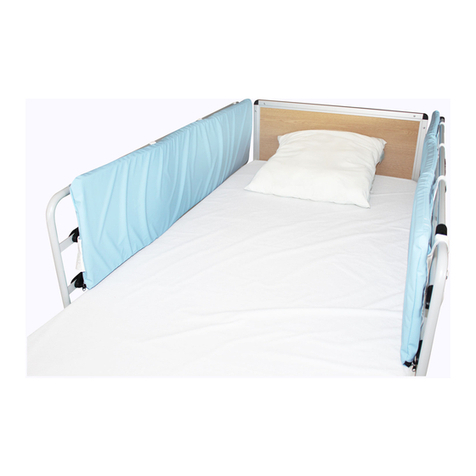
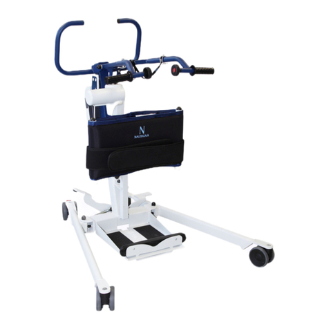
NAUSICAA CONVERTISS FOLDING PREMIUM User manual

v01.10/19
CONVERTISS FOLDING PREMIUM
NAUSICAA Médical est certifiée ISO 13485
www.nausicaa-medical.com
User Manual / CONVERTISS FOLDING PREMIUM
Made by NAUSICAA Medical S.A.S. / Approved by Ghizlane Labrosse (Biomedical Engineer)
MANUFACTURING STEEL
MAXIMUM PATIENT WEIGHT : 180 kg
CLASS 1 MEDICAL DEVICE
ALL OUR DEVICES COMPLY WITH NF EN ISO 60601-2-52: 2010

User Manual / CONVERTISS FOLDING PREMIUM
Made by NAUSICAA Medical S.A.S. / Approved by Ghizlane Labrosse (Biomedical Engineer)
1. HEAD PANEL
2. METAL 4-BAR BED RAILS (not shown)
3. HAND CONTROL
4. BED RAIL RELEASE LEVER
5. FOOT PANEL
6. WHEELS WITH BRAKE
7. HOUSING FOR LIFTING POLE (ON BOTH SIDES)
4
5
2
1
36
7

User Manual / CONVERTISS FOLDING PREMIUM
Made by NAUSICAA Medical S.A.S. / Approved by Ghizlane Labrosse (Biomedical Engineer) 1
INDEX
INTRODUCTION
2. GENERAL INFORMATION
2.1 Groups of people mentioned in this manual
2.2 Safety warnings
2.2.1Safety symbols used
2.2.2 Safety warnings for the owner
2.2.3 Safety instructions for the user
2.3 Product description
2.3.1 Proper use
2.3.2 Special features
2.3.3 Materials used
2.3.4 Frame
3. ASSEMBLY AND OPERATIONS
3.1 Assembly
3.1.1 Use of accessories
3.2 Operations
3.2.1 Requirements of the installation site
3.2.2 Operations
4. FUNCTIONING
4.1 Special safety warnings
4.2 Hand control
4.2.1 Hand control use
4.3 Swivel wheels
4.4 Lifting Pole
4.5 Bed Lever
4.6 Dynamic Mattress
4.7 Bed Rails
4.8 Bed End Panels
5. CLEANING AND DISINFECTING
5.1 General information
5.2 Cleaning and disinfection program
5.3 Training of users
5.4 Detergents and disinfectants
5.4.1How to use disinfectants
6. MAINTENANCE
6.1 By the user
6.2 By the owner
6.3 Spare parts
6.4 Electrical components replacement
7. ELIMINATING DEFECTS
8. TECHNICAL DATA
8.1 Size and weight
8.2 Electrical data
8.3 Environmental conditions
9. LABELLING
10. WARRANTY
p.2
p.3
p.3
p.3
p.3
p.4
p.4
p.5
p.5
p.5
p.5
p.5
p.6
p.6
p.8
p.8
p.8
p.8
p.9
p.9
p.9
p.9
p.10
p.10
p.11
p.11
p.11
p.12
p.13
p.13
p.13
p.13
p.14
p.14
p.14
p.14
p.16
p.19
p.19
p.20
p.21
p.21
p.21
p.21
p.22
p.23

2
User Manual / CONVERTISS FOLDING PREMIUM
Made by NAUSICAA Medical S.A.S. / Approved by Ghizlane Labrosse (Biomedical Engineer)
1. INTRODUCTION
Dear customer,
NAUSICAA Médical wishes to thank you for purchasing one of our nursing beds
and for the trust shown in our products.
The electrical safety and functionality of each bed has been extensively tested
by the manufacturer in order to avoid any faults.
This manual provides useful information to the buyer and to the end user on all
the functions which will allow a safe and practical daily use of this bed.
Therefore, we recommend you to use this manual as a handy guide and to keep
it near your bed.
In the hope that for you and for the users of this nursing bed to succeed, we are
confident that our product will greatly contribute to achieving this goal.
CONVERTISS

2. GENERAL INFORMATION
Before using the bed:
•Read through this whole manual in order to avoid causing damages to the bed due to improper use.
Before using the nursing bed, the user must verify its perfect status and complete efficiency.
This bed conforms to all the requirements of Directive 93/42/EEC for medical products and it is classified as a Class I
medical device.
This manual contains safety instructions which must be fully respected. All the people involved with using the bed
must know the complete contents of this manual and observe the safety warnings listed herein.
Information for the owner:
• Every electrical appliance may cause hazards if used incorrectly. Therefore it is necessary to instruct the user on how
to use the nursing bed correctly.
• Inform the user of where this manual will be kept.
2.1 GROUPS OF PEOPLE MENTIONED IN THIS MANUAL
The manual may refer to the following groups of people somehow involved with using the bed:
• Owner
The owner (for example: suppliers of medical products, dealers, health care authorities, etc.) can be any physical person
or juridical body which uses the nursing bed or under whose name the bed is being used. The owner is responsible for
providing the necessary information to the user.
• User
the user is the person authorized to use the nursing bed and to carry out any operations on the bed on the basis of his/
her training, experience or education, and who has been trained to use the bed. Furthermore, the user must be able to
recognize and avoid potential hazards and evaluate the condition of the patient.
• Patient
In this manual the term patient refers to the person who needs to be taken care of, who might be sick or disabled and
therefore in need of using this bed.
• Specialized personnel
The term specialized personnel refers to the owner’s co-operators who are authorized, on the basis of their training or
education, to deliver and assemble.
2.2 SAFETY WARNINGS
5
2. GENERAL INFORMATION
Before using the bed:
•Read through this whole manual in order to avoid causing damagesto
the bed due to improper use.
Before using the nursing bed, the user must verify its perfect functional status and complete
efficiency.This bed conforms to all the requirements of Directive 93/42/EEC for medical
products and it is classified as a Class I medical device.
This manual contains safety instructions which must be fully respected. All the people
involved with using the bed must know the complete contents of this manual and observe
the safety warnings listed herein.
Information for the owner:
•Every electrical appliance may cause hazards if used incorrectly. Therefore,it is
necessary to instruct the user on how to use the nursing bed correctly.
•Inform the user of where this manual will be kept.
2.1 Groups of people mentioned in this manual
Themanual may refer to the following groups of people that are involved with installing,
inspecting using, testing or repairing the bed:
•Owner
The owner (for example: suppliers of medical products, dealers, health care
authorities, etc.) can be any physical person or judical body which uses the nursing
bed or under whose name the bed is being used. The owner is responsible for
providing the necessary information to the user.
•User
the user is the person authorised to use the nursing bed and to carry out any
operations on the bed on the basis of his/her training, experience or education, and
who has been trained to use the bed. Furthermore, the user must be able to perform
basic safety checks on the bed, and also be able to recognise and avoid potential
hazards, as well as evaluating the condition of the patient.
•Patient
In this manual the term patient refers to the person who needs to be taken care of,
who might be sick or disabled and therefore in need of using this bed.
•Specialised personnel
The term specialised personnel refers to the ownersown technicians or personnel
from the owners appointed company who are authorised,on the basis of their
training or education, to deliver and assemble the bed.
The nursing bed is a high technology product, therefore make sure to read the complete manual when delivered. Make
sure to use the nursing bed only if it is in good condition.
The goal of the safety warnings is to avoid injuries to people.
2.2.1 SAFETY SYMBOLS USED
The following symbols appear in this manual:
Warnings against injuries
This symbol indicates the presence of dangerous power voltage which could jeopardize the user’s life.
This symbol indicates the presence of hazards which might jeopardize the user’s life and cause health problems.
Warnings against damages to property
This symbol indicates a potential damage to things or properties. Damages to the bed mechanism, to its materials
or to the environment might occur.
6
2.2 Safety warnings
The nursing bed is a high technology product therefore,all relevant personnel should read
the complete manual whenthe bed is delivered.Make sure to use the nursing bed only if it
is in agood and fully functioning condition. The aim of the safety warnings are to avoid
injuries to the user or the patient.
2.2.1 Safety symbols used
The following symbols appear in this manual:
Warnings against injuries
This symbol indicates the presence of dangerous power voltage which could
jeopardise the user’s life.
This symbol indicates the presence of hazards which might jeopardise the
user’s life or cause health problems.
Warningsagainst damages to property
This symbol indicates a potential damage to things or properties. Damagesto
the bed mechanism,to its materialsor to the environment might occur.
Other warnings
This symbol indicates a general useful suggestion. Following this suggestion, it
will be easier to use the bed and to understand the instructions.
The safety symbol used does not replace the safety text it refers to.
It is always necessary to read the relevant safety warning in full and to follow it carefully!
2.2.2 Safety warnings for the owner
•Before the bed is used, inform the user about safely operating the bed by strictly following
the information and warnings contained in this manual, which must be provided together
with the bed. Inform each user of any possible dangers due to anyimproper use. Pay
special attention when using the electric functions and the bed rails.
•Nursing beds are classified as active Class I medical devices. You must fulfil your
obligations in accordance with the current regulations about installation, operation and
use of medical devices, to ensure a safe and durable useof this medical product without
any risks for patients, users and any third parties. In case of a prolonged use of the bed,
it is necessary to carry out an inspection, after a certain period of time (we recommend
at least every year),to check its functionality and any visible damages(see Chapter 6).
3
User Manual / CONVERTISS FOLDING PREMIUM
Made by NAUSICAA Medical S.A.S. / Approved by Ghizlane Labrosse (Biomedical Engineer)

User Manual / CONVERTISS FOLDING PREMIUM
Made by NAUSICAA Medical S.A.S. / Approved by Ghizlane Labrosse (Biomedical Engineer)
Other warnings
This symbol indicates a general useful suggestion. Following this suggestion, it will be easier to use the bed
and to understand the instructions.
The safety symbol used does not replace the safety text it refers to.
It is always necessary to read the relevant safety warning in full and to follow it carefully!
2.2.2 SAFETY WARNINGS FOR THE OWNER
• Before the bed is used, inform the user about safely operating the bed by strictly following this manual which must be
provided together with the bed. Inform each user of any possible dangers due to any improper use. Pay special attention
when using the electric functions and the bed rails.
• Nursing beds are classified as active Class I medical devices. You must fulfil your obligations in accordance with the cur-
rent regulations about installation, operation and use of medical devices, to ensure a safe and durable use of this medical
product without any risks for patients, users and any third parties. In case of a prolonged use of the bed, it is necessary to
carry out an inspection, after a certain period of time (we recommend at least every year), to check its functionality and
any visible damages (see Chapter 6).
• Make sure that only qualified personnel use this bed.
• Make sure that any possible substitute personnel are also sufficiently trained on how to use the bed correctly.
• In case any additional electric accessories are used such as air compressors for overlay mattresses, make sure they are
properly installed and work correctly. In particular pay attention to the following:
➢- Make sure all cables, flexible tubes etc are fixed correctly.
- Do not use a multiple socket under the bed (possible fire hazard in case of contact with liquids). If in doubt, please contact
the manufacturer of the accessories.
• Make sure all staff complies with the safety warnings.
2.2.3 SAFETY INSTRUCTIONS FOR THE USER
Make sure to be instructed on the safe use of the bed by the owner.
• Before each use check the good condition and the absence of defects in the nursing bed.
• Make sure there are no obstructions such as furniture or inclinations of the ceiling when making any adjustments.
• In case any additional electric components are also used such as hoists, reading lamps or air compressors for overlay
mattresses, make sure their cable does not get caught in the mobile parts of the bed or get damaged.
• Multiple sockets must not be used for connecting any external electrical components.
• If you suspect damage or malfunctioning, immediately disconnect the power plug from the wall, clearly mark it as
“Damaged” and deactivate the nursing bed. Immediately inform the owner of the bed about this situation. In chapter 6.1
you will find a checklist to assess the condition of the bed.
5
2. GENERAL INFORMATION
Before using the bed:
•Read through this whole manual in order to avoid causing damagesto
the bed due to improper use.
Before using the nursing bed, the user must verify its perfect functional status and complete
efficiency.This bed conforms to all the requirements of Directive 93/42/EEC for medical
products and it is classified as a Class I medical device.
This manual contains safety instructions which must be fully respected. All the people
involved with using the bed must know the complete contents of this manual and observe
the safety warnings listed herein.
Information for the owner:
•Every electrical appliance may cause hazards if used incorrectly. Therefore,it is
necessary to instruct the user on how to use the nursing bed correctly.
•Inform the user of where this manual will be kept.
2.1 Groups of people mentioned in this manual
Themanual may refer to the following groups of people that are involved with installing,
inspecting using, testing or repairing the bed:
•Owner
The owner (for example: suppliers of medical products, dealers, health care
authorities, etc.) can be any physical person or judical body which uses the nursing
bed or under whose name the bed is being used. The owner is responsible for
providing the necessary information to the user.
•User
the user is the person authorised to use the nursing bed and to carry out any
operations on the bed on the basis of his/her training, experience or education, and
who has been trained to use the bed. Furthermore, the user must be able to perform
basic safety checks on the bed, and also be able to recognise and avoid potential
hazards, as well as evaluating the condition of the patient.
•Patient
In this manual the term patient refers to the person who needs to be taken care of,
who might be sick or disabled and therefore in need of using this bed.
•Specialised personnel
The term specialised personnel refers to the ownersown technicians or personnel
from the owners appointed company who are authorised,on the basis of their
training or education, to deliver and assemble the bed.
2. GENERAL INFORMATION
Safety warnings for the userr
•The power cord must be installed so that when operating the bed it is not carried away, crushed or damaged by
any moving parts.
•Before transport totally remove the plug from the socket.
•When the bed is not used, make sure there is no possibility for the hand control to fall and get damaged (it must remain
attached to the hook). Make sure the cable cannot be damaged by any moving parts of the nursing bed.
• Place the bed in the lowest position when you leave the patient unattended on the bed. In so doing, the risk of injuries
to the patient when getting on and off the bed is minimized.
• The adjustments can be made only by trained personnel or in the presence of experienced staff.
• Check the power cord regularly for possible mechanical damages (abrasions, uncovered wires, bends, dents, etc…)
especially in the following cases:
• after each mechanical overload (for example: crushing of the cable with the bed itself or with a trolley, after strong trac-
tions and bending of the bed with the power cord plugged in)
• after each change of position/after every movement before inserting the plug
• during the normal operation by the user
• Regularly check that the power cord assembly is properly tightened.
7
•Make sure that only qualified personnel use this bed.
•Make sure that any possible substitute personnel are also sufficiently trained on how to
use the bed correctly and safely.
•In case any additional electric accessories are used such as air compressors for overlay
mattresses,make sure they are properly installed and work correctly. In particular pay
attention to the following:
Make sure all cables, flexible tubes etc.are fixed correctly.
Do not use a multiple socket under the bed (possible fire hazard in case of contact
with liquids). If in doubt,please contact the manufacturer of the accessories.
•Make sure all relevant staff are aware and fully complywith the safety warnings.
2.2.3 Safety instructions for the user
•Make sure the user is instructed on the safe use of the bed by the owner.
•Before each use check the good condition and the absence of defects in the nursing
bed.
•Make sure there are no obstructions such as furniture or inclinations of the ceiling before
and during making any bed position adjustments.
•In case any additional electric components are also used such as hoists, reading lamps
or air compressors for overlay mattresses, make sure their cable is not able to get caught
in the mobile parts of the bed or get damaged.
•Multiple sockets must not be used for connecting any external electrical components.
•If you suspect damage or any malfunction, immediately disconnect the power plug from
the wall, clearly mark it as “Damaged” and deactivate the nursing bed. Immediately
inform the owner of the bed about this situation. In chapter 6.1 you will find a checklist to
assess the condition of the bed.
Safety warnings for the user
•The power cord must be installed so that when operating the bed it cannot
be disconnected, crushed or damaged by any of the moving parts of the bed.
•Before transport you must remove the electric power plug from the socket.
•When the bed is not used, make sure there is no possibility for the hand control
to fall and become damaged (it must remain attached to the hook). Make sure the cable
cannot be damaged by any moving parts of the nursing bed.
•Place the bed in the lowest position when you leave the patient unattended on the bed.
In so doing, the risk of injuries to the patient when getting on and off the bed is minimised.
•The adjustments can be made only by trained personnel or in the presence of
experienced staff.
•Check the power cord regularly for possible mechanical damages (abrasions, uncovered
wires, bends, dents, etc.)
•Regularly check that the power cord assembly is properly tightened.
4

User Manual / CONVERTISS FOLDING PREMIUM
Made by NAUSICAA Medical S.A.S. / Approved by Ghizlane Labrosse (Biomedical Engineer) 5
2. GENERAL INFORMATION
2.3 PRODUCT DESCRIPTION
2.3.1 PROPER USE
• The nursing bed, hereinafter simply called “bed”, is designed for disabled or ill people and is suitable also for home care.
• The bed was not specifically designed for hospital use.
• This bed can be used for treatment with a doctor’s prescription and it can be used for diagnosis, care or observation of
the patient.
• This bed does not have any special options suitable for an equipotential connection.
Make sure to take this aspect into account before connecting with any other (medical) equipment already linked to the
power supply.
• This bed must be used only by adequately trained people.
• This bed is designed for repeated re-use. Please follow the instructions listed below:
➢ Cleaning and disinfecting (see chapter 5)
➢ Maintenance / Verification of tests (see chapter 6.2)
This bed can be used only according to the use conditions described in this manual. Any other use is not to be consi-
dered as proper.
2.3.2 FEATURES
• Electric height adjustment of the bed surface from 31 to 71 cm.
• Electric backrest section adjustment from 0° to 72°.
• Electric leg section adjustment from 0° to 33°.
• Four swivel wheels, individually lockable.
• Hospital surface 208 x 88 cm.
• Overall dimensions about 225 x 105.
• Option of full length 4 Bar Metal bed rails on both sides.
2.3.3 MATERIALS USED
The bed is mostly made up by steel tubing profiles, covered by a polyester powder coating or by a metallic zinc or chrome
coating. The head/foot panels are made of wood or similar material, whose surface is waterproof.
The surfaces are not harmful in contact with the skin.
2.3.4 FRAME
The bed is supplied part assembled to be easily transported into the house. It is made up of the bed frame with wooden
panel inserts (head panel and foot panel), a mattress base with a motor, a pantograph mechanism with an electric actuator,
two four-bar metal bed rails and one lifting pole with grab bar (accessory NOT included with the bed). The bed has four
swivel wheels, all with a parking brake.
• Mattress base
The mattress base is divided into a backrest with a fixed central element, a leg support and a knee raiser with ratchet.
These elements are adjustable. The foot or head parts of the mattress base can be adjusted in height horizontally or obli-
quely compared to the floor. All the adjustments are performed by electric motors by using a hand control.
• Bed Rails
To protect patients from possible accidental falls from the bed, the bed can be equipped with rails (meet clause
201.9.8.3.3.3 of IEC 60601-2-52) on both sides, which can act as a barrier or be lowered when not in use. The blocking
mechanism is locked and it can be released only by pulling the lever out on the side (see No. 4 on Page 2)
• Electric system
The electric operating system of this bed is safe and easy to use. It consists of:
• Electronic controller. A minimum protection voltage of 24 volts is produced which is not dangerous for the patient and
the user. The electric motors and the hand control are connected to the central controller with connectors, which work
with a minimum protection voltage of 24 volts.
• Separate electric motors for the back and the leg supports.
• Two electric motors to adjust the height of the mattress base (one in each bed end).
• A hand control unit with fixed hook.

6
User Manual / CONVERTISS FOLDING PREMIUM
Made by NAUSICAA Medical S.A.S. / Approved by Ghizlane Labrosse (Biomedical Engineer)
• The bed is supplied part assembled.
• The bed is assembled on location by the retailer’s personnel.
• The installation must be carried out by a minimum of one person.
Packaging units:
Carton:
Complete bed frame consisting of the mattress platform and head and foot end panels. Main control unit, hand control,
back & foot rest actuators and 2 height adjusting actuators.
3.1 ASSEMBLY
Mounting instructions:
• The assembly of the bed must be carried out by a minimum of one person;
Unpack the bed frame from carton 1 and make sure that the 2 wheels on the foot-
board are in the locked position and the 2 wheels on the headboard are unlocked.
Unhook the transport securing arm to let the bed begin to unfold. To do so you will need to manually push the 2 halves
of the folded bed together a little so that the hook can move free from the pin
The buttons on the handset that control the angle of the back rest also control the folding and unfolding of the bed.
By pressing the button to lower the back rest it will unfold the bed automatically until it is in the flat position.
Once the bed frame is in the flat position and the backrest actuator has ceased moving, the bed is ready to be used.
3. ASSEMBLY AND OPERATION
Never attempt to unfold the bed a u t o m a t i c a l l y b e f o r e unhooking the transport securing
arm.
11
The main control box comes already attached to the
knee break actuator with all the cables for the
actuators and the handset connected.
The knee break actuator should be mounted under
the bed frame so that the motor end (the end where
the cables connects to the actuator) is towards the
centre of the bed and the extending ram of the
actuator is connected to the moving knee break
section of the mattress platform.
In order to insert the securing pin into the end of the
extending ram you need to manually lift the knee
break and pull out the ram so that it is away from the
control box it is attached to, allowing you to insert the
locking pin. Please see image to the left.
The backrest actuator should then be mounted under the bed frame again so that the
motor end is towards the centre of the bed and the extending ram is connected to the
moving back rest section of the mattress platform.
Ensure all mounting pins are fully inserted through the bed frame mounting points on both
sides of the actuator and the spring loaded locking loops are in the closed position.
All the cables should be already attached to the control box and numbered 1 –4 with a
tag on the opposite end where they connect into each actuator. The number inside the
control box (re circles above) should correspond with the same number on the other end
of each cable.
Number 1 cable should be connected into the backrest actuator.
Number 2 cable should be connected into Hi-Lo actuator at the foot end of the bed.
Number 3 cable should be connected into the backrest actuator.
Number 4 cable should be connected into the Hi-Lo actuator at the head end of the bed.
Pay attention to position the back and foot rest actuators correctly!They should
never be inverted.
1
2.3.4CHASSIS
•
Systeme electrique
Ajouterces2photosendessousdutexte
3. ASSEMBLAGE ET FONCTIONNEMENT
3.1 Assemblage
Instructions de montage:
• Le montage du lit doit être effectué par au moins une personne.
Déballez le cadre du lit du carton 1 et assurez-vousnt déverrouillées.
Décrochezlatôledeverrouillagepourpermettreaulitdecommenceràsedéplier.Pourcefaire,
vousdevrezrapprocherunpeulesdeuxmoitiésdulitpliéafinquelecrochetpuissesedégager
delagoupille.
2
Lesboutonsdelatélécommandequicontrôlentl’angledudossiercontrôlentégalementlepliage
etledéploiementdulit.
Enappuyantsurleboutonpourbaisserledossier,lelitsedéplieautomatiquementjusqu'àce
qu'ilsoitàplat.
Ne jamais essayer de déplier le lit automatiquement avant décrochage de la tôle de
verrouillage.
Une fois que le cadre du lit est à plat et que le vérin du dossier a cessé de bouger, le lit est prêt à
être utilisé.
14
In such a rare case,increase the distance of the bed from the interfering device,do not
use the same socket or temporarily disconnect such device.
4.2 Hand control
The electric functions of the bed are activated by the patient and by the user with ahand
control.
•The electric motors work if the corresponding buttons are pressed.
•It is possible to adjust different sections in both directions.
•The hand control can be attached to the bed where needed with a hook.
•The spiral cable allows freedom of movement.
•Individual functions of the bed can be locked using the hand control.
4.2.1 Hand control use
Backrest adjustment
When the bed is in use these buttonsare used to change the angle of
the backrest.
Leg support adjustment
When the bed is in use these buttonsare used to change the angle of
the leg support (knee break).
Backrest and leg support combined adjustment (Auto-Contour)
When the bed is in use these buttons are used to change the angle of
the backrest and the angle of the leg support simultaneously.
Height adjustment of the mattress base
When the bed is in use these buttons are used to change the height of
the mattress base. When the height is adjusted there is an automatic
horizontal positioning of the mattress base in the highest/lowest position.
Angle adjustment of feet –head section (Trendelenburg Tilt)
When the bed is in use these buttons can be used to lower the foot or
head section independently. When the height is adjusted there is an
automatic horizontal adjustment of the mattress base if lowered at the
feet in the highest position and/or in the lowest one.
Before lowering either section, you need to release the brake of the two wheels on the head
or foot panel end,to avoid possible damagesto the floor.
Trendelenburg Tilt -is when the foot end is raised higher than the head end. This is
apotentially dangerous position for some patients. Trendelenburg Tilt should only
be used if appropriate medical advice has been obtained or if you are sure this
position is safe for the patient.
Nurse Lock-Out –Each pair of buttons on the handset can be individually locked out to
prevent unwanted operation. Using the blue key provided with the handset you can turn
the central lock to either UNLOCKED (12 o’clock position) or LOCKED (1 o’clock position).

7
User Manual / CONVERTISS FOLDING PREMIUM
Made by NAUSICAA Medical S.A.S. / Approved by Ghizlane Labrosse (Biomedical Engineer)
3. ASSEMBLY AND OPERATION
Located at the head of the bed, on the backrest
platform is the red hook illustrated in the images
to the left.
In order to raise the backrest you must unhook
the clip from the pin and push it down as shown.
This will then enable the backrest actuator to operate the mattress platform rather than folding the bed back up. The leg
rest actuator and the two height adjusting actuators on the head and foot boards are already connected to the central
control box. These can now be operated using the hand control.
To fold the bed back up ensure that the mattress platform is flat (backrest and leg rest lowered fully) and in its lowest
position. Then swing the clip back into the locked position.
This will disengage the backrest actuator for operating the mattress platform and engage the folding mechanism.
Making sure that the wheels on the footboard are both locked and the wheels on the headboard are both unlocked, press
the button on the handset to raise the backrest and the bed will begin to fold up.
Before folding the bed back up make sure that the mattress platform, including the leg rest, is completely
flat and that the bed is in the lowest position.
Never attempt to use any other functions on the bed when in the folded position. Only the backrest but-
tons to either fold or unfold the bed. Only use the other functions when the bed is completely unfolded
and flat.
3
Situéàlatêtedulit,surlerelèvebuste,setrouvelecrochetrougeillustrédanslesimagesà
gauche.
Pourreleverledossier,vousdevezdécrocherleclipdelagoupilleetlepoussercommeindiqué.
Celapermettraensuiteauvérindurelèvebustedefairefonctionnerledossierplutôtquede
replierlelitenarrière.Levérinderepose-jambesetlesdeuxvérinsderéglagedehauteur
situéssurlespanneauxdetêteetdepiedsontdéjàconnectésauboîtierdecommandecentral.
Ceux-cipeuventmaintenantêtreutilisésàl'aidedelatélécommande.
Pourreplierlelit,assurez-vousquelesommierestplat(relèvebusteetrepose-jambes
complètementabaissé)etdanssapositionlaplusbasse.Remettezensuiteleclipdansla
positionverrouillée.Celadésengageralevérindurelèvebustepouractionnerledossieret
engageralemécanismedepliage.
Pourvousassurerquelesroulettesdupieddelitsonttouteslesdeuxbloquéesetqueles
roulettesdelatêtedelitsonttouteslesdeuxdéverrouillées,appuyezsurleboutondela
télécommandepourreleverledossieretlelitcommenceraàsereplier.
Avantdereplierlelit,assurez-vousquelesommier,ycomprislerepose-jambes,est
complètementplatetquelelitestdanslapositionlaplusbasse.
N'essayezjamaisd'utiliserd'autresfonctionssurlelitlorsquevousêtesenpositionpliée.Seuls
lesboutonsdudossierpermettentdeplieroudedéplierlelit.Utilisezlesautresfonctions
uniquementlorsquelelitestcomplètementdépliéetàplat.
Assurez-vousdenepasendommagerlescâbles.Vérifiezquelescâblesnesontpasemmêléset
qu’ilsnesecoincentpasdanslespiècesmobiles.
Encasderemplacementdecomposantsindividuels,assurez-voustoujoursquelesfiches
électriquessontcorrectementinséréesdanslecontrôleur.Seulementdecettefaçon,lelit
fonctionneracorrectement
11
The main control box comes already attached to the
knee break actuator with all the cables for the
actuators and the handset connected.
The knee break actuator should be mounted under
the bed frame so that the motor end (the end where
the cables connects to the actuator) is towards the
centre of the bed and the extending ram of the
actuator is connected to the moving knee break
section of the mattress platform.
In order to insert the securing pin into the end of the
extending ram you need to manually lift the knee
break and pull out the ram so that it is away from the
control box it is attached to, allowing you to insert the
locking pin. Please see image to the left.
The backrest actuator should then be mounted under the bed frame again so that the
motor end is towards the centre of the bed and the extending ram is connected to the
moving back rest section of the mattress platform.
Ensure all mounting pins are fully inserted through the bed frame mounting points on both
sides of the actuator and the spring loaded locking loops are in the closed position.
All the cables should be already attached to the control box and numbered 1 –4 with a
tag on the opposite end where they connect into each actuator. The number inside the
control box (re circles above) should correspond with the same number on the other end
of each cable.
Number 1 cable should be connected into the backrest actuator.
Number 2 cable should be connected into Hi-Lo actuator at the foot end of the bed.
Number 3 cable should be connected into the backrest actuator.
Number 4 cable should be connected into the Hi-Lo actuator at the head end of the bed.
Pay attention to position the back and foot rest actuators correctly!They should
never be inverted.
12
Make sure not to damage any cables. Verify that the cables are not tangled
and that theyare not able to get caught in any in moving parts during use.
In case of replacement of any individual components, always make sure that
the electric plugsare then properly inserted into the controller.Only in this way
will the bed function properly.
3.1.1 Use of accessories
Apollo Healthcare Technologies can supply various accessories for use with this bed
including a lifting pole, bed lever and dynamic mattress systems. For correct installation of
accessories please refer to section 4of this manual.
Use of non-Apollo Healthcare Technologies accessories is not advised.Installing
third party accessories could restrict the moving parts of the bed.The warranty
does not cover any damages caused by use of third party accessories and your
warranty could be void if third party accessories are installed and used.
3.2 Operations
Every time before using the bed, the user must make sure that:
•the wheels of the bed are locked (see also chapter 4.3).
•the power supply is compatible with the bed (230 Volt, 50 Hertz).
•the power cable is plugged in and placed in such a way that it cannot be damaged.
•the power cable,the motor cables and the hand control cable are not damaged by
any moving parts of the nursing bed.
•there are no obstacles in the way such as bedside furniture or chairs.
•all accessories used are installed correctly and do not restrict the free movement of any
part of the bed especially the backrest and knee break mattress platform.
•all control functions have been accurately inspected (see also chapter 6.1) and are
working properly.
•only after carrying out the above operations should the bed be regarded as safe to use.
3.2.1 Requirements of the installation site
•Make sure there is enough space to safely allow the whole range of adjustments of the
bed. There should not be any furniture or other objects close to the bed such as window
cills.
•If the bed is to be used on parquet floor, make sure that the use of wheels will not cause
any discolouring due to the parquet waterproof treatment. It is possible to use the bed
on tiles, carpets, laminatedfloorsand linoleum.
•A 230 volt power outlet,correctly installed, must be located as near as possible to the
bed.
•If there is the need to use other accessories (such as compressor systems,bed levers
etc…), make sure they are correctly fixed and that they work properly. In particular, make
sure all different cables are safely connected and no moving part of the bed is restricted
from moving freely as it should.In case of questions or doubts please contact the
manufacturer of such accessories.
Make sure not to damage any cables. Verify that the cables do not get tangled and that they do not get
caught in any in moving parts.
In case of replacement of any individual components, always make sure that the electric plugs are then
properly inserted into the controller. Only in this way the bed will function properly.

3.1.1 USE OF ACCESSORIES
NAUSICAA Médical can supply various accessories for use with this bed including side rails, lifting pole, bed lever and
dynamic mattress systems. For correct installation of accessories please refer to section 4 of this manual.
Use of non-NAUSICAA Médical accessories is not advised. Installing third party accessories could
restrict the moving parts of the bed. The warranty does not cover any damages caused by use of third party
accessories and your warranty could be void if third party accessories are installed and used.
3.2 OPERATIONS
Every time before using the bed, the user must make sure that:
• the wheels of the bed are locked (see also chapter 4.3).
• the power supply is compatible with the bed (230 Volt, 50 Hertz).
• the power cable is plugged in and placed in such a way that it cannot be damaged.
• the power cable, the motor cables and the hand control cable are not damaged by any moving parts of the nursing bed.
• there are no obstacles in the way such as bedsides or chairs.
• any accessories are installed correctly and do not restrict the free movement of any part of the bed especially the back-
rest and knee break mattress platform.
• all control functions have been accurately inspected (see also chapter 6.1) and are working properly.
• only after having carried out the above operations it will be possible to start using the bed.
3.2.1 REQUIREMENTS OF THE INSTALLATION SITE
• Make sure there is enough space to allow the whole range of adjustments of the bed. There should not be any furniture
or other objects close to the bed such as window cills.
• If the bed is to be used on parquet floor, make sure that the use of wheels will not cause any discolouring due to the
parquet waterproof treatment. It is possible to use the bed on tiles, carpets, laminated floors and linoleum.
• A 230 volt power outlet, correctly installed, must be located as near as possible to the bed.
• If there is the need to use other accessories (such as compressor systems, bed levers etc…), make sure they are correctly
fixed and that they work properly. In particular, make sure all different cables are safely connected and no moving part
of the bed is restricted from moving freely as it should. In case of questions or doubts please contact the manufacturer
of such accessories.
During the installation of the bed you must take the following issues into serious consideration to minimize
potential fire hazards due to external influences. Inform the user and the personnel about these issues!•
• If possible, use only non-flammable mattresses and linens.
• Don’t smoke while in bed as there is no guarantee against risks caused by smoking tools (such as lighters, matches)
depending on the mattresses and linens used.
• Use any electric accessories (electric blanket) and appliances (lights, radios) only if they are in a good condition.
• Make sure these appliances are used only for their intended purpose and that they cannot accidentally end up on and
under the sheets (risk of overheating).
• Absolutely avoid using extension cables or connections to multiple sockets under the bed (fire hazard due to the pene-
tration of liquids).
• Extension cables and/or power multiple sockets should never be used at all.
3.2.2 OPERATIONS
• After the assembly of the bed, make sure to carry out an inspection in conformity with chapter 6.2.
After carrying out all the instructions listed in chapters 3.1 3.2.2 the bed can Start functioning.
8
User Manual / CONVERTISS FOLDING PREMIUM
Made by NAUSICAA Medical S.A.S. / Approved by Ghizlane Labrosse (Biomedical Engineer)
3. ASSEMBLY AND OPERATION
12
Make sure not to damage any cables. Verify that the cables are not tangled
and that theyare not able to get caught in any in moving parts during use.
In case of replacement of any individual components, always make sure that
the electric plugsare then properly inserted into the controller.Only in this way
will the bed function properly.
3.1.1 Use of accessories
Apollo Healthcare Technologies can supply various accessories for use with this bed
including a lifting pole, bed lever and dynamic mattress systems. For correct installation of
accessories please refer to section 4of this manual.
Use of non-Apollo Healthcare Technologies accessories is not advised.Installing
third party accessories could restrict the moving parts of the bed.The warranty
does not cover any damages caused by use of third party accessories and your
warranty could be void if third party accessories are installed and used.
3.2 Operations
Every time before using the bed, the user must make sure that:
•the wheels of the bed are locked (see also chapter 4.3).
•the power supply is compatible with the bed (230 Volt, 50 Hertz).
•the power cable is plugged in and placed in such a way that it cannot be damaged.
•the power cable,the motor cables and the hand control cable are not damaged by
any moving parts of the nursing bed.
•there are no obstacles in the way such as bedside furniture or chairs.
•all accessories used are installed correctly and do not restrict the free movement of any
part of the bed especially the backrest and knee break mattress platform.
•all control functions have been accurately inspected (see also chapter 6.1) and are
working properly.
•only after carrying out the above operations should the bed be regarded as safe to use.
3.2.1 Requirements of the installation site
•Make sure there is enough space to safely allow the whole range of adjustments of the
bed. There should not be any furniture or other objects close to the bed such as window
cills.
•If the bed is to be used on parquet floor, make sure that the use of wheels will not cause
any discolouring due to the parquet waterproof treatment. It is possible to use the bed
on tiles, carpets, laminatedfloorsand linoleum.
•A 230 volt power outlet,correctly installed, must be located as near as possible to the
bed.
•If there is the need to use other accessories (such as compressor systems,bed levers
etc…), make sure they are correctly fixed and that they work properly. In particular, make
sure all different cables are safely connected and no moving part of the bed is restricted
from moving freely as it should.In case of questions or doubts please contact the
manufacturer of such accessories.
13
During the installation of the bed you must take the following issues into serious
consideration to minimise potential fire hazards due to external influences. Inform
the user and the personnel about these issues!
•If possible, use only non-flammable mattresses and linens.
•Don’t smoke while in bed as there is no guarantee against risks caused by smoking tools
(such as lighters, matches) depending on the mattresses and linens used.
•Use any electric accessories (electric blanket) and appliances (lights, radios) only if they
are in a good condition.
•Make sure these appliances are used only for their intended purpose and that they
cannot accidentally end up on and under the sheets (risk of overheating).
•Absolutely avoid using extension cables or connections to multiple sockets under the
bed (fire hazard due to the penetration of liquids).
•Extension cables and/or power multiple sockets should never be used under any
circumstances.
3.2.2 Operations
•After the assembly of the bed, make sure to carry out a complete inspection in
conformity with chapter 6.2.
After carrying out all the instructions listed in chapters 3.1 3.2.2 the bed can start
functioning.
4. FUNCTIONING
4.1 Special safety warnings
•When making the adjustments make sure that no parts of the body of any
patients, users and other people, especially children, are positioned under any
adjustable elements or under the bed frame to avoid being caught and injured.
•Once you have made the necessary adjustments and positioned the bed rails correctly,
make sure to disable the backrest and leg adjustmentsfunctions with the hand control
lock, to protect the patient from unwanted movements (risk of crushing of his/her limbs).
•In case of use of accessories on the electric bed, make sure such accessories do not
crush or cut the patient with sharp edges during the legs and backrest adjustments. If
this condition is not guaranteed, the user must not proceed with the backrest and legs
adjustments.
•Make sure the power cable and the hand control cable do not get caught anywhere or
get damaged.
•Before each operation with the bed, make sure the power cable is not
stretched, crushed or damaged in any way.
•When making the adjustments, make sure there are no obstructions such as
furniture or aceiling inclination, to avoid possible damages.
As with all electrical appliances, despite the compliance with prescribed
values, it is not possible to totally exclude the possibility of interferencesfrom
other electrical devices which might be nearby (for ex. the “buzz” of aradio).
Ensure all accessories are fully removed from the bed before attempting to fold the bed back up
into the storage/transport position.
11
The main control box comes already attached to the
knee break actuator with all the cables for the
actuators and the handset connected.
The knee break actuator should be mounted under
the bed frame so that the motor end (the end where
the cables connects to the actuator) is towards the
centre of the bed and the extending ram of the
actuator is connected to the moving knee break
section of the mattress platform.
In order to insert the securing pin into the end of the
extending ram you need to manually lift the knee
break and pull out the ram so that it is away from the
control box it is attached to, allowing you to insert the
locking pin. Please see image to the left.
The backrest actuator should then be mounted under the bed frame again so that the
motor end is towards the centre of the bed and the extending ram is connected to the
moving back rest section of the mattress platform.
Ensure all mounting pins are fully inserted through the bed frame mounting points on both
sides of the actuator and the spring loaded locking loops are in the closed position.
All the cables should be already attached to the control box and numbered 1 –4 with a
tag on the opposite end where they connect into each actuator. The number inside the
control box (re circles above) should correspond with the same number on the other end
of each cable.
Number 1 cable should be connected into the backrest actuator.
Number 2 cable should be connected into Hi-Lo actuator at the foot end of the bed.
Number 3 cable should be connected into the backrest actuator.
Number 4 cable should be connected into the Hi-Lo actuator at the head end of the bed.
Pay attention to position the back and foot rest actuators correctly!They should
never be inverted.

User Manual / CONVERTISS FOLDING PREMIUM
Made by NAUSICAA Medical S.A.S. / Approved by Ghizlane Labrosse (Biomedical Engineer)
4. FUNCTIONING
4.1 SPECIAL SAFETY WARNINGS
11
The main control box comes already attached to the
knee break actuator with all the cables for the
actuators and the handset connected.
The knee break actuator should be mounted under
the bed frame so that the motor end (the end where
the cables connects to the actuator) is towards the
centre of the bed and the extending ram of the
actuator is connected to the moving knee break
section of the mattress platform.
In order to insert the securing pin into the end of the
extending ram you need to manually lift the knee
break and pull out the ram so that it is away from the
control box it is attached to, allowing you to insert the
locking pin. Please see image to the left.
The backrest actuator should then be mounted under the bed frame again so that the
motor end is towards the centre of the bed and the extending ram is connected to the
moving back rest section of the mattress platform.
Ensure all mounting pins are fully inserted through the bed frame mounting points on both
sides of the actuator and the spring loaded locking loops are in the closed position.
All the cables should be already attached to the control box and numbered 1 –4 with a
tag on the opposite end where they connect into each actuator. The number inside the
control box (re circles above) should correspond with the same number on the other end
of each cable.
Number 1 cable should be connected into the backrest actuator.
Number 2 cable should be connected into Hi-Lo actuator at the foot end of the bed.
Number 3 cable should be connected into the backrest actuator.
Number 4 cable should be connected into the Hi-Lo actuator at the head end of the bed.
Pay attention to position the back and foot rest actuators correctly!They should
never be inverted.
•When making the adjustments make sure that no parts of the body of any patients, users and other
people, especially children, are positioned under any adjustable elements or under the bed frame to avoid
being caught and injured.
•Once you have made the necessary adjustments and positioned the bed rails correctly, make sure to lock
the backrest and leg adjustments possibilities with the hand control, to protect the patient from unwanted
movements (risk of crushing of his/her limbs).
• In case of use of accessories on the electric bed, make sure such accessories do not crush or cut the
patient with sharp edges during the legs and backrest adjustments. If this condition is not guaranteed, the
user must not proceed with the backrest and legs adjustments.
• Make sure the power cable and the hand control cable do not get caught anywhere or get damaged.
4.2 HAND CONTROL
The electric functions of the bed are activated by the patient and by the user with a hand control.
• The electric motors work if the corresponding buttons are pressed.
• It is possible to adjust different sections in both directions.
• The hand control can be attached to the bed where needed with a hook.
• The spiral cable allows freedom of movement.
4.2.1 HAND CONTROL USE
•Before each operation with the bed, make sure the power cable is not stretched, crushed or damaged in
any way.
•When making the adjustments, make sure there are no obstructions such as furniture or a ceiling inclination,
to avoid possible damages.
As with all electrical appliances, despite the compliance with prescribed values, it is not possible to totally
exclude the possibility of interferences from other electrical devices which might be nearby (for ex. the “buzz”
of a radio). In such a rare case, increase the distance of the bed from the interfering device, do not use the
same socket or temporarily disconnect such device.
Backrest adjustment / Folding & Unfolding the Bed
When the bed is in use these buttons are used to change the angle of the backrest. These
buttons are also used to fold and unfold the bed (see Section 3.1 Assembly on page 10 of
this manual for further details)
Leg support adjustment
When the bed is in use these buttons are used to change the angle of the leg support (knee
break).
Backrest and leg support combined adjustment (Auto-Contour)
When the bed is in use these buttons are used to change the angle of the backrest and the
angle of the leg support simultaneously.
12
Make sure not to damage any cables. Verify that the cables are not tangled
and that theyare not able to get caught in any in moving parts during use.
In case of replacement of any individual components, always make sure that
the electric plugsare then properly inserted into the controller.Only in this way
will the bed function properly.
3.1.1 Use of accessories
Apollo Healthcare Technologies can supply various accessories for use with this bed
including a lifting pole, bed lever and dynamic mattress systems. For correct installation of
accessories please refer to section 4of this manual.
Use of non-Apollo Healthcare Technologies accessories is not advised.Installing
third party accessories could restrict the moving parts of the bed.The warranty
does not cover any damages caused by use of third party accessories and your
warranty could be void if third party accessories are installed and used.
3.2 Operations
Every time before using the bed, the user must make sure that:
•the wheels of the bed are locked (see also chapter 4.3).
•the power supply is compatible with the bed (230 Volt, 50 Hertz).
•the power cable is plugged in and placed in such a way that it cannot be damaged.
•the power cable,the motor cables and the hand control cable are not damaged by
any moving parts of the nursing bed.
•there are no obstacles in the way such as bedside furniture or chairs.
•all accessories used are installed correctly and do not restrict the free movement of any
part of the bed especially the backrest and knee break mattress platform.
•all control functions have been accurately inspected (see also chapter 6.1) and are
working properly.
•only after carrying out the above operations should the bed be regarded as safe to use.
3.2.1 Requirements of the installation site
•Make sure there is enough space to safely allow the whole range of adjustments of the
bed. There should not be any furniture or other objects close to the bed such as window
cills.
•If the bed is to be used on parquet floor, make sure that the use of wheels will not cause
any discolouring due to the parquet waterproof treatment. It is possible to use the bed
on tiles, carpets, laminatedfloorsand linoleum.
•A 230 volt power outlet,correctly installed, must be located as near as possible to the
bed.
•If there is the need to use other accessories (such as compressor systems,bed levers
etc…), make sure they are correctly fixed and that they work properly. In particular, make
sure all different cables are safely connected and no moving part of the bed is restricted
from moving freely as it should.In case of questions or doubts please contact the
manufacturer of such accessories.
5
2. GENERAL INFORMATION
Before using the bed:
•Read through this whole manual in order to avoid causing damagesto
the bed due to improper use.
Before using the nursing bed, the user must verify its perfect functional status and complete
efficiency.This bed conforms to all the requirements of Directive 93/42/EEC for medical
products and it is classified as a Class I medical device.
This manual contains safety instructions which must be fully respected. All the people
involved with using the bed must know the complete contents of this manual and observe
the safety warnings listed herein.
Information for the owner:
•Every electrical appliance may cause hazards if used incorrectly. Therefore,it is
necessary to instruct the user on how to use the nursing bed correctly.
•Inform the user of where this manual will be kept.
2.1 Groups of people mentioned in this manual
Themanual may refer to the following groups of people that are involved with installing,
inspecting using, testing or repairing the bed:
•Owner
The owner (for example: suppliers of medical products, dealers, health care
authorities, etc.) can be any physical person or judical body which uses the nursing
bed or under whose name the bed is being used. The owner is responsible for
providing the necessary information to the user.
•User
the user is the person authorised to use the nursing bed and to carry out any
operations on the bed on the basis of his/her training, experience or education, and
who has been trained to use the bed. Furthermore, the user must be able to perform
basic safety checks on the bed, and also be able to recognise and avoid potential
hazards, as well as evaluating the condition of the patient.
•Patient
In this manual the term patient refers to the person who needs to be taken care of,
who might be sick or disabled and therefore in need of using this bed.
•Specialised personnel
The term specialised personnel refers to the ownersown technicians or personnel
from the owners appointed company who are authorised,on the basis of their
training or education, to deliver and assemble the bed.
14
In such a rare case,increase the distance of the bed from the interfering device,do not
use the same socket or temporarily disconnect such device.
4.2 Hand control
The electric functions of the bed are activated by the patient and by the user with ahand
control.
•The electric motors work if the corresponding buttons are pressed.
•It is possible to adjust different sections in both directions.
•The hand control can be attached to the bed where needed with a hook.
•The spiral cable allows freedom of movement.
•Individual functions of the bed can be locked using the hand control.
4.2.1 Hand control use
Backrest adjustment
When the bed is in use these buttonsare used to change the angle of
the backrest.
Leg support adjustment
When the bed is in use these buttonsare used to change the angle of
the leg support (knee break).
Backrest and leg support combined adjustment (Auto-Contour)
When the bed is in use these buttons are used to change the angle of
the backrest and the angle of the leg support simultaneously.
Height adjustment of the mattress base
When the bed is in use these buttons are used to change the height of
the mattress base. When the height is adjusted there is an automatic
horizontal positioning of the mattress base in the highest/lowest position.
Angle adjustment of feet –head section (Trendelenburg Tilt)
When the bed is in use these buttons can be used to lower the foot or
head section independently. When the height is adjusted there is an
automatic horizontal adjustment of the mattress base if lowered at the
feet in the highest position and/or in the lowest one.
Before lowering either section, you need to release the brake of the two wheels on the head
or foot panel end,to avoid possible damagesto the floor.
Trendelenburg Tilt -is when the foot end is raised higher than the head end. This is
apotentially dangerous position for some patients. Trendelenburg Tilt should only
be used if appropriate medical advice has been obtained or if you are sure this
position is safe for the patient.
Nurse Lock-Out –Each pair of buttons on the handset can be individually locked out to
prevent unwanted operation. Using the blue key provided with the handset you can turn
the central lock to either UNLOCKED (12 o’clock position) or LOCKED (1 o’clock position).
9

User Manual / CONVERTISS FOLDING PREMIUM
Made by NAUSICAA Medical S.A.S. / Approved by Ghizlane Labrosse (Biomedical Engineer)
4.3 SWIVEL WHEELS
11
The main control box comes already attached to the
knee break actuator with all the cables for the
actuators and the handset connected.
The knee break actuator should be mounted under
the bed frame so that the motor end (the end where
the cables connects to the actuator) is towards the
centre of the bed and the extending ram of the
actuator is connected to the moving knee break
section of the mattress platform.
In order to insert the securing pin into the end of the
extending ram you need to manually lift the knee
break and pull out the ram so that it is away from the
control box it is attached to, allowing you to insert the
locking pin. Please see image to the left.
The backrest actuator should then be mounted under the bed frame again so that the
motor end is towards the centre of the bed and the extending ram is connected to the
moving back rest section of the mattress platform.
Ensure all mounting pins are fully inserted through the bed frame mounting points on both
sides of the actuator and the spring loaded locking loops are in the closed position.
All the cables should be already attached to the control box and numbered 1 –4 with a
tag on the opposite end where they connect into each actuator. The number inside the
control box (re circles above) should correspond with the same number on the other end
of each cable.
Number 1 cable should be connected into the backrest actuator.
Number 2 cable should be connected into Hi-Lo actuator at the foot end of the bed.
Number 3 cable should be connected into the backrest actuator.
Number 4 cable should be connected into the Hi-Lo actuator at the head end of the bed.
Pay attention to position the back and foot rest actuators correctly!They should
never be inverted.
4.4 LIFTING POLE (ADDITIONAL ACCESSORY)
In both corners of the mattress base, towards the head panel, there is a round insert with a cavity into which the lifting
pole must be placed. The lifting pole must be inserted in the side from where the patient gets in or out of the bed to help
him/her out.
Assembly
Place the lifting pole into its housing. The metal pin must be placed into the cavity. Make sure to double check the oscil-
lation field of the lifting pole which must be limited.
Disassembly
• Remove the lifting pole from its housing by pulling it upwards.
Height adjustment of the mattress base
When the bed is in use these buttons are used to change the height of the mattress base.
When the height is adjusted there is an automatic horizontal positioning of the mattress base
in the highest/lowest position.
Angle adjustment of feet – head section (Trendelenburg Tilt)
When the bed is in use these buttons can be used to lower the foot or head section inde-
pendently. When the height is adjusted there is an automatic horizontal adjustment of the
mattress base if lowered at the feet in the highest position and/or in the lowest one.
Before lowering either section, you need to release the brake of the two wheels on the head
or foot panel side, to avoid possible damages to the floor.
Nurse Lock-Out - Each pair of buttons on the handset can be individually locked out to prevent unwanted operation.
Using the blue key provided with the handset you can turn the central lock to either UNLOCKED (12 o’clock position) or
LOCKED (1 o’clock position).
Trendelenburg Tilt - is when the foot end is raised higher than the head end. This is a potentially dange-
rous position for some patients. Trendelenburg Tilt should only be used if appropriate medical advice
has been obtained or if you are sure this position is safe for the patient.
•Bring the mattress base into its lowest position.
•Before each operation of the bed, make sure the power cable is not stretched, crushed or damaged in
any way.
How to apply the brake: Press the lower lever down with your foot until it clicks.
12
Make sure not to damage any cables. Verify that the cables are not tangled
and that theyare not able to get caught in any in moving parts during use.
In case of replacement of any individual components, always make sure that
the electric plugsare then properly inserted into the controller.Only in this way
will the bed function properly.
3.1.1 Use of accessories
Apollo Healthcare Technologies can supply various accessories for use with this bed
including a lifting pole, bed lever and dynamic mattress systems. For correct installation of
accessories please refer to section 4of this manual.
Use of non-Apollo Healthcare Technologies accessories is not advised.Installing
third party accessories could restrict the moving parts of the bed.The warranty
does not cover any damages caused by use of third party accessories and your
warranty could be void if third party accessories are installed and used.
3.2 Operations
Every time before using the bed, the user must make sure that:
•the wheels of the bed are locked (see also chapter 4.3).
•the power supply is compatible with the bed (230 Volt, 50 Hertz).
•the power cable is plugged in and placed in such a way that it cannot be damaged.
•the power cable,the motor cables and the hand control cable are not damaged by
any moving parts of the nursing bed.
•there are no obstacles in the way such as bedside furniture or chairs.
•all accessories used are installed correctly and do not restrict the free movement of any
part of the bed especially the backrest and knee break mattress platform.
•all control functions have been accurately inspected (see also chapter 6.1) and are
working properly.
•only after carrying out the above operations should the bed be regarded as safe to use.
3.2.1 Requirements of the installation site
•Make sure there is enough space to safely allow the whole range of adjustments of the
bed. There should not be any furniture or other objects close to the bed such as window
cills.
•If the bed is to be used on parquet floor, make sure that the use of wheels will not cause
any discolouring due to the parquet waterproof treatment. It is possible to use the bed
on tiles, carpets, laminatedfloorsand linoleum.
•A 230 volt power outlet,correctly installed, must be located as near as possible to the
bed.
•If there is the need to use other accessories (such as compressor systems,bed levers
etc…), make sure they are correctly fixed and that they work properly. In particular, make
sure all different cables are safely connected and no moving part of the bed is restricted
from moving freely as it should.In case of questions or doubts please contact the
manufacturer of such accessories.
14
In such a rare case,increase the distance of the bed from the interfering device,do not
use the same socket or temporarily disconnect such device.
4.2 Hand control
The electric functions of the bed are activated by the patient and by the user with ahand
control.
•The electric motors work if the corresponding buttons are pressed.
•It is possible to adjust different sections in both directions.
•The hand control can be attached to the bed where needed with a hook.
•The spiral cable allows freedom of movement.
•Individual functions of the bed can be locked using the hand control.
4.2.1 Hand control use
Backrest adjustment
When the bed is in use these buttonsare used to change the angle of
the backrest.
Leg support adjustment
When the bed is in use these buttonsare used to change the angle of
the leg support (knee break).
Backrest and leg support combined adjustment (Auto-Contour)
When the bed is in use these buttons are used to change the angle of
the backrest and the angle of the leg support simultaneously.
Height adjustment of the mattress base
When the bed is in use these buttons are used to change the height of
the mattress base. When the height is adjusted there is an automatic
horizontal positioning of the mattress base in the highest/lowest position.
Angle adjustment of feet –head section (Trendelenburg Tilt)
When the bed is in use these buttons can be used to lower the foot or
head section independently. When the height is adjusted there is an
automatic horizontal adjustment of the mattress base if lowered at the
feet in the highest position and/or in the lowest one.
Before lowering either section, you need to release the brake of the two wheels on the head
or foot panel end,to avoid possible damagesto the floor.
Trendelenburg Tilt -is when the foot end is raised higher than the head end. This is
apotentially dangerous position for some patients. Trendelenburg Tilt should only
be used if appropriate medical advice has been obtained or if you are sure this
position is safe for the patient.
Nurse Lock-Out –Each pair of buttons on the handset can be individually locked out to
prevent unwanted operation. Using the blue key provided with the handset you can turn
the central lock to either UNLOCKED (12 o’clock position) or LOCKED (1 o’clock position).
5
4.2Commandemanuelle
Lesfonctionsélectriquesdulitsontactivéesparlepatientetparl'utilisateuràl'aided'une
commandemanuelle.
•Lesvérinsélectriquesfonctionnentsilesboutonscorrespondantssontenfoncés.
•Ilestpossibled’ajusterdifférentessectionsdanslesdeuxsens.
•Lacommandemanuellepeutêtrefixéeaulitavecuncrochetsinécessaire.
•Lecâbleenspiralepermetunelibertédemouvement.
4.2.1Utilisationdelacommandemanuelle
Réglagedudossier/Pliageetdépliagedulit
Lorsquelelitestutilisé,cesboutonspermettentdemodifierl’angledudossier.Cesboutons
sontégalementutiliséspourplieretdéplierlelit
4.3rouespivotantes
Lelitmédicaliséestdotédequatreroulettespivotantesquipeuventêtrebloquées
individuellement.
•Amenezlesommierdanssapositionlaplusbasse.
•Avantchaqueutilisationdulit,assurez-vousquelecâbled'alimentationn'estnitendu,ni
écrasé,niendommagé.
Commentappliquerlefrein:Appuyezsurlelevierinférieuravecvotrepiedjusqu'àcequevous
entendiezundéclic.
Commentdesserrerlefrein:Appuyezaveclepiedsurleleviersupérieurjusqu'àcequevous
entendiezundéclicetquelelevierinférieursesoulève.
The nursing bed has four swivelling castors which can be blocked individually.
How to release the brake:
Press down with your foot on the upper lever until it clicks and the lower lever springs up.
How to apply the brake:
Press the rocker lever down with your foot until it clicks.
4. FUNCTIONING
10

User Manual / CONVERTISS FOLDING PREMIUM
Made by NAUSICAA Medical S.A.S. / Approved by Ghizlane Labrosse (Biomedical Engineer)
4. FUNCTIONING
4.5 BED LEVER (ADDITIONAL ACCESSORY)
The NAUSICAA Médical bed lever can be installed to aid the bed user move from a lying to
a siting and to a standing position.
Fitting
The bed lever can be fitted to either side of the bed frame where required. Secure the bed
lever by unscrewing the hand screws and fitting the brackets over the frame. Fully tighten
the hand screws when the lever is located correctly. The top of the bracket must be flush
with the top of the bed frame with no movement possible up or along the frame.
4.6 DYNAMIC MATTRESS (ADDITIONAL ACCESSORY)
NAUSICAA Médical can supply a number of dynamic mattresses for use with the bed if required by the user. There are
various ways in which the dynamic mattresses can be secured to the bed to stop it moving or slipping when the mattress
platform is profiled but it is essential that in doing so, the movement of the mattress platform is not restricted in any way.
The example below shown in the images is of a dynamic mattress that utilises webbing straps in order to secure the
mattress to the bed. The image on the right is the correct way where the straps are only secured to the moving part of the
bed, namely the backrest mattress platform. The image on the left shown the incorrect way where the straps have also
been secured around the non-moving frame of the bed.
Fitting of side rail runners
1. Remove both the black and the green plastic caps from the top of each side of the head and footbaord.
2. Remove the allen key bolt from the mounting plate adjacent to the mattress platform on each side of both the head
and footboard.
3. Insert the runners into the top of the head and footboards and secure in place with the allen key bolts at both the top
and bottom.
15
4.3 Swivel wheels
The nursing bed has four swivelling castors which can be blocked individually.
•Bring the mattress base into its lowest position.
•Before each operation of the bed,make sure the power cable is not stretched,
crushed or damaged in any way.
How to apply the brake: Press the rocker lever down with your foot until it clicks.
How to release the brake: Press the rocker lever up with your foot until it clicks.
4.4 Lifting Pole (additional accessory)
In both corners of the mattress base,at the head panel end, there is a round insert with a
cavity into which the lifting pole must be placed. The lifting pole must be inserted in the side
from where the patient getsin or out of the bed to help him/her out.
Assembly
•Place the lifting pole fully and securely into the cavity housing. The metal pin must be
placed into the cavity. Make sure that there can be no rotational movement of the lifting
pole.
Disassembly
•Remove the lifting pole from its housing by pulling it upwards.
Height adjustment of the handle
The height of the lifting pole handle can be adjusted with the strap supplied.
4.5 Bed Lever (additional accessory)
The Apollo Healthcare Technologies bed lever can be installed to aid the
bed user move from a lying to a siting and to a standing position.
Fitting
The bed lever can be fitted to either side of the bed frame where
required.Secure the bed lever by unscrewing the hand screws and fitting
the brackets over the frame. Fully tighten the hand screws when the lever
is located correctly. The top of the bracket must be flush with the top of
the bed frame with no movement possible up or along the frame.
The Apollo bed lever is designed to not restrict any moving part of the bed
including the side rails and backrest mattress platform. Do not install any third
party bed lever as it may restrict the moving parts of the bed, especially the
backrest mattress platform.
12
Make sure not to damage any cables. Verify that the cables are not tangled
and that theyare not able to get caught in any in moving parts during use.
In case of replacement of any individual components, always make sure that
the electric plugsare then properly inserted into the controller.Only in this way
will the bed function properly.
3.1.1 Use of accessories
Apollo Healthcare Technologies can supply various accessories for use with this bed
including a lifting pole, bed lever and dynamic mattress systems. For correct installation of
accessories please refer to section 4of this manual.
Use of non-Apollo Healthcare Technologies accessories is not advised.Installing
third party accessories could restrict the moving parts of the bed.The warranty
does not cover any damages caused by use of third party accessories and your
warranty could be void if third party accessories are installed and used.
3.2 Operations
Every time before using the bed, the user must make sure that:
•the wheels of the bed are locked (see also chapter 4.3).
•the power supply is compatible with the bed (230 Volt, 50 Hertz).
•the power cable is plugged in and placed in such a way that it cannot be damaged.
•the power cable,the motor cables and the hand control cable are not damaged by
any moving parts of the nursing bed.
•there are no obstacles in the way such as bedside furniture or chairs.
•all accessories used are installed correctly and do not restrict the free movement of any
part of the bed especially the backrest and knee break mattress platform.
•all control functions have been accurately inspected (see also chapter 6.1) and are
working properly.
•only after carrying out the above operations should the bed be regarded as safe to use.
3.2.1 Requirements of the installation site
•Make sure there is enough space to safely allow the whole range of adjustments of the
bed. There should not be any furniture or other objects close to the bed such as window
cills.
•If the bed is to be used on parquet floor, make sure that the use of wheels will not cause
any discolouring due to the parquet waterproof treatment. It is possible to use the bed
on tiles, carpets, laminatedfloorsand linoleum.
•A 230 volt power outlet,correctly installed, must be located as near as possible to the
bed.
•If there is the need to use other accessories (such as compressor systems,bed levers
etc…), make sure they are correctly fixed and that they work properly. In particular, make
sure all different cables are safely connected and no moving part of the bed is restricted
from moving freely as it should.In case of questions or doubts please contact the
manufacturer of such accessories.
16
The Apollo bed lever is designed to not restrict any moving part of the bed
including the side rails and backrest mattress platform. Do not install any third
party bed lever as it may restrict the moving parts of the bed, especially the
backrest mattress platform.
4.6 Dynamic Mattress (additional accessory)
Apollo Healthcare Technologies can supply a number of dynamic mattresses for use with
the bed if required by the user. There are various ways in which the dynamic mattresses
can be secured to the bed to stop it moving or slipping when the mattress platform is
profiled but it is essential that in doing so, the movement of the mattress platform is not
restricted in any way.
The example below shown in the images is of a dynamic mattress that utilises webbing
straps in order to secure the mattress to the bed. The image on the right is the correct way
where the straps are only secured to the moving part of the bed, namely the backrest
mattress platform. The image on the left shown the incorrect way where the straps have
also been secured around the non-moving frame of the bed.
4.7 Bed Rails
Fitting of 4-Bar Steel Rails
•Unscrew the small thumb turn Aat the
bottom of each side of both ends of the bed.
•Insert the slider into the bottom end of the
side rail tracks with the metal loop Bpointing
upwards.
•When the rail slider is completely lifted
above the knob A, tighten the knob A
securely to prevent the rails dropping out C.
•To raise the bars pull them up until they click
past the release button Dat the top of each
runner.
A
B
C
D
4.7 BED SIDE RAILS
If you require the bed to have side rails then you will need to fit the optional side rail runners to both the headboard
and footboard of the bed. These can remain in place but the side rails themselves need to be removed before fol-
ding the bed up.
11
16
4.7Barrièreslatéralesdelit
Sivoussouhaitezavoirdesbarrièreslatérales,alorsvousdevrezinstallerdechaquecôté(en
option)lesrailsàlatêteetaupieddulit.Ceux-cipeuventresterenplace,maisleslongerons
eux-mêmesdoiventêtreretirésavantdereplierlelit.
Montagedesglissières
1.Retirezlescapuchonsenplastiquenoiretvertduhautdechaquecôtédelatêteetdurepose-
pieds.
2.RetirezleboulondelacléAllendelaplaquedemontageadjacenteausommierdumatelasde
chaquecôtédelatêteetdepieds.
3.Insérezlesglissièresdanslapartiesupérieuredelatêteetdespiedsetfixez-lesaveclesvisà
têtehexagonaleenhautetenbas.
1 2 3
Lesbarrièreslatérales
1.Dévissezlapetitevisdupoucesituéeaubasdechaqueglissière.
2.Faitesglisserlehautdechaqueextrémitédesbarrièreslatéralesdanslesrainuressituéesaux
deuxextrémitésdulitjusqu'àcequelefonddépasselepouceetserrez-lespouréviterqueles
barrièreslatéralesnetombentdubasduchenal.
1 2 3 4

User Manual / CONVERTISS FOLDING PREMIUM
Made by NAUSICAA Medical S.A.S. / Approved by Ghizlane Labrosse (Biomedical Engineer)
Fitting the side rails
1. Unscrew the small thumb turn screw at the bottom of each runner.
2. Slide the top of each end of the side rails into the channels on both ends of the bed until the bottom is above the thumb
turn and tighten to prevent the side rails from falling out of the bottom of the channel.
Lowering and Raising
3. To raise the rails, simply lift the rails in the runners on both sides of the bed past the black locking pin until it clicks.
4. To lower the rails, pull out the black locking pin to release the side rails and lower them down on both ends of the bed.
You may need to lift slightly before pulling out the pin.
11
The main control box comes already attached to the
knee break actuator with all the cables for the
actuators and the handset connected.
The knee break actuator should be mounted under
the bed frame so that the motor end (the end where
the cables connects to the actuator) is towards the
centre of the bed and the extending ram of the
actuator is connected to the moving knee break
section of the mattress platform.
In order to insert the securing pin into the end of the
extending ram you need to manually lift the knee
break and pull out the ram so that it is away from the
control box it is attached to, allowing you to insert the
locking pin. Please see image to the left.
The backrest actuator should then be mounted under the bed frame again so that the
motor end is towards the centre of the bed and the extending ram is connected to the
moving back rest section of the mattress platform.
Ensure all mounting pins are fully inserted through the bed frame mounting points on both
sides of the actuator and the spring loaded locking loops are in the closed position.
All the cables should be already attached to the control box and numbered 1 –4 with a
tag on the opposite end where they connect into each actuator. The number inside the
control box (re circles above) should correspond with the same number on the other end
of each cable.
Number 1 cable should be connected into the backrest actuator.
Number 2 cable should be connected into Hi-Lo actuator at the foot end of the bed.
Number 3 cable should be connected into the backrest actuator.
Number 4 cable should be connected into the Hi-Lo actuator at the head end of the bed.
Pay attention to position the back and foot rest actuators correctly!They should
never be inverted.
Special safety rules for the bed rails.
The bed rails are there to protect patients from possible accidental falls from the bed. However, they
cannot prevent the patient from voluntarily leaving the bed. To make the best use of their intended
protection function, please observe the following precautions:
Use only undamaged bed rails and in good conditions positioned at the right distance to allow the rails to snap into
place properly.
• Make sure to use only the Apollo original bed rails supplied with the bed.
• When using a bed with bed rails you must always verify if they are suitable for each individual patient. In particular,
it is necessary to pay attention to the distance between the bars in relation to the patients’ body build. If they are
very skinny and thin it could be necessary to use some padding or pads around the bed rails (optional). Only in this
way will it be safe to use the bed without the risk of the patient to be caught or to slide out of the bed rails.
• The mechanical elements which attach the bed and the rails should be checked regularly to make sure there are no
signs of damage. This must be done not only before applying the bed rails, but also during use within short intervals
(at least before any new use).
• When applying the bed rails to the electric bed always make sure to block the backrest and leg supports with
the hand control to protect the patient from any accidental electric movements (risk of involuntarily crushing the
patient’s limbs).
Failure to comply with the above safety rules will lead to the possible risks of the patient getting caught in the bed rails,
falling out of the bed if the bed rails are too wide due to possible damages, in case they are not the correct bed rails for
the electric bed or if they have not been mounted and inserted correctly.
4. FUNCTIONING
12
16
4.7Barrièreslatéralesdelit
Sivoussouhaitezavoirdesbarrièreslatérales,alorsvousdevrezinstallerdechaquecôté(en
option)lesrailsàlatêteetaupieddulit.Ceux-cipeuventresterenplace,maisleslongerons
eux-mêmesdoiventêtreretirésavantdereplierlelit.
Montagedesglissières
1.Retirezlescapuchonsenplastiquenoiretvertduhautdechaquecôtédelatêteetdurepose-
pieds.
2.RetirezleboulondelacléAllendelaplaquedemontageadjacenteausommierdumatelasde
chaquecôtédelatêteetdepieds.
3.Insérezlesglissièresdanslapartiesupérieuredelatêteetdespiedsetfixez-lesaveclesvisà
têtehexagonaleenhautetenbas.
1 2 3
Lesbarrièreslatérales
1.Dévissezlapetitevisdupoucesituéeaubasdechaqueglissière.
2.Faitesglisserlehautdechaqueextrémitédesbarrièreslatéralesdanslesrainuressituéesaux
deuxextrémitésdulitjusqu'àcequelefonddépasselepouceetserrez-lespouréviterqueles
barrièreslatéralesnetombentdubasduchenal.
1 2 3 4

User Manual / CONVERTISS FOLDING PREMIUM
Made by NAUSICAA Medical S.A.S. / Approved by Ghizlane Labrosse (Biomedical Engineer)
5. CLEANING AND DISINFECTING
5.1 GENERAL INFORMATION
Clearing is fundamental as well as a proper chemical disinfection. In general, regular cleaning of the bed when used by
a single patient is sufficient in terms of hygiene. It is necessary to disinfect the bed frame only in case of a visible conta-
mination with contagious or potentially contagious materials (ex. blood, urine, pus etc.) or in case of a contagious disease
upon request by the physician.
5.2 CLEANING AND DISINFECTION PROGRAM
• Remove the sheets from the bed to be washed.
• Clean all surfaces including the mattress platform, the plastic inserts and cables with a mild non aggressive detergent,
including the hand control.
• The bed should be disinfected by scrubbing using a disinfectant recommended for hospital use especially in case of
visible contamination with contagious or potentially infectious material. The same as applicable to beds in intensive care
or infectious diseases units.
• It is necessary to disinfect the wheels only in case of visible contamination with infectious or potentially infectious
material.
Note: A continuous disinfection is necessary only in case of patients with multi-resistant pathogens within a hospital
5.3 TRAINING OF USERS AND SPECIALIZED PERSONNEL
To ensure a proper cleaning and disinfecting procedure, we recommend you to appropriately train all users and specia-
lized personnel involved. The following points must be respected:
• Make sure the bed does not get soiled or contaminated during transport to the patient’s house.
• In case of disassembly of the bed, it is necessary to immediately clean and disinfect it by scrubbing. The personnel must
be informed about the correct cleaning and disinfecting procedure and carry out his/her necessary treatment properly
(according to the steps of the procedure notified by the owner). The disinfectant used must be suitable for the treated
surface.
• For this operation the specialized personnel shall be provided with waterproof disposable gloves and aprons.
• For the treatment only clean cloths should be used which must then be taken to be washed.
• After the treatment the personnel should disinfect their hands before leaving the place to go somewhere else. The
qualified personnel must be equipped with a disinfectant with dispenser.
Cleaning of the bed directly on site has the advantage that the bed and/or none of its parts can get «soiled» when then
transported in the same vehicle with other clean beds. Itprevents potentially infectious germs located in the bed frame
from spreading around.
These recommendations will help to prevent nosocomial infections. If the beds are not immediately reused, they should
be stored away with a cover to protect from dust and accidental contamination.
Every time the bed is used by a new patient, it is mandatory to first clean and then disinfect the bed by scrubbing
thoroughly!
Before you start clearing:
•Remove the plug from the socket and make sure it does not come into contact with water or disinfectant.
•Make sure all plugs are properly connected.
•None of the electric components must be externally damaged to avoid the penetration of water or disin-
fectant liquids which might lead to malfunctioning or damages to the electric components.
12
Make sure not to damage any cables. Verify that the cables are not tangled
and that theyare not able to get caught in any in moving parts during use.
In case of replacement of any individual components, always make sure that
the electric plugsare then properly inserted into the controller.Only in this way
will the bed function properly.
3.1.1 Use of accessories
Apollo Healthcare Technologies can supply various accessories for use with this bed
including a lifting pole, bed lever and dynamic mattress systems. For correct installation of
accessories please refer to section 4of this manual.
Use of non-Apollo Healthcare Technologies accessories is not advised.Installing
third party accessories could restrict the moving parts of the bed.The warranty
does not cover any damages caused by use of third party accessories and your
warranty could be void if third party accessories are installed and used.
3.2 Operations
Every time before using the bed, the user must make sure that:
•the wheels of the bed are locked (see also chapter 4.3).
•the power supply is compatible with the bed (230 Volt, 50 Hertz).
•the power cable is plugged in and placed in such a way that it cannot be damaged.
•the power cable,the motor cables and the hand control cable are not damaged by
any moving parts of the nursing bed.
•there are no obstacles in the way such as bedside furniture or chairs.
•all accessories used are installed correctly and do not restrict the free movement of any
part of the bed especially the backrest and knee break mattress platform.
•all control functions have been accurately inspected (see also chapter 6.1) and are
working properly.
•only after carrying out the above operations should the bed be regarded as safe to use.
3.2.1 Requirements of the installation site
•Make sure there is enough space to safely allow the whole range of adjustments of the
bed. There should not be any furniture or other objects close to the bed such as window
cills.
•If the bed is to be used on parquet floor, make sure that the use of wheels will not cause
any discolouring due to the parquet waterproof treatment. It is possible to use the bed
on tiles, carpets, laminatedfloorsand linoleum.
•A 230 volt power outlet,correctly installed, must be located as near as possible to the
bed.
•If there is the need to use other accessories (such as compressor systems,bed levers
etc…), make sure they are correctly fixed and that they work properly. In particular, make
sure all different cables are safely connected and no moving part of the bed is restricted
from moving freely as it should.In case of questions or doubts please contact the
manufacturer of such accessories.
Before using the bed again, by drying or blowing in the power plug, make sure there is no residual moisture left in
the electrical contacts.
• The electric components must not be subjected to a water jet, a high pressure cleaner or anything similar! Cleaning
should be done with a damp cloth!
• If you suspect that water or moisture have entered into the electric components, immediately remove the power
plug from the socket outlet and do not plug it in again.
Mark clearly the bed with a “Faulty” sign and make sure it cannot be used. Inform immediately the owner of the bed
about the problem.
In case of non-compliance with these safety rules, it is not possible to exclude the risk of serious damages to the bed
with related consequences!
13

User Manual / CONVERTISS FOLDING PREMIUM
Made by NAUSICAA Medical S.A.S. / Approved by Ghizlane Labrosse (Biomedical Engineer)
5. CLEANING AND DISINFECTING
14
6. MAINTENANCE
5.4 DETERGENTS AND DISINFECTANTS
Make sure to follow the recommendations listed below to maintain the bed functionality for as long as possible:
• All surfaces must be intact and any damages must be immediately rectified.
• We recommend using a method of disinfection (wet) by scrubbing. The detergent should not be aggressive (not harmful
for the skin and for surfaces) and it must be ecological. In general you can use a mild household detergent.
• To clean and disinfect the painted metal parts use a damp cloth with a common non aggressive mild household
detergent.
The disinfectant for scrubbing the bed must be chosen from among those recommended for this procedure (and used
in the indicated concentration).
• Despite the mechanical strength of the bed it is necessary to remove any scratches and dents in the paint with special
repair kits in order to prevent moisture penetration.
Never use abrasive clearing products and stainless steel cleaners containing solvents or cleaning pads, to avoid
damaging the bed surface.
5.4.1 HOW TO USE DISINFECTANTS
• You must only use the correct concentration! We recommend using automatic dispensers.
• Prepare the solution always with cold water to prevent the build up of vapours which might be irritating for mucous
membranes.
• Wear gloves to avoid any direct contact with the skin.
• Do not store the disinfectant solutions in open bottles or containers. Make sure to always close them!
• Use bottles with pump dispensers to wet the cleaning cloth.
• Ventilate the room after the disinfection.
• Carry out the disinfection by scrubbing and not by spraying the disinfectant in a large quantitative with the risk of being
inhaled.
• This is why rubbing plays an important role.
• Do not use alcohol for large surfaces.
Regulations
The owners of the nursing beds, in accordance with the applicable regulations in force, are requested to guarantee the
safety conditions of the medical products during their use. To achieve this, it is therefore necessary to regularly carry out
inspections and maintenance interventions.
Notes for the owner
This bed was manufactured to function properly for a long period of time. When used correctly, it can be operated for
around 2 to 8 years depending on the conditions and frequency of its use.
6.1 By the user
In addition to regular checks by the specialised staff, even the normal day to day users (such as nurses, assistants, etc.)
must perform both a visual and a functional inspection before each new use and at regular intervals.
Recommendation: check all mechanical and electrical components once a month. In addition check the power cord and
the hand control cable after each mechanical stress and after each change of position.
Therefore it is necessary both for the owner and the user to follow the safety norms for medical devices with the imple-
mentation of regular inspections to verify the correct functioning of the bed.
Inform the user that it is mandatory to carry out these check.
11
The main control box comes already attached to the
knee break actuator with all the cables for the
actuators and the handset connected.
The knee break actuator should be mounted under
the bed frame so that the motor end (the end where
the cables connects to the actuator) is towards the
centre of the bed and the extending ram of the
actuator is connected to the moving knee break
section of the mattress platform.
In order to insert the securing pin into the end of the
extending ram you need to manually lift the knee
break and pull out the ram so that it is away from the
control box it is attached to, allowing you to insert the
locking pin. Please see image to the left.
The backrest actuator should then be mounted under the bed frame again so that the
motor end is towards the centre of the bed and the extending ram is connected to the
moving back rest section of the mattress platform.
Ensure all mounting pins are fully inserted through the bed frame mounting points on both
sides of the actuator and the spring loaded locking loops are in the closed position.
All the cables should be already attached to the control box and numbered 1 –4 with a
tag on the opposite end where they connect into each actuator. The number inside the
control box (re circles above) should correspond with the same number on the other end
of each cable.
Number 1 cable should be connected into the backrest actuator.
Number 2 cable should be connected into Hi-Lo actuator at the foot end of the bed.
Number 3 cable should be connected into the backrest actuator.
Number 4 cable should be connected into the Hi-Lo actuator at the head end of the bed.
Pay attention to position the back and foot rest actuators correctly!They should
never be inverted.
After repeated operations of transport, assembly, disassembly, improper and long-term use it is not
possible to exclude that any damages, faults, wear and tear problems might occur. These problems may
cause safety risks if not recognised and then rectified before re-use!

User Manual / CONVERTISS FOLDING PREMIUM
Made by NAUSICAA Medical S.A.S. / Approved by Ghizlane Labrosse (Biomedical Engineer) 15
Checklist for the user
• If you think that there might be damage or a functional problem, the bed must not be used at all and it
must be immediately disconnected from the power supply. It must not be used again until the damaged
components have been totally replaced or repaired!
• To replace or repair damaged parts, please contact the owner of the bed.
6. MAINTENANCE
21
After repeated operations of transport, assembly, disassembly, improper and
long-term use it is not possible to exclude that any damages, faults, wear and
tear problems might occur. These problems may cause safety risks if not
recognised and then rectified before re-use!
Therefore it is necessary both for the owner and the user to follow the safety norms for
medical devices with the implementation of regular inspections to verify the correct
functioning of the bed.
Inform the user that it is mandatory to carry out these check.
6.1 By the user
In addition to regular checks by the specialised staff, even the normal day to day users
(such as nurses, assistants, etc.) must perform both avisual and afunctional inspection
before each new use and at regular intervals.
Recommendation: check all mechanical and electrical components once a month. In
addition check the power cord and thehand control cable after each mechanical stress
and after each change of position.
See the checklist below.
Checklist for the user
Control ok not
ok
Problem
description
Visual inspection of electrical components
Hand control cable Possible damages, cable connection
Power cord Possible damages,cable connection
Hand control Possible damages
Visual inspection of mechanical components
Lifting pole and its
housings Possible damages, deformations
Bed frame Possible damages,deformations
Metal mattress platform Possible damages,chips
Wooden head and foot
panelsPossible damages, wooden chips
Mattress base Possible damages, deformations
Metal bed rail bars Possible damages,chips
Functional control of electrical components
Hand control Test to check if it works properly
22
Functional control of mechanical components
Casters Test the brakes, moving forwards
Emergency descent of the
backrest Test according to the instructions
Bed rails Locking and unlocking mechanisms
Knee raiser Mechanism and attachment
Accessories Fixing,possible damages
Inspector’s signature: Control result: Date:
•If you think that there might be damage or a functional problem,the bed must not
be used at all and it must be immediately disconnected from the power supply. It must
not be used again until the damaged components have been totally replacedor
repaired!
•To replace or repair damaged parts, please contact the owner of the bed.
6.2 By the owner
The owner of this nursing bed is required to carry out regular tests in case of any new
installation, any maintenance service and during the normal use operationsto ensure the
safety of this bed.
These tests must be verified during the regular maintenance services depending on use
conditions.
•The functional tests, the evaluations, the documentation of the inspection results must be
carried out only by experienced personnel who have the appropriate knowledge and in
conditions necessary to implement the correct testing.
•The testing evaluation and the documentation of the results must only be performed only
by skilled electricians with additional appropriate medical and technical knowledge.
•Thetest must be carried out according to the sequence below:
1. Visual inspections
2. Electrical measurements
3. Functional tests
Frequency of the inspections
As abenchmark, we recommend that a full examination is conducted at least every year.
This can be extended to a maximum of two years in accordance with the terms of use on
your own responsibility reflecting aproven fault rate in this time of 2%.
11
The main control box comes already attached to the
knee break actuator with all the cables for the
actuators and the handset connected.
The knee break actuator should be mounted under
the bed frame so that the motor end (the end where
the cables connects to the actuator) is towards the
centre of the bed and the extending ram of the
actuator is connected to the moving knee break
section of the mattress platform.
In order to insert the securing pin into the end of the
extending ram you need to manually lift the knee
break and pull out the ram so that it is away from the
control box it is attached to, allowing you to insert the
locking pin. Please see image to the left.
The backrest actuator should then be mounted under the bed frame again so that the
motor end is towards the centre of the bed and the extending ram is connected to the
moving back rest section of the mattress platform.
Ensure all mounting pins are fully inserted through the bed frame mounting points on both
sides of the actuator and the spring loaded locking loops are in the closed position.
All the cables should be already attached to the control box and numbered 1 –4 with a
tag on the opposite end where they connect into each actuator. The number inside the
control box (re circles above) should correspond with the same number on the other end
of each cable.
Number 1 cable should be connected into the backrest actuator.
Number 2 cable should be connected into Hi-Lo actuator at the foot end of the bed.
Number 3 cable should be connected into the backrest actuator.
Number 4 cable should be connected into the Hi-Lo actuator at the head end of the bed.
Pay attention to position the back and foot rest actuators correctly!They should
never be inverted.

User Manual / CONVERTISS FOLDING PREMIUM
Made by NAUSICAA Medical S.A.S. / Approved by Ghizlane Labrosse (Biomedical Engineer)
16
If you think that there might be a damage or a functional problem, the bed must not be used at all and
it must be immediately disconnected from the power supply until the damaged components have been
totally replaced or repaired!
23
If you think that there might be adamage or a functional problem, the bed
must not be used at all and it must be immediately disconnected from the
power supply until the damaged components have been totally replacedor
repaired!
The pages below can be used as an inspection protocol.
Sheet 1 of 2
Client/ Medical Centre/ Surgery:
Address:
Task carried out: Testing of the bed Testing before the first use of the bed
_____________________________________________ Testing after repair / maintenance
Device type:
Nursing Bed Protection class:
I
Bed type: Inventory number:
Place: Serial number:
Manufacturer:Apollo Healthcare Technologies Ltd.Parts used: none
Equipment used (Type/ number of inventory): 1.
Classification according MPG: class I 2.
I. Visual inspection ok not
ok
Problem
description
Visual inspection of electrical components
Identification labels and stickers In place and clearly readable
Housing of the control device Properly positioned, damages
Housing and lifting tubes of the
motors Properly positioned, damages
Hand control Damages
Power cable of the motors, hand
control cable Properly positioned, damages
Connector and clamp of the
controller Properly positioned
Visual inspection of mechanical components
Identification labels and stickers In place and clearly readable
Lifting Pole Damages, deformations
Bed frame Damages, deformations
Metal mattress platform Damages, chips
Wheels Damages
Mattress base Damages, deformations
11
The main control box comes already attached to the
knee break actuator with all the cables for the
actuators and the handset connected.
The knee break actuator should be mounted under
the bed frame so that the motor end (the end where
the cables connects to the actuator) is towards the
centre of the bed and the extending ram of the
actuator is connected to the moving knee break
section of the mattress platform.
In order to insert the securing pin into the end of the
extending ram you need to manually lift the knee
break and pull out the ram so that it is away from the
control box it is attached to, allowing you to insert the
locking pin. Please see image to the left.
The backrest actuator should then be mounted under the bed frame again so that the
motor end is towards the centre of the bed and the extending ram is connected to the
moving back rest section of the mattress platform.
Ensure all mounting pins are fully inserted through the bed frame mounting points on both
sides of the actuator and the spring loaded locking loops are in the closed position.
All the cables should be already attached to the control box and numbered 1 –4 with a
tag on the opposite end where they connect into each actuator. The number inside the
control box (re circles above) should correspond with the same number on the other end
of each cable.
Number 1 cable should be connected into the backrest actuator.
Number 2 cable should be connected into Hi-Lo actuator at the foot end of the bed.
Number 3 cable should be connected into the backrest actuator.
Number 4 cable should be connected into the Hi-Lo actuator at the head end of the bed.
Pay attention to position the back and foot rest actuators correctly!They should
never be inverted.
6.2 By the owner
The owner of this nursing bed is required to carry out regular tests in case of any new installation, any maintenance
service and during the normal use operations to ensure the safety of this bed.
These tests must be verified during the regular maintenance services depending on use conditions.
• The functional tests, the evaluations, the documentation of the inspection results must be carried out only by expe-
rienced personnel who have the appropriate knowledge and in conditions necessary to implement the correct testing.
• The testing evaluation and the documentation of the results must only be performed only by skilled electricians with
additional appropriate medical and technical knowledge.
• Thetest must be carried out according to the sequence below:
1. Visual inspections
2. Electrical measurements
3. Functional tests
Frequency of the inspections
As a benchmark, we recommend that a full examination is conducted at least every year. This can be extended to a
maximum of two years in accordance with the terms of use on your own responsibility reflecting a proven fault rate in
this time of 2%.
The pages below can be used as an inspection protocol.
6. MAINTENANCE

User Manual / CONVERTISS FOLDING PREMIUM
Made by NAUSICAA Medical S.A.S. / Approved by Ghizlane Labrosse (Biomedical Engineer) 17
6. MAINTENANCE
23
If you think that there might be adamage or a functional problem, the bed
must not be used at all and it must be immediately disconnected from the
power supply until the damaged components have been totally replacedor
repaired!
The pages below can be used as an inspection protocol.
Sheet 1 of 2
Client/ Medical Centre/ Surgery:
Address:
Task carried out:
Testing of the bed Testing before the first use of the bed
_____________________________________________ Testing after repair / maintenance
Device type: Nursing Bed
Protection class: I
Bed type:
Inventory number:
Place:
Serial number:
Manufacturer:Apollo Healthcare Technologies Ltd.Parts used: none
Equipment used (Type/ number of inventory): 1.
Classification according MPG:
class I 2.
I. Visual inspection ok not
ok
Problem
description
Visual inspection of electrical components
Identification labels and stickers In place and clearly readable
Housing of the control device Properly positioned, damages
Housing and lifting tubes of the
motors Properly positioned, damages
Hand control Damages
Power cable of the motors, hand
control cable Properly positioned, damages
Connector and clamp of the
controller Properly positioned
Visual inspection of mechanical components
Identification labels and stickers In place and clearly readable
Lifting Pole Damages, deformations
Bed frame Damages, deformations
Metal mattress platform Damages, chips
Wheels Damages
Mattress base Damages, deformations
24
Wooden panels Damages, wooden chips
Welding Welding problems
Bed rail bars Damages, chips
Knobs Correct fixing
Worn out parts, such as the hinged
points Damages
II. Electrical measurement in accordance with VDE 0751-1:2001-10 (power from the device, direct )
Proceed as follows: ok not
ok
Problem
description
1. Insert the power cord of the bed into the testing outlet of the measuring
device.
2.Connect the probe ofthe measuring device to afree conductor
element of the frame (such as a screw or similar).
3. Activate the motors with the hand control for the duration of the
measurements
4. Start the measurement procedure with the appropriate device.
Limit
Value
Value of
the first
measure
ment
Current
actual
value
Result: bed SK II (type B) 0,1 ma ma ma
Protocol system for testing electrical medical devices
Sheet 2 to 2
III. Functional control ok not
ok
Problem
description
Functional control of electrical components
End stroke of the motors Automatic disconnection
Controller and motors Unusual noises
Controller and motors Test according to use instructions
Strain relief cord Connecting cable properly fixed
Functional control of the mechanical components
Hinged and pivot points Working smoothly
casters Brakes, moving forwards
Bed rails Locking and unlocking
mechanisms

User Manual / CONVERTISS FOLDING PREMIUM
Made by NAUSICAA Medical S.A.S. / Approved by Ghizlane Labrosse (Biomedical Engineer)
18
24
Wooden panels Damages, wooden chips
Welding Welding problems
Bed rail bars Damages, chips
Knobs Correct fixing
Worn out parts, such as the hinged
points Damages
II. Electrical measurement in accordance with VDE 0751-1:2001-10 (power from the device, direct )
Proceed as follows: ok not
ok
Problem
description
1. Insert the power cord of the bed into the testing outlet of the measuring
device.
2.Connect the probe ofthe measuring device to afree conductor
element of the frame (such as a screw or similar).
3. Activate the motors with the hand control for the duration of the
measurements
4. Start the measurement procedure with the appropriate device.
Limit
Value
Value of
the first
measure
ment
Current
actual
value
Result: bed SK II (type B) 0,1 ma ma ma
Protocol system for testing electrical medical devices
Sheet 2 to 2
III. Functional control ok not
ok
Problem
description
Functional control of electrical components
End stroke of the motors Automatic disconnection
Controller and motors Unusual noises
Controller and motors Test according to use instructions
Strain relief cord Connecting cable properly fixed
Functional control of the mechanical components
Hinged and pivot points Working smoothly
casters Brakes, moving forwards
Bed rails Locking and unlocking
mechanisms
25
Knee raiser Hinge point
Accessories (ex. Trapeze bar,
handle) Mounting, damages, suitability
Inspection result:
All values within the allowed range:
yes no Next inspection date:
The test was passed: yes no
If the test was not passed: defective, do not use the bed! => Maintenance
defective, do not use the bed!! => Elimination
The bed does not meet the safety requirements
Mark test applied:
yes no
This inspection protocol included:
Notes:
Tested on: Examiner: Signature:
Evaluated on:
Owner/staff:
Signature:
6.3 Spare parts
Replacement parts are available From Apollo Healthcare Technologies Ltd.by indicating
the item number, order number and serial number.The necessary information can be
obtained from the identification label placed on the bed.
Model Bed model
Type Article number
Series Serial number
6. MAINTENANCE
Table of contents
Other NAUSICAA Medical Equipment manuals