NautiCharger PM-0600H User manual

High Frequency
Pure Sine Wave Inverter
User Manual
MODEL: PM-0600H
PM-1000H
PM-1500H
PM-2000H
PM-3000H

-1-
Content
Safety Instructions
A. General Safety Precautions --------------------------------------------- 1
B. Explosive Gas Precautions ----------------------------------------------1
C. Precautions When Working With Batteries ------------------------ 1
FEATURES ------------------------------------------------------------------------ 2
D. Introduction-------------------------------------------------------------------- 2
E. Name and main function--------------------------------------------------- 4
F. Rear view ----------------------------------------------------------------------- 5
G. Quick hook – up and testing -------------------------------------------- 6
H. Installation--------------------------------------------------------------------- 7
I. Operation ----------------------------------------------------------------------- 9
J. Operating limits ------------------------------------------------------------ 11
K. Trouble shooting ---------------------------------------------------------- 12
L. Maintenance -----------------------------------------------------------------13
Appendix A --------------------------------------------------------------------14

-2-
Safety Instructions
A. General Safety Precautions
A-1. Do not expose the Inverter to rain, snow, spray, bilge or dust.
To Reduce risk of hazard, do not cover or obstruct the
ventilation openings.
Do not install the Inverter in a zero-clearance compartment.
Overheating may result.
A-2.To avoids a risk of fire and electronic shock. Make sure that
existing wiring is in good electrical condition; and that wire size
is not undersized. Do not operate the Inverter with damaged or
substandard wiring.
B. Explosive Gas Precautions
This equipment contains components, which can produce arcs or
Sparks. To Prevent fire or explosion do not install in compartments
containing batteries or Flammable materials or in locations which
require ignition protected equipment. This includes any space
containing gasoline-powered machinery, fuel tanks, or joints, fittings,
or other connection between components of the fuel system.
C. Precautions When Working With Batteries
If battery acid contacts skin or clothing, wash immediately with soap
and water. If acid enters eye, immediately flood eye with running cold
water for at least 20 minutes and get medical attention immediately.
WARNING!
Before install and use Your Inverter, read the safety instructions.

-3-
C-1. NEVER smokes or allow a spark or flame in vicinity of battery
or engine.
C-2. Do not drop a metal tool on the battery. The resulting spark or
short-circuit on the battery or other electrical part may cause an
explosion.
C-3. Remove personal metal items such as rings, bracelets,
necklaces, and watches when working with a lead-acid battery.
A lead-acid battery produces a short-circuit current high
enough to weld a ring or the like to metal, Causing a severe
burn.
FEATURES
zMicroprocessor based design with absolutely accurate and stable frequency
zSwitch selectable 50 or 60 Hz output, all models
zVery low harmonic distortion, THD<3%
zStandard inputs 12V,24V & 48V
zStandard outputs 110V / 220V, 50~60Hz
zRemote control unit (optional extra)
zPower Saving
zPanel indicators for battery voltage & load level (%)
zCompact and light weight, yet rugged and vehicle rated, 83-90% efficient
zBuilt-in fast acting AC synchronized transfer switch (<10msec)
D. Introduction:
The power inverter series are the member of the most advanced line
of mobile AC power systems available.
To get the most out of the power inverter, it must be installed and
used properly.
Please read the instructions in this manual before installing and using
this model.

-4-

-5-
E. Name and main function:
E-1. Front view:
E-1-1. ON / OFF switch:
Power ON/OFF switch, leave in the OFF position during
installation.
E-1-2. GREEN POWER: Power energy saving enable.
OVER VOLT: Over Voltage Protection.
UNDER VOLT: Under Voltage Protection.
OVER TEMP: Over Temperature Protection.
OVER LOAD: Over Load Protection.
INPUT VOLTS: Display Input Voltage.
LOAD WATTS: Displays AC Load Watts.
E-1-3. AC outlet (Outlet sockets available):
North America (GFCI )
North America
Continental European (Schuko)
Australia / New Zealand
United Kingdom
Universal Socket

-6-
F. Rear view
F-1. Ventilation window :
Do not obstruct, allow at least 1 inch for air flow.
F-2. Battery terminals :
Connect to 12V / 24V / 48V battery or other 12V / 24V / 48V
powersource.
[ + ] is positive, [ - ] is negative. Reverse polarity connection will
blow internal fuse and may damage inverter permanently.
F-3. RS-485
Connect to remote control unit (option accessory) or taken
remote controlled working status by computer.
F-4. Chassis ground or to vehicle chassis using # 8 AWG wire.
WARNING!
Shock Hazard. Before proceeding Further, ensure that
the Inverter is NOT connected to any Batteries, and that
all wiring is Disconnected from any electrical Sources.
Do not connect the output Terminals of the Inverter to
an incoming AC sources.
WARNING!
Operation of the inverter without a proper ground
connection may result in an electrical safety hazard.

-7-
G. Quick hook – up and testing:
If you would like to quick hook-up the power inverter and check its
performance before going ahead with your installation, please follow
these guidelines:
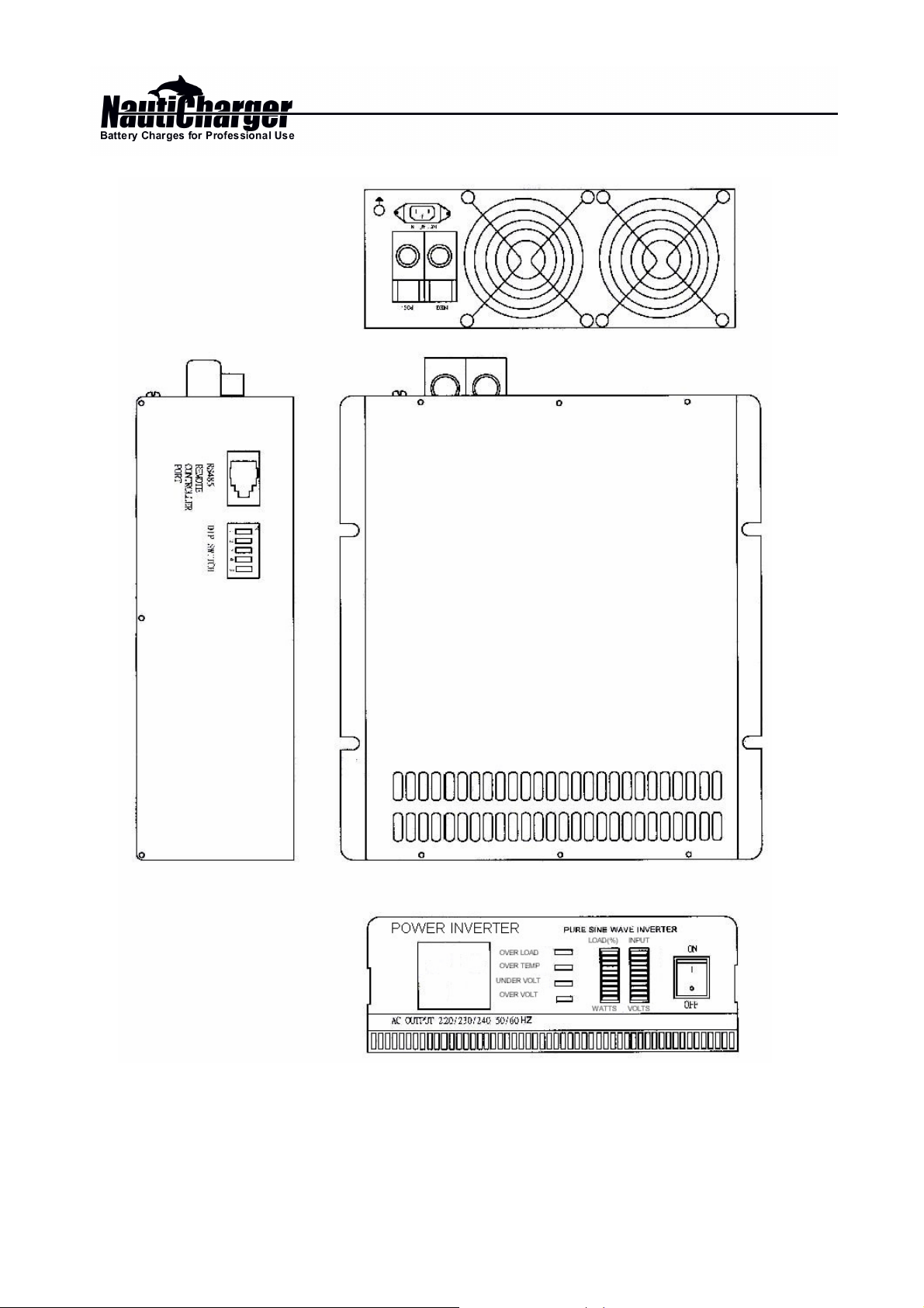
G-1. Unpack and inspect the power inverter, check to see that the
power switch in the OFF position.
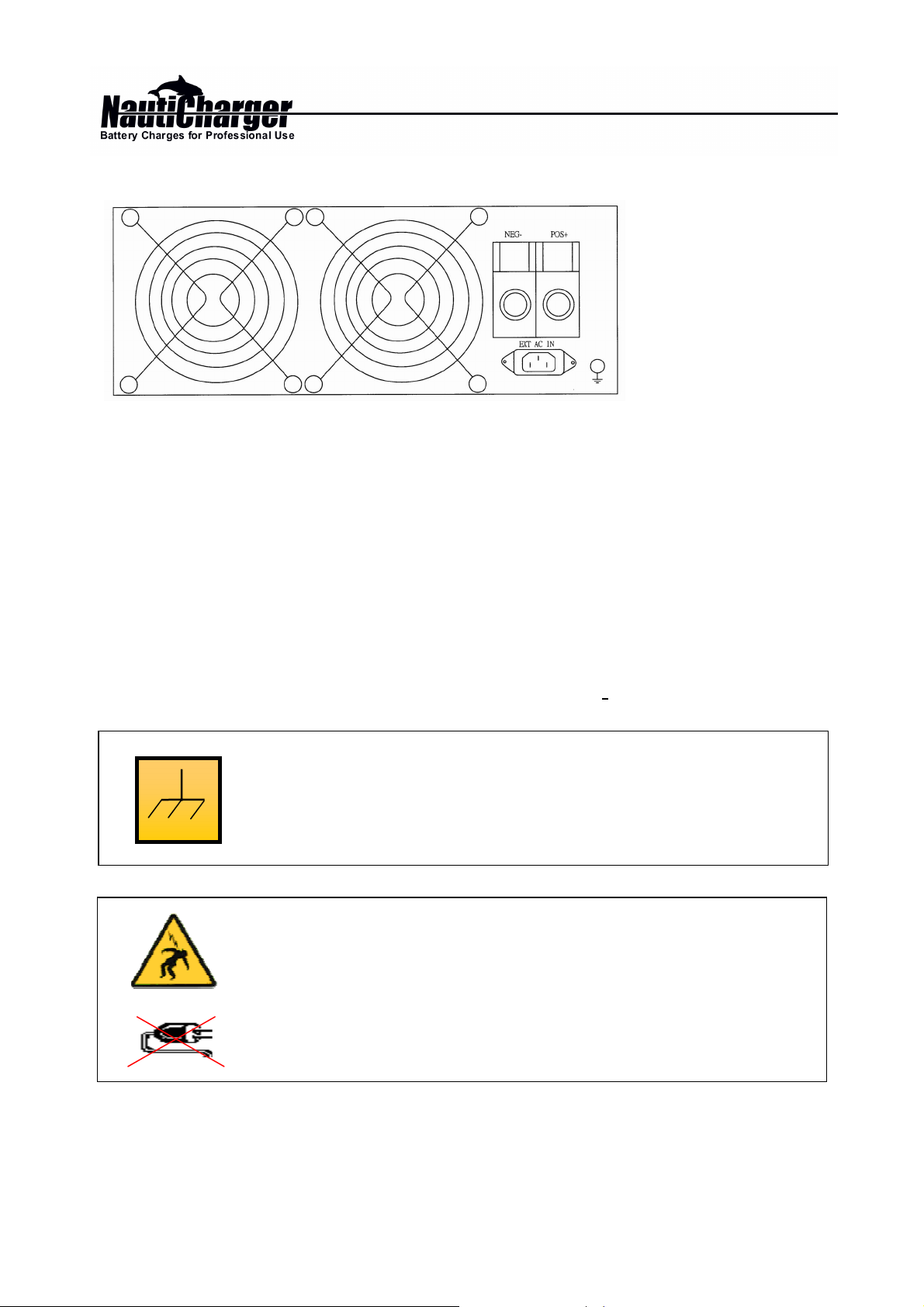
G-2. Connect the DC NEGATIVE cable to the Negative (NEG-)
terminal on the battery next, connect the cable to the negative
terminal on the inverter.
The connection to the negative terminal off the Inverter should
be the last connection made. A spark when making this final
connection is normal.
G-3. Before proceeding further, carefully check that cable you have
just connects from the negative terminal of inverter to the
gative output terminal of power source.
G-4. Connect the cable from the positive terminal of inverter to the
positive terminal of the power source. Make secure connection.
WARNING !
You may observe a spark when you make this connection since
current may flow to charge capacitors in the power inverter.
.
Do not make this connection in the presence of
flammable fumes, explosion or fire may result.
WARNING!
MakesurealltheDCconnectionsaretight(torqueto
9-10 ft-lbs,11.7-13Nm). Loose connections will
overheat and could result in a potential hazard.
CAUTION!
Reverse polarity connection will blow a fuse in Inverter and may
permanently damage the inverter.
Damage caused by reverse polarity connection is not
covered by our warranty.
¡
Ï
¡Ð

-8-
G-5. Set the power switch to the ON position. Check the meters
and indicators on the front panel of the inverter. The voltage
bar graph indicate depending on the voltage of the power
source. If does not, check your power source and the
connections to inverter. The other indicators should be off.
G-6. Set power inverter switch to the OFF position, the indicator
lights may blink and the internal alarm may sound
momentarily The is normal. Plug the test load into the AC
receptacle on the front panel of the inverter.
Leave the test load switch off.
G-7. Set power inverter switch to the ON position and turn the test
load on, the inverter should supply power to the load. If you
plan to measure the true output r.m.s. Voltage of inverter, the
meter such as FLUKE 45 BACKMAN
4410 or TRIPLETT 4200 must be used.
H. Installation:
H-1. Where to install
The power inverter should be installed in a location that meets
the following requirements:
H-1-1. Dry – Do not allow water to drip or splash on the inverter.
H-1-2. Col – Ambient air temperature should be between 0°C and
40°C,thecoolerthebetter.
H-1-3. Safe – Do not install in a battery compartment or other
areas where flammable fumes may exist, such
as fuel storage are as or engine compartments.
H-1-4. Ventilated – Allow at least one inch of clearance around the
inverter for air flow. Ensure the ventilation
openings on the rear and bottom of the unit are
notobstructed.

-9-
H-1-5. Dust-free –Do not install the Inverter in a dusty environment
where either dust, wood particles or other
filings/shavings are present. These can pulled
into the unit when the cooling fan is operating.
H-1-6. Close to battery/batteries –
Avoidexcessivecablelengthsbutdonotinstall
the Inverter in the same compartment as
batteries. Use the recommended wire lengths
and sizes (see section 7.3). Also do not mount
the Inverter where it will be exposed to the
gases produced by the battery. These gases are
very corrosive and prolonged exposure will
damage the Inverter.
H-2. AC safety Grounding
During the AC wiring installation, AC input and
output ground wires are connected to the
inverter. The AC input ground wire must connect
to the incoming ground from your AC utility
source.
The AC output ground wire should go to the
grounding point for
your loads ( for example, a distribution panel
ground bus ).
H-2-1. Neutral Grounding
H-2-1-1.
120V models: The neutral conductor of the AC output circuit of the
Inverter is automatically connected to the safety
ground during inverter operation. This conforms to
National Electrical Code requirements that
separately derived AC sources (such as inverter and
generators) have their neutral conductors tied to
ground in the same way that the neutral conductor

-10-
from the utility is tied to ground at the AC breaker
panel. For models configured with a transfer relay,
when AC utility power is present and the Inverter is
in bypass mode, this connection (neutral of the
Inverter’s AC output to input safety ground )is not
present so that the utility neutral is only connected to
ground at your breaker panel, as required.
H-2-1-2.
230V models: There is no connection made inside the Inverter from
either of the line conductors (line or neutral) to the
safety ground.
Ground Fault Circuit Interrupters (GFCI’S):
Installations in Recreational Vehicles (for North American
approvals) will require GFCI protection of all branch circuit
connected to the AC output of the hardwire terminal equipped
Inverter. In addition, electrical codes require GFCI protection of
certain receptacles in residential installations. While the true sine
wave output of the Inverter is equivalent to the waveform
provided by utilities, compliance with UL standards requires us to
test and recommend specific GFCI’s. State power has tested the
following GFCI-protected 15A receptacles and found that they
functioned properly when connected to the output of the Inverter.
H-3. Making DC Wiring Connections :
Follow this procedure to connect the battery cables to the DC
WARNING!
Do not operate the power inverter without
connectingittoground.
Electrical shock hazard may result.

-11-
input terminals on the Inverter. Your cables should be as short
as possible (ideally, less than 10 feet / 3 meters) and large
enough to handle the required current, in accordance with the
electrical codes or regulations applicable to your installation.
Cables that are not an adequate gauge (too narrow) or are too
long will Cause decreased inverter performance such as poor
surge capability and frequent low input voltage warnings and
shutdowns.
These low input voltage warning is due to DC voltage drop
across the cables from the inverter to the batteries. The linger
and narrower these cables, the greater the voltage drop.
I. Operation:
To operate the power inverter, turn it on using the ON/OFF switch
on the front panel. The power inverter is now ready to deliver AC
power to your loads. If you are operating several loads from the
power inverter, turn them on separately after the inverter has been
turned on. This will ensure that the power inverter does not have to
deliver the starting currents for all the loads at once.
I-1. Controls and indicators
The ON/OFF switch turns the control circuit in the power inverter
on and off.
It does not disconnect power from the power inverter.
The Inverter operates from an input voltage ranging from:
10 to 16 VDC for 12V models
20 to 32 VDC for 24V models
42 to 62 VDC for 48V models
Peak performance for these inverter occurs when DC input
voltage is in the Range of 10 volts to 16 volts for 12V models and
20 volts to 32 volts for 24V Models, and 42 volts to 62 volts for

-12-
48V models. From 600Watts up to 3000Watts.
I-2. Battery voltage indicator :
The battery voltage bar graph indicates the voltage at the input
terminals of the power inverter at low input current, this voltage is
very close to the battery voltage. At high input current, this voltage
will be lower than the battery voltage because of the voltage drop
across the cable and connections. Ideally, the voltage should
remain in the green Ares of the bar graph. If the voltage goes into
the red area at top and bottom of the graph, inverter may shut –
down.
I-3. Load watt indicator
The AC load watt bar graph indicates the power drawn from the
power inverter. It will indicate watt by loads. For long term
operation , the watt should in the green & orange area of the bar
graph. Short-term operation is possible with watt in the red area. If
the watt rises to the flash all bar, the inverter will protect itself.
I-4. Over voltage indicator :
The over voltage indicator indicates that the power inverter has
shut itself Down because its input voltage has been over detect
voltage 12 / 24V / 48VDC version.
I-5. Under voltage indicator :
The under voltage indicator indicates that the power inverter has
shut itself Down because its input voltage has been low than
detect voltage 12 / 24V / 48VDC.

-13-
I-6. Over temp indicator :
The over temp indicator indicates that the power inverter has shut
itself down because it has become overheated. The power
inverter may overheat because it has been operated at power
levels above its rating, or because it has been installed in a
location which does not allow it to dissipate heat properly. The
power inverter will restart automatically once it has cooled off.
I-7. Overload indicator :
The overload indicator indicates that the power inverter has shut
itself down Because its output circuit has been short circuited or
drastically overloaded.
Switch the ON/OFF switch to OFF, correct the fault condition, and
then switch the ON/OFF switch back to ON.
J. Operating limits:
J-1. Power output:
The inverter will operate most AC loads within its power rating.
When deeming whether a microwave over can be operated by
the inverter, remember that the power commonly advertised for
microwave ovens is the cooking power (the power delivered to
the food) not the power actually consumed by the microwave
oven. The microwave over will consume 40% to 100% more than
its advertised cooking power. Check the rating sticker on the
back of the over to determine its actual power draw.
The Power inverter may not be able to start some of this motor
even though their rated current draw is within the power inverter.
If motor refuse to start, observe the battery voltage indicator while
trying to Start the motor. If the battery voltage indicator drops
below 11 volts while inverter is attempting to start the motor, this
may be why the motor won’t start. Make sure that the battery
connections are good and that the battery is fully charged. If the

-14-
connections are good and the battery is charged, but the
voltage still drops below 11 volts, you may need to use a larger
battery.
K. Trouble shooting:
K-1. Common problems Television interference :
Operation of the power inverter can interfere with television
reception on Some channels. If this situation occurs, the
following steps may help to alleviate the problem.
Make sure that the chassis ground lug on the back of the
power inverter is solidly connected to the ground system of
your vehicle, boat or home.
Do not operate high power loads with the power inverter
while watching television.
Make sure that the antenna feeding your television provides
an adequate (“Snow free”) signal and that you are using
good quality cable between the antenna and the television.
Move the television as far away from the power inverter as
possible.
Keep the cables between the battery and the power inverter
as short as possible and twist them together with about 2 to
3 twists per foot.
This minimizes radiated interference from the cables.
K-2. Troubleshooting guide:
WARNING!
Do not open or disassemble Inverter, attempting to service
the unit yourself may result in a risk of electrical shock
or fire.

-15-
Problem and Symptoms
Possible Cause
Solution
Low output voltage Using average reading Use true RMS
110V : 95-105VAC,220V Voltmeter and cable.
220V : 190-210VAC See page 7
Point 6-7. of manual
Load LED bar flash. Overload Reduce load.
No output voltage.
Low input voltage.
Recharge battery,
And voltage indicator. check connections
In lower red zone and cable.
No output voltage.
Thermal shutdown
Improve ventilation
Over Temp indicator make sure ventilation
On, load less than: openings in inverter
1500W is not obstructed,
reduce ambient
temperature.
No output voltage, Short circuit or Wiring Check AC wiring
Over Load indicator Error. For short circuit or
On. Improper polarity (hot
and neutral reversed)
Very high power load Remove load

-16-
L. Maintenance
Very little maintenance is required to keep your inverter operating
properly.
You should clean the exterior of the unit periodically with a damp cloth
to regent accumulation of dust and dirt. At the same time, tighten the
screws on the DC input terminals.

-17-
Appendix A
A-1. Dip Switch (110V)
S1 S2 Function S3 S4 Output
voltage S5 Out
Frequency
OFF OFF DC/AC OUT MODE. OFF OFF 120V OFF 60Hz
OFF ON
DC/AC +GREEN POWER
MODE. ON OFF 115V ON 50Hz
ON OFF UPS MODE. OFF ON 110V
ON ON
UPS MODE +DELAY MODE
+GREEN POWER. ON ON 100V
Dip Switch (220V)
S1 S2 Function S3 S4 Output
voltage S5 Out
Frequency
OFF OFF DC/AC OUT MODE. OFF OFF 240V OFF 60Hz
OFF ON
DC/AC +GREEN POWER
MODE. ON OFF 230V ON 50Hz
ON OFF UPS MODE. OFF ON 220V
ON ON
UPS MODE +DELAY MODE
+GREEN POWER. ON ON 200V

-18-
A-2
NDC-AC Structure schema :
1. Code explanation:
(a) DC/AC OUT MODE :
No matter shore power has/ hasn’t the power the AC output is
supply by DC/AC (so the AC Transfer Switch is ON) ( No
Green Power Function).
(b) DC/AC OUT MODE + GREEN POWER MODE :
AC output power supply by DC/AC ( AC Transfer Switch ON )
When AC output load off DC/AC will turning to green power
mode to reduce the consummation of the Battery.
(c) UPS MODE :
When AC input has power the AC output power supply is by
AC input ( so the AC Transfer is in Switch OFF condition)
DC/AC Stand by.
When AC input cut off the power the AC Transfer Switch will be
in 10msec from OFF→ON at this time the AC output is supply
by DC/AC.
When AC input back to normal the AC Transfer Switch from
ON→OFF at this time the AC output power is again supply via
AC input.
About AC input power at stander voltage ±15%, above change will
AC INPUT
AC OUTPUT
NC
NO
COM
COM
AC Transfer Switch
NO
NC

-19-
also treat as power unusually so it will automatically Transfer to
DC/AC output this 15% Range can be setting from the Remote
controller
(d) UPS MODE + DELAY MODE + GREEN POWER :
UPS MODE + DELAY MODE :
Same as UPS mode the only different is when AC Transfer
Switch working it won’t complete in 10 m sec it will delay 5
second and than complete.
UPS MODE + DELAY MODE + GREEN POWER :
When AC input cut of the power the AC output is via DC/AC
output and when the AC output load off the DC/AC will turning
into green power mode to reduce the consummation of the
Battery.
High Frequency
Model No.
PM-600H-12xx
PM-600H-24xx
PM-1000H-12xx
PM-1000H-24xx
PM-1500H-12xx
PM-1500H-24xx
PM-2000H-12xx
PM-2000H-24xx
PM-3000H-12xx
PM-3000H-24xx
Continuous Output power 600W 1000W 1500W 2000W 3000W
Output power surge 800W 1400W 2000W 2800W 4200W
AC Output voltage 100/110/120V ± 2% 220/230/240V ± 2% DIP switch select
Output voltage Regulation -8% / ± 3% All models
Output frequency 50 / 60 Hz selectable ±0.05% Accuracy
Output Wave form Pure Sine Wave < 3% THD
Efficiency (Full Load) 83%~85%
No Load power consumption <1.5W (In power saving mode.)
Input voltage range 10V – 16VDC,20V-32VDC
Power saving recovery time 1 second
AC Transfer time (UPS-mode) < 10msec max
LED status indicators High/Low battery shutdown, over temperature shutdown, overload shutdown /
input DC voltage scale meter & output watts percent scale metter.
Protection Feature
* Remote controller option.
Over load, short circuit, over/under input voltage, over temperature, reverse
input polarity (by fuse).
RS485 Remote controller Power output ON/OFF, green power mode, reset, error message, …etc.
Operation temperature range 0~50(32°~122°F)
Storage temperature range -30~70(-22°~158°F)
Dimensions L x W x Hmm 370x270x120 420x270x120 470x270x120 470x270x190 530x270x190
Weight 9.92 (Lbs.)
4.5 (Kgs)
12.13 (Lbs.)
5.5 (Kgs)
15.43 (Lbs.)
7 (Kgs)
22.05 (Lbs.)
10 (Kgs)
26.46 (Lbs.)
12 (Kgs)
Remote controller is optional
This manual suits for next models
4
Table of contents
Other NautiCharger Inverter manuals
Popular Inverter manuals by other brands

Amane Studio
Amane Studio IP8E manual

ZUCCHETTI
ZUCCHETTI AZZURRO 3PH 3.3KTL-12KTL-V3 user manual

C.E. Nierhoff & Co
C.E. Nierhoff & Co C528 troubleshooting guide

Victron energy
Victron energy Quattro 12/5000/220-100|100-230V manual

Cobra
Cobra CPI 200 CH operating instructions

Growatt
Growatt WIT 50-100K-A-US quick guide