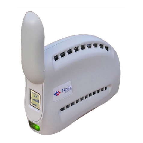
Navini Networks Ripwave-MX 2400-2483 LMX E User manual

R
Ri
ip
pw
wa
av
ve
e™
™-
-M
MX
X
M
Mo
od
de
em
m
U
Us
se
er
r
G
Gu
ui
id
de
e
For use with all Ripwave-MX Modem models
Part Number 40-00097-00
Revision J, Version 1.0, PV1.5
August 1, 2005
Proprietary
All information disclosed by this document is the proprietary property of Navini Networks, Inc. and is protected
by copyright, trademark, and/or trade secret laws. All rights therein are expressly reserved.

Navini Networks, Inc. Ripwave-MX Modem User Guide
TABLE OF CONTENTS
PERMISSIONS, TRADEMARKS & DISTRIBUTION.............................................................................3
SAFETY .......................................................................................................................................................4
REGULATORY INFORMATION..............................................................................................................5
BATTERY PRECAUTIONS........................................................................................................................6
INTRODUCTION.......................................................................................................................................7
PACKAGE INVENTORY.........................................................................................................................7
RIPWAVE-MX MODELS.........................................................................................................................7
OPERATING FREQUENCIES .........................................................................................................................8
MINIMUM COMPUTING REQUIREMENTS......................................................................................8
PHYSICAL CHARACTERISTICS..........................................................................................................9
INSTALLING THE LMX MODEM ......................................................................................................10
ACCESSING THE INTERNET..............................................................................................................12
TROUBLESHOOTING...........................................................................................................................12
LCD DISPLAY..........................................................................................................................................12
INSTALLING NAVINI DIAGNOSTICS (NAVDIAG)........................................................................14
TROUBLESHOOTING USING NAVINI DIAGNOSTICS (NAVDIAG)..........................................17
UNINSTALLING NAVINI DIAGNOSTICS (NAVDIAG)..................................................................23
OPTIONAL BATTERIES .......................................................................................................................24
OPTIONAL EXTERNAL BATTERY PACKS...................................................................................................24
CONNECTING THE STANDARD EXTERNAL BATTERY PACK (S-EBP)........................................................25
THE INDICATOR LIGHT ON THE STANDARD EXTERNAL BATTERY PACK (S-EBP)....................................26
CHARGING THE STANDARD EXTERNAL BATTERY PACK (S-EBP)............................................................26
CONNECTING AND DISCONNECTING THE HEAVY DUTY EXTERNAL BATTERY PACK (HD-EBP).............27
THE INDICATOR LIGHT ON THE HEAVY DUTY EXTERNAL BATTERY PACK (HD-EBP) ............................28
CHARGING THE HEAVY DUTY EXTERNAL BATTERY PACK (HD-EBP) ....................................................29
CARE & MAINTENANCE.....................................................................................................................29
UPGRADING THE MODEM.................................................................................................................30
ADDENDUM 1: RIPWAVE™-MX MODEM - PC TROUBLESHOOTING....................................32
ADDENDUM 2: END USER SOFTWARE LICENSE AGREEMENT.............................................37
2
050801_pv1.5_Ripwave-MX Modem User Guide_40-00097-00j(4.3.1)

Navini Networks, Inc. Ripwave-MX Modem User Guide
Permissions, Trademarks & Distribution
Na
Un
co
Copyright©2001 - 2005, Navini Networks, Inc. All information contained herein and disclosed by this
document is confidential and the proprietary property of Navini Networks, Inc. and all rights therein are
expressly reserved. Acceptance of this material signifies agreement by the recipient that the information
contained in this document is confidential and that it will be used solely for the purposes set forth herein.
Acceptance of this material signifies agreement by the recipient that it will not be used, reproduced in
whole or in part, disclosed, distributed, or conveyed to others in any manner or by any means – graphic,
electronic, or mechanical, including photocopying, recording, taping, or information storage and retrieval
systems – without the express written permission of Navini Networks, Inc.
vini Networks is a registered trademark. The Navini Networks logo, Zero-Install, Ripwave, and
wired by Navini are trademarks of Navini Networks, Inc. Other product and company names
mentioned herein may be trademarks and/or service marks of their respective owners.
Except for the hardware warranty, nothing herein constitutes any representation, warranty,
assurance, or guaranty of any kind.
Because of continuing developments and improvements in design, manufacturing, and deployment,
material in this document is subject to change without notification and does not represent any
mmitment or obligation on the part of Navini Networks, Inc.
Navini Networks, Inc. shall have no liability for any error or damages resulting from the use of this
document.
All Navini Networks logos and trademarks are the property of Navini Networks, Inc. Unauthorized usage
is strictly prohibited without the express written permission of Navini Networks, Inc.
©2001 - 2005 Navini Networks, Inc. All rights reserved.
3
050801_pv1.5_Ripwave-MX Modem User Guide_40-00097-00j(4.3.1)

Navini Networks, Inc. Ripwave-MX Modem User Guide
Safety
When using Navini Ripwave electronic equipment, always follow basic safety precautions to reduce the
risk of electrical shock, fire, and injury to people and/or property. Follow all warnings and instructions
that come with the equipment.
1. Do not use the equipment while you are in a bathtub, shower, pool, or spa. Exposure of the
equipment to water could cause severe electrical shock or serious damage to the equipment.
2. Do not immerse the equipment in any type of liquid. Use a damp clothe and if needed, water and a
mild detergent to clean the plastic shell. Unplug the equipment from the
power source before
cleaning.
0
source may cause
damage to the equipment.
e with
r manual.
. Do not use a frayed or damaged power cord. Do not place the power cord where it can be stepped on
. Do not overload wall outlets, power strips, or extension cords. This can cause serious electrical shock
lace the equipment on an unstable surface. It can fall and cause injury or damage to the
equipment.
trical shock. Only
an authorized repair technician should service this product.
1. Do not expose the equipment to extreme hot or cold temperatures.
2. Do not use the equipment under the following conditions:
• When the equipment has been exposed to water or moisture.
• When the equipment has been damaged.
• When the power cord is damaged or frayed.
• ance.
3. Follow all airport and FAA regulations when using the equipment on or near aircraft.
4. Only operate the equipment from the type of power source(s) indicated in this manual (110/22
VAC, 60/50 Hz adapter or Navini supplied battery). Any other type of input power
5. Power the equipment using only the battery or the AC adapter cable provided, and in accordanc
the instructions specified in the use
6
or tripped over.
7. Do not touch wires where the insulation is frayed or worn unless the equipment has been
disconnected from its power source.
8
or fire.
9. Do not p
10. Do not disassemble the equipment. Removing covers exposes dangerous voltages or other risks and
also voids the warranty. Incorrect reassembly can cause equipment damage or elec
1
1
When the equipment does not operate properly or shows a distinct change in perform
4
050801_pv1.5_Ripwave-MX Modem User Guide_40-00097-00j(4.3.1)

Navini Networks, Inc. Ripwave-MX Modem User Guide
Regulatory Information
is a Radio Frequency transmitter. It is required to comply with FCC RF
mount
aintained,
ditions:
ff and on, the user is encouraged
ing measures:
e equipment and the receiver,
a circuit that is different from the one to which the
4) Consult the dealer or an experienced radio/TV technician for additional suggestions.
INFORMATION TO USER
This device has been authorized as a radio frequency transmitter under the appropriate rules of the
Federal Communications Commission. Any changes or modifications not expressly approved by
Navini Networks could void the user’s authority to operate the equipment.
FCC Notice
CAUTION: This device
exposure requirements for transmitting devices. For all LMX Modems except for the 2.6 LMX
with window mount, a minimum separation distance of 8 inches (20 cm) or more must be
maintained between the antenna and all persons during device operations to ensure compliance
with the FCC’s rules for Radio Frequency Exposure. For the 2.6 LMX Modem with a window
mount, a minimum of 8.3 inches (21 cm) or more must be maintained between the window
antenna and all persons during device operations. If this minimum distance cannot be m
exposure to RF levels that exceed the FCC’s limits may result.
FCC Compliance and Advisory Statement
Tested To Comply
With FCC Sta
ndards
This equipment has been tested and found to comply with the limits for a class B digital device,
Pursuant to Part 15 of the FCC rules. The operation is subject to the following two con
(1) This device may not cause
FOR HOME OR OFFICE US
E
harmful interference, and
(2) This device must accept any interference received, including interference that may cause
undesired operation.
These limits are designed to provide reasonable protection against harmful interference in a
residential installation. This equipment generates, uses, and can radiate radio frequency energy
and, if not installed or used in accordance with the instructions, may cause harmful interference to
radio communications. However, there is no guarantee that interference will not occur in a
particular installation. If this equipment does cause harmful interference to radio or television
reception, which can be determined by turning the equipment o
to try to correct the interference by one or more of the follow
1) Reorient or relocate the receiving antenna,
2) Increase the separation between th
3) Connect the equipment to an outlet on
receiver is connected,
5
050801_pv1.5_Ripwave-MX Modem User Guide_40-00097-00j(4.3.1)
Navini Networks, Inc. Ripwave-MX Modem User Guide
Battery Precautions
CAUTION! To reduce risk of injury or fire, follow these instructions when handling the battery.
1. Ris
2. Do
disp
3. Do
har
imm
4. Do ns except per the instructions in this manual.
5. If u l om the equipment if the equipment is not
goi to be used for a ak and cause damage to the
equipment.
6. Exe
suc bra
7. Store the battery pack in a dry place, 0 to +40 degrees Celsius.
8. Dis
k of explosion is possible if the battery is replaced with one not supplied by Navini Networks.
not dispose of the battery in a fire. They may explode. Check with the local codes for battery
osal guidelines.
not open or mutilate the battery. The battery contains substances that are toxic, corrosive, or
mful to humans. If battery substances come in contact with the skin, seek medical help
ediately.
not attempt to recharge the battery by any mea
sing an optional interna battery, remove the battery fr
ng long period of time. The battery could le
rcise care when handling the battery to prevent shorting the battery with conducting materials
h as celets, rings, and keys.
pose of used batteries according to environmental guidelines.
6
050801_pv1.5_Ripwave-MX Modem User Guide_40-00097-00j(4.3.1)
Navini Networks, Inc. Ripwave-MX Modem User Guide
Introduction Con
(LM
nomadic service availability as a computer with this device is
as long as there is coverage in the area.
Package
ventory Please verify the contents of your LMX Modem package. If you do
not find all of these items in your package, notify the supplier fro
In
M
gratulations! The Liquid Cystal Display Ripwave™-MX
X) dual-mode Modem is a user-friendly, easy-to-install device
that helps you connect wirelessly to the Internet. It provides
complete broadband Internet access to residential and small
professional hardware installation. The LMX Modem also provides
moved from room to room, location to location, or even city to city
m
whom you obtained it.
• LMX Modem
• PC-to-LMX Modem cable (Ethernet straight cable)
• Navini Diagnostics Installation CD
X Modem will operate in either the 2.4 GHz, 2.5-2.7
ed on the next page.
• LMX Modem AC power adapter
• Ripwave-MX Modem User Guide (on CD)
• Ripwave-MX Modem Quick Installation Guide
X Models
Your LM
L
GHz, 3.4 GHz, or 3.5 GHz range. Within each frequency range
there are several model types, describ
office/home office (SOHO) customers without the necessity of
2.4, 2.5-2.7, 3.4 & 3.5
GHz LMX Modem
7
050801_pv1.5_Ripwave-MX Modem User Guide_40-00097-00j(4.3.1)
Navini Networks, Inc. Ripwave-MX Modem User Guide
Operating
Frequencies
equirements
ee, also, Addendum 1)
Minimum
omputingC
R
(S
Modem Model Frequency Range Operating
Band
2.4 GHz
LMX
2400-2483
LMX E 2.400 GHz – 2.483 GHz ISM
2.5 – 2.7
GHz LMX
2.5-2.6 LMX
E 2.500 GHz – 2.686 GHz MMDS/ITFS
3.4 GHz
LMX
3410-3525
LMX E 3.410 GHz – 3.525 GHz BWA/FWA
3.5 GHz
LMX
3475-3600
LMX E 3.475 GHz – 3.600 GHz BWA/FWA
The “E” in the model name stands for Ethernet. Your computer
indows®95 or later).
should have this port for connecting the Modem.
• An Ethernet connection will function with any Win32®
em (WOperating Syst
Operating
System1: Ethernet Modems: Any Win32 Operating System
(OS) - Windows 952, Windows NT, Windows 983,
E3,
Ensure that the pc network port is enabled.
Windows 98SE3, Windows 2000, Windows M
Windows XP4, or later version.
General Information:
CPU: Pentium level or higher
RAM: 32 MB or the Operating System minimum,
whichever is greater
Hard Drive: 50 MB free disk space for either monitoring
software (Navini Diagnostics Tool) 5
Monitor: 256 colors, 800 x 600 resolution
1NOTE: To upgrade your Operating System after loading the Navini
Diagnostics software, you must first uninstall Navini Diagnostics prior to
upgrading the OS. Otherwise, Navini Diagnostics will not work. See Uninstall
structions in this Guide.
Internet Explorer 3.0 or higher is required for installation on Windows
5 Operating Systems.
The LMX Modem must be left powered ON whenever you shut down
r restart any Windows 98 or ME platforms. If the Modem is off, a blue screen
pears on the monitor. In the event that happens you will most likely have to
ower cycle the PC.
Windows XP must be Service Pack Level 1 or higher.
Navini Diagnostics software is supported on Win98, Win98SE,
in2000, WinME, WinXP or higher, Mac X (also called Mac10) or higher, or
in
2NOTE:
9
3NOTE:
o
ap
p
4NOTE:
5NOTE:
W
8
050801_pv1.5_Ripwave-MX Modem User Guide_40-00097-00j(4.3.1)
Navini Networks, Inc. Ripwave-MX Modem User Guide
hysical
haracteristics
ed Hat Linux 8.0 or higher. Mac users must have the Snuffit extraction
sof
T ual yo roc f installing
t X Mo softw dev d to
o e v alu
T z sed in most of the illustrations in this
m her no 2.5 3.5
G els
you experience any difficulties with your unit, please contact
ur
e
Rip
odems (2.4, 2.5-2.7, 3.4, & 3.5 GHz)
P
C
R
tware.
his man
he LM
will guide
dem and
u through the simple p
are, which has been
ess o
elope
ptimize th
H
ease and con enience for you, our v ed customer.
he 2.6 G
anual w
model is u
e there are differences in the 2.4, -2.7, 3.4 &
Hz mod .
If
your Service Provider or the vendor from whom you obtained yo
LMX Modem.
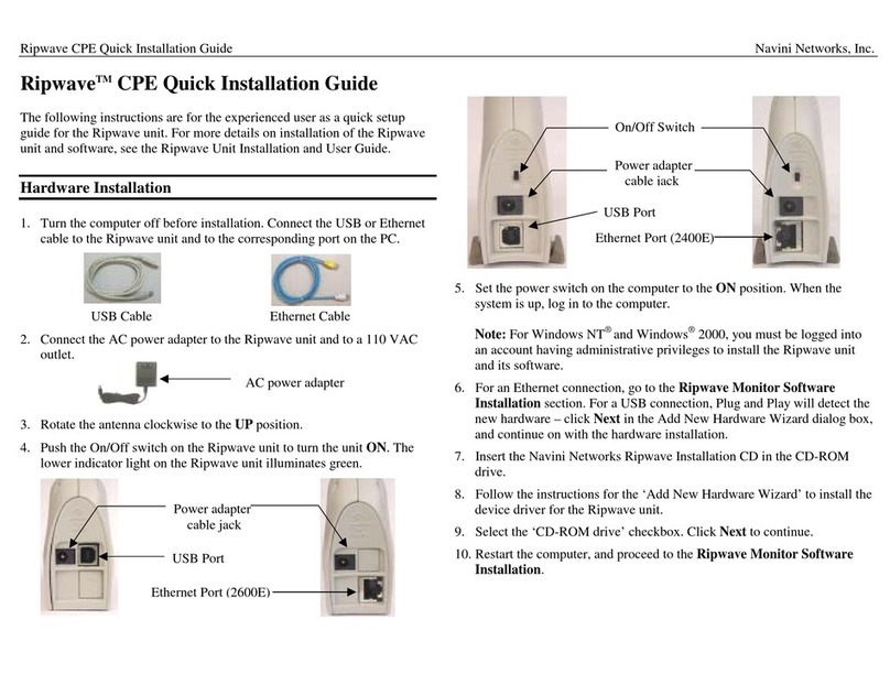
Th following figure shows the physical characteristics of the
wave-MX LMX Modems.
LMX M
Front
Antenna
Liquid Crystal Display
On/Off Button
Back
Power Adapter Connection
Ethernet Cable Connection
Front
Antenna
Liquid Crystal Display
On/Off Button
Front
Antenna
Liquid Crystal Display
On/Off Button
Back
Power Adapter Connection
Ethernet Cable Connection
Back
Power Adapter Connection
Ethernet Cable Connection
9
050801_pv1.5_Ripwave-MX Modem User Guide_40-00097-00j(4.3.1)
Navini Networks, Inc. Ripwave-MX Modem User Guide
Installing the
MX Modem
ee, also, Addendum 1)
wing instructions are for the installation of the LMX
L
(S
The follo
Modem. Please read all instructions before attempting the
installation. It is advisable to turn off the computer and the LMX
Modem before performing the installation.
Step Action Illustration
1. Connect the Ethernet
cable to the Ethernet
port on the computer.
2. Connect the other end of
the Ethernet cable to the
LMX Modem.
3. Connect the AC power
adapter to the LMX
Modem. Plug the other
end into a 110/220 VAC
60/50 Hz outlet.
CAUTION! Only use
the AC power adapter
specifically supplied
with the LMX Modem.
Using any other adapter
may cause damage to
the Modem.
Connection for
Ethernet cable
Connection for
Ethernet cable
Connection for
Power Adapter
Connection for
Power Adapter
10
050801_pv1.5_Ripwave-MX Modem User Guide_40-00097-00j(4.3.1)

Navini Networks, Inc. Ripwave-MX Modem User Guide
Installing the LMX
Modem, continued
Step Action Illustration
4. Rotate the antenna on
the LMX Modem
clockwise 180 degrees
to the UP position. This
reveals the LMX
or
movement of the
antenna in any other
direction may cause
damage to the LMX
Modem.
Modem liquid crystal
display (LCD).
CAUTION! Rotation
5. Turn the Modem ON by
pushing the On/Off
button in.
6. If the LCD turns on,
proceed to Step 7. If not
there is a problem with
the Modem or the AC
power adapter. Ch
,
eck all
cables for proper
connection. If there is
still a problem, contact
the supplier who gave
you the package.
Antenna
Liquid Crystal
Display
Antenna
Liquid Crystal
Display
Liquid Crystal
Display
On/Off ButtonOn/Off ButtonOn/Off Button
Liquid Crystal
Display (LCD)
Liquid Crystal
Display (LCD)
11
050801_pv1.5_Ripwave-MX Modem User Guide_40-00097-00j(4.3.1)

Navini Networks, Inc. Ripwave-MX Modem User Guide
Installing the LMX
Modem, continued
Accessing the
nternet
roubleshooting
CD Display
I
T
L
Step Action Illustration
7.
Turn your computer on
and log in.
8. Proceed to the
“Troubleshooting”
section of this manual.
With your Modem
com
access the Internet, open the web browser that is installed on your
compu
After installation, if you are experiencing difficulties with your
rne w th
Requir m 1 to ensure your computer meets
those r s. Next, go back over the installation procedures
and ensure those steps were completed properly.
Assuming the computer requirements are met and the installation
steps were completed as required, you will need to observe the
signal sync and signal strength indicators on the LMX Modem.
You also may need to install the monitoring software. This
software, called the Navini Diagnostics, is provided on a CD that
came in your Modem package. The Navini Diagnostics software
assists in solving connection problems as well as providing other
uab
The LCD Display is a text-based display that provides valuable
inform em’
conjun software, you can troubleshoot
signal issues, network connections, and power problems.
now installed, and both the Modem and
puter power on, you should be able to surf the Internet! To
ter.
Inte t connection, please revie
ements and Addendu
equirement
e Minimum Computing
val
le information.
ation about the LMX Mod
ction with the monitoring
s operation. Used in
CONNECTED
Q
S
CONNECTED
Q
SS
12
050801_pv1.5_Ripwave-MX Modem User Guide_40-00097-00j(4.3.1)

Navini Networks, Inc. Ripwave-MX Modem User Guide
LCD Display, continued fo finitions for the LCD in ications.
The llowing table provides de d
LCD Indicator:
SEARCHING
Blinking flash: Syncing
CONNECTED: Locked-on
S: Signal Strength Meter (SSI)
0 bars S<100
1 bar -99<S≤-100
2 bars -96<S≤-99
3 bars -92<S≤-95
4 bars -88<S≤-91
5 bars -84<S≤-87
6 bars -80<S≤-83
7 bars -76<S≤-79
8 bars -70<S≤-75
Q: Signal Quality Meter (SNR)
0 bars Q<10
1 bar 10<Q≤-12
2 bars 13<Q≤-14
3 bars 15<Q≤-16
4 bars 17<Q≤-18
5 bars 19<Q≤-20
6 bars 21<Q≤-22
7 bars 23<Q≤-24
8 bars Q≥24
Activity Indicator:
Flashing arrows: Traffic (both arrows flash)
Blank: No Traffic Activity
13
050801_pv1.5_Ripwave-MX Modem User Guide_40-00097-00j(4.3.1)

Navini Networks, Inc. Ripwave-MX Modem User Guide
Installing Navin
iagnostics i
NavDiag)
ote: The screenshots shown in these instructions were taken from
E operating system, the screens you see may vary from the
the instructions.
D
(
N
a laptop with Windows 2000. If you have a Windows 98, XP, or
M
screens shown in
Step Action Illustration
1. Shut down all pro
including anti-viru
grams,
before installing the
Navini Di
software.
s
software programs,
agnostics
2. Insert the
Diagnositcs Installation
CD into the CD-ROM
drive.
Navini
3. Open the CD by clicking
the folder
Navini_Diagnostics.
on the My Computer
icon. Double-click on
named
4. Double-click on the icon
for the file
navdiag_ xe*.
This will lly
start the installation of
Navini Diagnostics.
s running Mac
ac.sit or
ile. Mac
users will need the Snuffit
extraction software.
Example:
windows.e
automatica
*If your PC i
or Linux software, you will
need the navdiag_m
navdiag_linux.bin f
5. The InstallAnywhere
window appears. The
progress bar indicates
that InstallAnywhere has
initialized.
Windows 2000 Screen
14
050801_pv1.5_Ripwave-MX Modem User Guide_40-00097-00j(4.3.1)

Navini Networks, Inc. Ripwave-MX Modem User Guide
050801_pv1.5_Ripwave-MX Modem User Guide_40-00097-00j(4.3.1)
ag),
Installing Navini
Diagnostics (NavDi
continued
Step Action Illustration
6. The Navini Diagnostics
Language screen
appears*. Select a
and click OK
Windows 2000 Screen
language
to continue.
7. The progress bar
indicates the files being
installed.
Windows 2000 Screen
8. The Navini Diagnostics
Introduction screen
appears. Click Next to
continue.
Windows 2000 Screen
9. t
ead the
e License
Agreement is not
accepted, you cannot
install the software.
Windows 2000 Screen
The License Agreemen
creen appears. Rs
Licensing Agreement.
Select the I Accept
option, and click Next to
continue.
NOTE: If th
15

Navini Networks, Inc. Ripwave-MX Modem User Guide
Installing Navini
iag),Diagnostics (NavD
continued
Step Action Illustration
10. The Choose Install
the
ish to
continue.
NOTE: The default
installation folder provided
by the software is shown in
the illustration.
Folder screen appears.
Enter the name of
folder where you w
install the software.
Click Next to
Windows 2000 Screen
11. cut
am Group,
and click Next to
continue.
Windows 2000 Screen
The Choose Short
Folder screen appears.
Select the default, In a
new Progr
12.
eview the
ontents for accuracy.
lick Install to
ontinue.
or your installation and
omputer, this screen
ay have different
The Pre-Installation
Summary screen
appears. R
c
C
c
F
c
m
information than what is
shown in the illustration.
Windows 2000 Screen
13. The Installing screen
will display as the
application files are
loaded.
16
050801_pv1.5_Ripwave-MX Modem User Guide_40-00097-00j(4.3.1)

Navini Networks, Inc. Ripwave-MX Modem User Guide
Installing Navini
iagnostics (NavDiag),
ontinued
roubleshooting
sing Navini
iagnostics
NavDiag)
D
c
T
U
D
(
Step Action Illustration
14. At the Install Complete
screen, click Done to
window.
Windows 2000 Screen
close the
pe s s
on the Navini Diagnostics icon on your desktop.
To o n the Navini Diagnostic oftware application, double-click
Navini Diagnostics.lnk
The Connection Status screen will open and display data if the
Modem is in session. The screen will refresh live data every
second.
17
050801_pv1.5_Ripwave-MX Modem User Guide_40-00097-00j(4.3.1)

Navini Networks, Inc. Ripwave-MX Modem User Guide
Troubleshooting Using
continued
sent the PC, the co een the PC and the
em ction betwee
Base Station, and the Base Station to which the Modem
commu rks over the connections indicate
working connections.
If the connection between the PC and the Modem or between the
odem and the Base Station is interrupted, an “X” is positioned
ver the corresponding icon.
The Signal Strength and Signal Quality are dynamic bar areas that
dicate how well your Modem is receiving signals from the Base
ceived by the Modem. The strength of the signal is
represented by a group of colored bars. The higher the pile of bars
Navini Diagnostics
(NavDiag),
The icons repre nnection betw
Mod , the Modem, the conne
nicating. Check ma
n the Modem and the
is
M
o
in
Station. In particular, the Signal Strength bar area graphically
represents the strength of the Absolute BTS Synchronization
Signal re
goes, the stronger the signal is. The color of the bars also gives an
indication of the strength of the signal. Green lines indicate an
excellent signal. Orange lines indicate a good signal while red lines
indicate a weak signal.
18
050801_pv1.5_Ripwave-MX Modem User Guide_40-00097-00j(4.3.1)

Navini Networks, Inc. Ripwave-MX Modem User Guide
Troubleshooting Using
Navini Diganostics
(NavDiag), continued
The Signal Quality bar area graphically represents the Signal-to-
Noise Ratio (SNR) of the downlink access code channel (ACC)
received by the Modem. Again, the quality of the signal is
represented by a group of colored bars. The higher the pile of
goes, the better the SN
bars
R of the signal. The color of the bars also
ives an indication of the quality of the signal. Green lines indicate
n a good signal while red
nes indicate a weak signal.
o increase the strength and quality of the signal, change the
cation of the LMX Modem. Try moving it closer to a window, to
le
is repositioned, observe the Signal
trength and Signal Quality bars. Position the Modem for
he History graphs plot the change in signal strength and signal
uality over time. The graphs cover the last minute and are updated
very second. Read the graphs from right to left. The right side of
t of the Connection Status screen, are four parameters.
hese parameters are BTS ID, Network ID, Active SW Version,
nd Standby SW Version. The BTS ID and Network ID indicate
e BTS to which the Modem is currently synchronized and the
etwork in which the Modem is operating. Active SW Version and
tandby SW Version indicate the version number of the software
urrently loaded in the “active side” and “standby side” of the
odem’s flash memory.
g
a excellent signal. Orange lines indicate
li
T
lo
a higher location, away from other wireless devices (microwave
ovens, cordless phones), and away from metal objects (shelves, fi
cabinets). As the LMX Modem
S
maximum signal strength and quality.
T
q
e
the graph represents the most recent status of your Modem.
A the bottom
T
a
th
n
S
c
M
19
050801_pv1.5_Ripwave-MX Modem User Guide_40-00097-00j(4.3.1)

Navini Networks, Inc. Ripwave-MX Modem User Guide
Troubleshooting Using
Navini Diganostics
(NavDiag), continued
The two letters in parenthesis following the release number
indicate the type of software load. JD indicates Joint Detection,
while EN indicates Enhanced Nulling.
On the left-hand side of the screen, there are five screen option
Connection Status, Configuration, Trend Analysis, Statistics, and
About. The following screen will appear when you press the
Configuration button.
s:
h date your Modem’s
ftware if you are so directed by your Service Provider. If you
ust update your Modem’s software, your Service Provider will
rovide you with instructions regarding what to do.
he Allow Customer Satisfaction Reporting box gives you control
ver whether your Service Provider is allowed to monitor your
odem using the remote CPE Logging function and to use your
ess
T e Configuration screen enables you to up
so
m
p
T
o
M
computer to store the CPE log files created by this function. By
default, this box is checked which means the Service Provider can
monitor your Modem.
The Trend Analysis screen enables you to view how some Modem
parameters evolve over time. With this screen, you can select up to
three parameters to plot. To view the Trend Analysis screen, pr
the Trend Analysis button.
20
050801_pv1.5_Ripwave-MX Modem User Guide_40-00097-00j(4.3.1)
This manual suits for next models
3
Table of contents
Other Navini Networks Modem manuals

Navini Networks
Navini Networks Ripwave Surfer 1239 User manual

Navini Networks
Navini Networks Ripwave MX User manual

Navini Networks
Navini Networks Ripwave 2300E/U User manual

Navini Networks
Navini Networks Ripwave 40-00097-00 User manual

Navini Networks
Navini Networks Ripwave CPE User manual

Navini Networks
Navini Networks Ripwave User manual