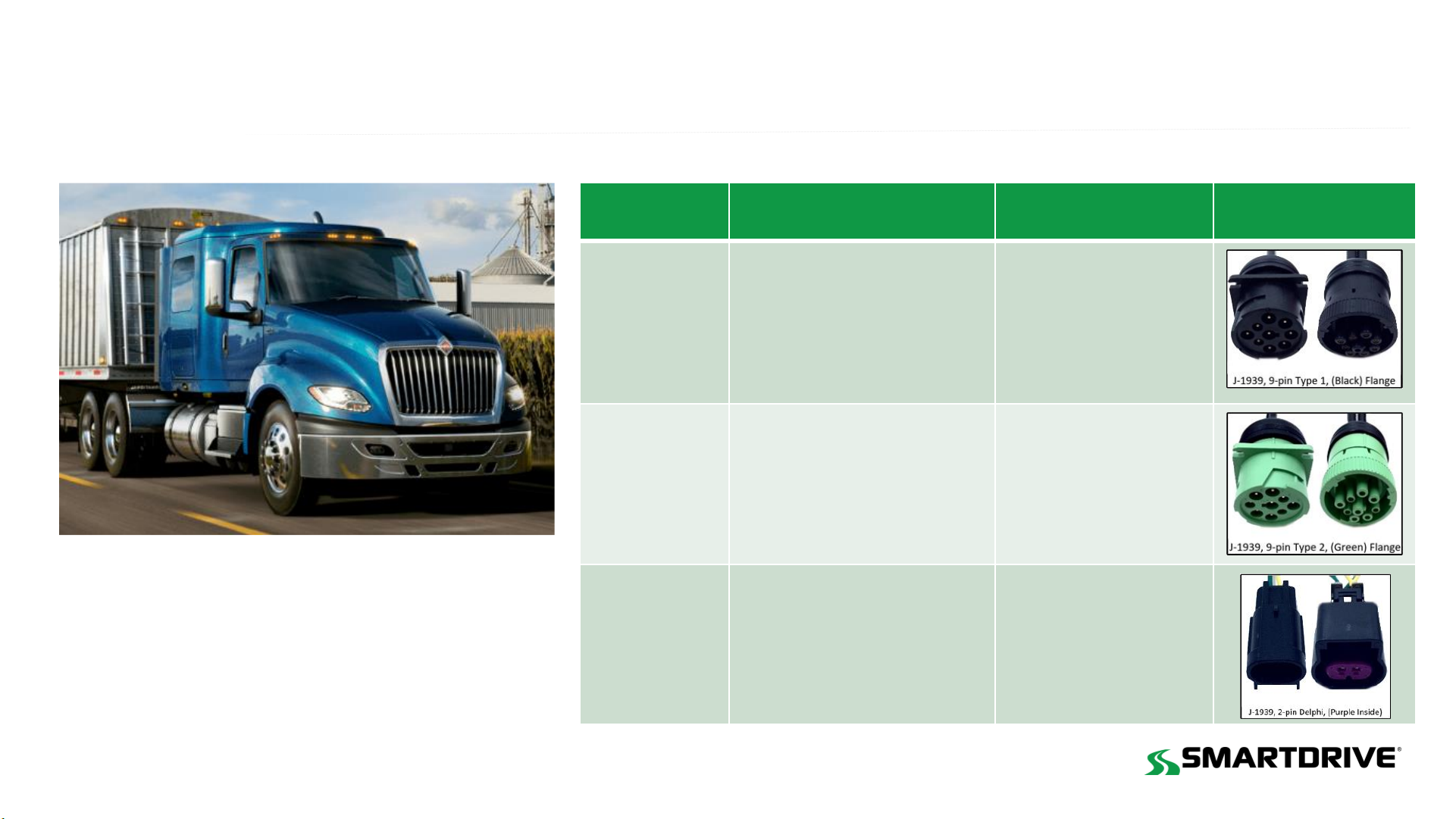
Navistar SmartDrive SR4 International LT 625 Series User manual

International LT625
COMPANY CONFIDENTI AL
© 2019 SmartDrive Systems, Inc. This information is intended for use by SmartDrive customers only. Any other use without the express written consent of SmartDrive Systems, Inc. is strictly prohibited. Rev 5, August 04, 2020
SmartDriveTM SR4 International LT Series 625 Installation Guide
Manufactured by Navistar Inc.
Released between 2016-Present
This VSA covers models manufactured between 2016-2021

International LT625
COMPANY CO NFIDENTI AL
© 2019 SmartDrive Systems, Inc. This information is intended for use by SmartDrive customers only. Any other use without the express written consent of SmartDrive Systems, Inc. is strictly prohibited. Rev 5, August 04, 2020
Year Range SR4 Harness Description SR4 SKU Cable Type
Released
2016
J1939 & J1708
9 Pin Type 1
Black flange
104
-0009-0018-00
2017-2020 J1939, 9 Pin Type 2,
Green Flange
104
-0009-0005-00
2021 J-1939, 2 Pin Delphi
(purple inside)
104
-0009-0009-00
Cable Guide
LT Series 625
(Flat windshield)
2016 - 2021

International LT625
COMPANY CO NFIDENTI AL
© 2019 SmartDrive Systems, Inc. This information is intended for use by SmartDrive customers only. Any other use without the express written consent of SmartDrive Systems, Inc. is strictly prohibited. Rev 5, August 04, 2020
Sensor Bar
Bottom A-pillar
Forward Cam
center windshield
Cab Cam
Right of Forward Cam
Keypad
Right of steering wheel
Sensor Bar
Top A-pillar Forward Cam
center windshield
Cab Cam
Center headliner
Keypad
Left of steering wheel
Sensor Bar
Bottom A-pillar
Forward Cam
Right of split
Cab Cam
Right of Forward Cam
Keypad
Right of steering wheel
Sensor Bar
Top A-pillar Forward Cam
Right of split
Cab Cam
Center headliner
Keypad
Left of steering wheel
Note: Any combination of these
mounting locations are approved
Flat windshield - Preferred locations
Split windshield - Preferred locations
Flat windshield - Alternative locations
Split windshield - Alternative locations
Approved camera mounting (flat/split windshield), sensor bar, and keypad locations
2016 - 2021

International LT625
COMPANY CO NFIDENTI AL
© 2019 SmartDrive Systems, Inc. This information is intended for use by SmartDrive customers only. Any other use without the express written consent of SmartDrive Systems, Inc. is strictly prohibited. Rev 5, August 04, 2020
2016 DLC and wiring instructions
RETURN HOME

International LT625
COMPANY CO NFIDENTI AL
© 2019 SmartDrive Systems, Inc. This information is intended for use by SmartDrive customers only. Any other use without the express written consent of SmartDrive Systems, Inc. is strictly prohibited. Rev 5, August 04, 2020
Component Primary location Secondary location
Controller
Driver
-
side behind instrument
panel
Center console below
dash
ECU Port
Driver-side under dash
J-1939 & J1708
9 Pin Type 1, Black flange
(104-0009-0018-00)
Same
Wiring
Constant, True
Ignition,
& Ground
Passenger-side
Fuse Box Same
1
Primary
11
FUSE
BOX
+12v Constant
+12v True Ignition
(Chassis) Ground
2
2016 Wiring connections
Secondary
2

International LT625
COMPANY CO NFIDENTI AL
© 2019 SmartDrive Systems, Inc. This information is intended for use by SmartDrive customers only. Any other use without the express written consent of SmartDrive Systems, Inc. is strictly prohibited. Rev 5, August 04, 2020
Fuse box Location Wiring Locations
Passenger-side Fuse box
True Ignition
Section 1014 B5, in slot K
Constant Power
Section 1017 B8, in Slot M
Ground
#10 ring terminal to the chassis near the door
jamb
2016 Wiring connections
See the WIRING CONNECTION INSTRUCTIONS slide for details
Slot K
Slot M

International LT625
COMPANY CO NFIDENTI AL
© 2019 SmartDrive Systems, Inc. This information is intended for use by SmartDrive customers only. Any other use without the express written consent of SmartDrive Systems, Inc. is strictly prohibited. Rev 5, August 04, 2020
Component Notes
9-Pin Type I Flange
(Black) N/A
Description
SR4 Part#
104
-0009-0018-00
J
-1939 & J1708, 9 Pin Type 1, Flange black
Connector Color
Black
(
Black) color indicates J1939, 250kb network speed
Network
J1939 & J1708
Vehicle Bus
Communication Network - (Passive)
Baud Rate
250kb
•
Supports (250kb) low speed protocol
•
(250kb) Best Connection for 3rd Party Devices
Connection Type
9
-PinType 1, Flange
Square mounting tab located near the connectors base
with slots for mounting screws.
2016 9-PIN type 1 Flange Data Link Connector (DLC)

International LT625
COMPANY CO NFIDENTI AL
© 2019 SmartDrive Systems, Inc. This information is intended for use by SmartDrive customers only. Any other use without the express written consent of SmartDrive Systems, Inc. is strictly prohibited. Rev 5, August 04, 2020
2017–2020 DLC and wiring instructions
RETURN HOME

International LT625
COMPANY CO NFIDENTI AL
© 2019 SmartDrive Systems, Inc. This information is intended for use by SmartDrive customers only. Any other use without the express written consent of SmartDrive Systems, Inc. is strictly prohibited. Rev 5, August 04, 2020
Component Primary location Secondary location
Controller Driver-side behind
instrument panel
Center
console below
dash
ECU Port
Driver-side under dash
J-1939, 9 Pin Type 2
Green flange
(104-0009-0005-00)
Wiring
Constant, True
Ignition,
& Ground
Passenger-side
Fuse Box Same
1
Primary
11
FUSE
BOX
+12v Constant
+12v True Ignition
(Chassis) Ground
2
2017-2020 Wiring connections
Secondary
2

International LT625
COMPANY CO NFIDENTI AL
© 2019 SmartDrive Systems, Inc. This information is intended for use by SmartDrive customers only. Any other use without the express written consent of SmartDrive Systems, Inc. is strictly prohibited. Rev 5, August 04, 2020
Fuse box Location Wiring Locations
Passenger-side fuse box top of dash
True Ignition
Use an add
-a-fuse connector to Slot H12
Constant Power
Use an add
-a-fuse connector to Slot F6
Ground
Use a #10 ring terminal with a self
-
tapping screw
to the frame under the fuse panel
2017-2020 Constant power, true ignition, and ground wiring connections
See the WIRING CONNECTION INSTRUCTIONS slide for details
F6 Ground
H12

International LT625
COMPANY CO NFIDENTI AL
© 2019 SmartDrive Systems, Inc. This information is intended for use by SmartDrive customers only. Any other use without the express written consent of SmartDrive Systems, Inc. is strictly prohibited. Rev 5, August 04, 2020
Component Notes
9-Pin Type 2 Flange
(Green) N/A
Description
SR4 Part#
104
-0009-0005-00
J
-1939, 9 Pin Type 2, Flange black
Connector Color
Green
(
Green) color indicates J1939, 500kb network speed
Network
J1939
Vehicle Bus
Communication Network - (Passive)
Baud Rate
250kb, 500kb
•
Supports (250kb) Low speed and (500kb) High
speed
•
(250kb) Best Connection for 3rd Party Devices
Connection Type
9
-Pin, Type 2, Flange
Square mounting tab located near the connectors base
with slots for mounting screws.
2017-2020 9-PIN Type 2 Flange Data Link Connector (DLC)

International LT625
COMPANY CO NFIDENTI AL
© 2019 SmartDrive Systems, Inc. This information is intended for use by SmartDrive customers only. Any other use without the express written consent of SmartDrive Systems, Inc. is strictly prohibited. Rev 5, August 04, 2020
2021 DLC and wiring instructions
RETURN HOME

International LT625
COMPANY CO NFIDENTI AL
© 2019 SmartDrive Systems, Inc. This information is intended for use by SmartDrive customers only. Any other use without the express written consent of SmartDrive Systems, Inc. is strictly prohibited. Rev 5, August 04, 2020
Component Primary location Secondary location
Controller Driver-side
behind instrument panel
Center console
below dash
ECU Port
Under Passenger-side
Fuse Box
J-1939, 2 Pin Delphi
(purple inside)
104-0009-0009-00
Same
Wiring
Constant, True
Ignition,
& Ground
Passenger-side
Fuse Box Same
1
Primary
11
FUSE
BOX
+12v Constant
+12v True Ignition
(Chassis) Ground
2
2021 Wiring connections
Secondary
2

International LT625
COMPANY CO NFIDENTI AL
© 2019 SmartDrive Systems, Inc. This information is intended for use by SmartDrive customers only. Any other use without the express written consent of SmartDrive Systems, Inc. is strictly prohibited. Rev 5, August 04, 2020
Fuse box Location Wiring Locations
Passenger-side fuse box top of dash
True Ignition
Use an add
-a-fuse connector to Slot H12
Constant Power
Use an add
-a-fuse connector to Slot F6
Ground
Use a #10 ring terminal with a self
-
tapping screw
to the frame under the fuse panel
2021 Constant power, true ignition, and ground wiring connections
See the WIRING CONNECTION INSTRUCTIONS slide for details
F6 Ground
H12

International LT625
COMPANY CO NFIDENTI AL
© 2019 SmartDrive Systems, Inc. This information is intended for use by SmartDrive customers only. Any other use without the express written consent of SmartDrive Systems, Inc. is strictly prohibited. Rev 5, August 04, 2020
Component Notes
2-Pin Delphi
(purple inside) N/A
Description
SR4 Part #
104
-0009-0009-00
J
-1939, 2 Pin Delphi (purple inside)
Connector Color
Black and Purple
(
Purple) internal color indicates Delphi Connector
Network
J1939
Vehicle Bus Communication Network
- (Passive)
Baud Rate
250kb, 500kb
•
Supports (250kb) Low speed and (500kb) High speed
•
(250kb) Best Connection for 3rd Party Devices
Connection Type:
2
-Pin, Delphi
Delphi
oval connector with locking tab/clip
2021 2-Pin Delphi Data Link Connection (DLC)

International LT625
COMPANY CO NFIDENTI AL
© 2019 SmartDrive Systems, Inc. This information is intended for use by SmartDrive customers only. Any other use without the express written consent of SmartDrive Systems, Inc. is strictly prohibited. Rev 5, August 04, 2020
360 Camera Side-mirror Installation
RETURN HOME

International LT625
COMPANY CO NFIDENTI AL
© 2019 SmartDrive Systems, Inc. This information is intended for use by SmartDrive customers only. Any other use without the express written consent of SmartDrive Systems, Inc. is strictly prohibited. Rev 5, August 04, 2020
Approved 360 Camera VSA
The following 360 Convoy VSAs describe the
installation process.
SR4-360 VSA_Side Mirror
SR4-360 VSA_Rear view
SR4-360 VSA_Entry Exit Door
SR4-360 VSA_Inside Interior
SR4-360 VSA_Monitor M7104
SR4-360 VSA_5 Camera
Please contact your Project Manager
for a copy of these documents.

International LT625
COMPANY CO NFIDENTI AL
© 2019 SmartDrive Systems, Inc. This information is intended for use by SmartDrive customers only. Any other use without the express written consent of SmartDrive Systems, Inc. is strictly prohibited. Rev 5, August 04, 2020
ADAS Camera and Driver Feedback Device
RETURN HOME

International LT625
COMPANY CO NFIDENTI AL
© 2019 SmartDrive Systems, Inc. This information is intended for use by SmartDrive customers only. Any other use without the express written consent of SmartDrive Systems, Inc. is strictly prohibited. Rev 5, August 04, 2020
Approved ADAS Forward-facing Camera location
Mounting Location
Mount the ADAS shroud 1" from the top
and center of the windshield
The camera cannot interfere with a driver’s line of sight
of the road, traffic signals, or road signs.
Details
1. Before removing the adhesive backing, check to make sure the camera
fits properly
2. Using an alcohol pad clean the windshield and wipe dry with a lint-free
clean cloth
3. Critical: Use a pocket level to ensure that the bottom of the camera
is mounted level looking from left to right.
4. Press firmly on camera bracket for 10 seconds to ensure adhesion
5. Run camera cable under the headliner towards the driver side
6. Remove the A-pillar cover and run the camera cable down to the
controller. Ensure the cable doesn’t get pinched.
This camera requires calibration.
Details are available in the
ADAS installation and Calibration guide
Camera Location

International LT625
COMPANY CO NFIDENTI AL
© 2019 SmartDrive Systems, Inc. This information is intended for use by SmartDrive customers only. Any other use without the express written consent of SmartDrive Systems, Inc. is strictly prohibited. Rev 5, August 04, 2020
Driver Feedback Device location
Mounting Location
Mounted on the right hand side of the steering wheel
to the top of the dash.
Run the cable to the controller.
Plug the driver feedback cable into the port DRIVER FB
Secure the device by cleaning the area with alcohol pad
and secure with adhesive
Details
1. The sensor bar must be visible to the driver.
2. Clean the windshield with an alcohol pad and wipe dry with
clean cloth. Do not use shop rags which have grease even
when clean.
3. Press firmly on the baseplate for 10 seconds to ensure it
adheres properly to the dash
4. Secure with 2 self-tapping screws
5. Run wires to the controller
Driver Feedback
Device
Table of contents
Other Navistar Automobile Accessories manuals
Popular Automobile Accessories manuals by other brands

Stop & Go
Stop & Go 7 PLUS-MINUS installation instructions

BM PRO
BM PRO ASDisplay install guide

Horn Tools
Horn Tools HSW9900LUXPLATE16 Mounting instructions

FormFit
FormFit HD 13A 07 installation instructions

Peripheral Electronics
Peripheral Electronics iPod2car instruction manual

Horn Tools
Horn Tools HJIMGJRR20 Mounting instructions