Fully charged
internal batteries.
Decreasing
charge of internal
batteries.
Low charge of
internal batteries.
Powered by
external battery.
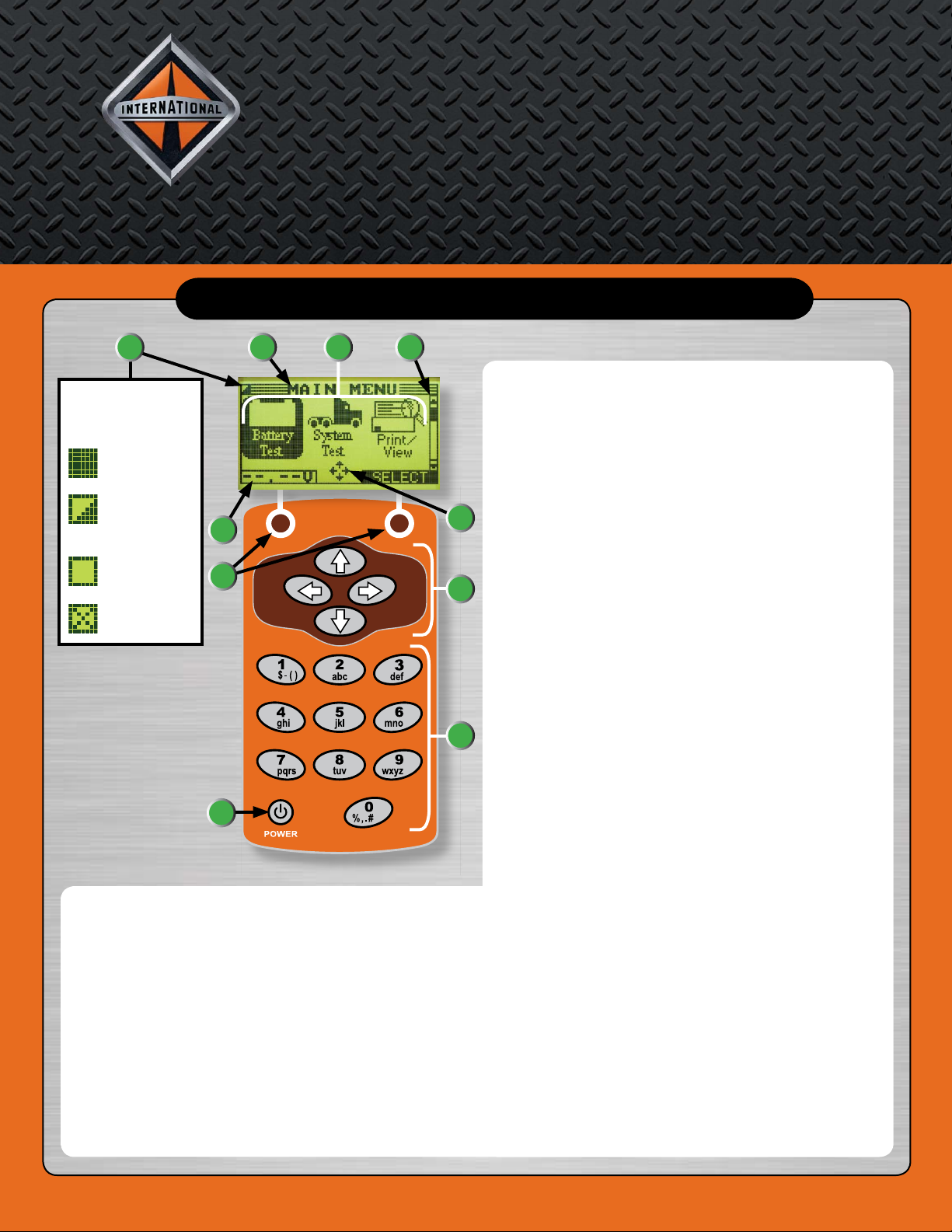
Internal battery indicator
shows power level and
status.
1. Status Indicator: Internal Batteries
This indicator appears in the screen’s top left corner. It
provides the status and charge level of the tester’s six
1.5 AA volt batteries.
2. Title Bar
The Title Bar shows the name of the current menu, test
tool, utility, or function.
3. Selection Area
The Selection Area below the Title Bar contains items
for selection or into which you enter information. The
area also displays instructions and warnings.
A N AV I S TA R C O M PA N Y
Quick Reference Guide for
International®Electrical System Tester
If you require further assistance in using
the International®Electrical System Tester, contact Midtronics at: 1-800-776-1995.
©2007 International Truck and Engine Corporation
Printed in the United States of America
TMT-080702
4. Scroll Bar
A navigational aid on the right side of the screen. The
position of its scroll box shows whether the screen is
the top (or only screen), middle, or last in a series.
5. Directional Arrows
When displayed in menu screens, the Directional
Arrows show which ARROW key on the keypad to
press to display other icons or screens. The Up and
Down Directional Arrows show when to press the
UP and DOWN ARROW keys to display the screens
above and below the current screen. The Left and Right
Directional Arrows show when to use the LEFT or
RIGHT ARROW keys to select an icon.
6. Keypad Arrows
The Keypad Arrows are used to log on, navigate to
menus and options, customize settings, and perform
tests.
7. Alphanumeric Keypad
The Alphanumeric Keypad is used to enter numerical
test parameters instead of scrolling to them with the
ARROW keys.
8. POWER Button
Press the POWER button to turn the tester on and off.
The tester also turns on automatically when connected
to a battery.
9. Soft Keys
Press the two Soft Keys linked to the bottom of the
screen to perform the functions displayed above them.
The functions change depending on the menu or test
process. Some of the more common soft-key functions
are SELECT, BACK, and EXIT.
10. Voltmeter
When first connected to a battery, the tester functions
as a voltmeter. The voltage reading appears above the
left soft key until you move to other menus or functions.
DISPLAY AND KEYPAD
The Utilities Menu allows you customize the tester. Before testing, check the default values
to see which options you may want to change.
Clock
Settings to adjust date
and time.
Users
Add, edit, or delete User IDs
(up to twenty four) using a maximum
of seven alphanumeric characters.
Shop
Allows you to add a
custom header to printed
test results.
Display
Settings to adjust the screen
contrast and backlight time.
Coupon
If you’ve created a coupon in
the Edit Coupon utility, use
Coupon to enable or disable.
Edit Coupon
Allows you to create and
store up to three separate
coupons to be printed on
test results.
Temp
Allows you to select degrees
in C or F for temperature
measurements.
Language
Sets the language of the
display and printouts.
Format
Formats the SD card to
receive data. Also erases
all data on the card.
Update
Updates the tester
software via files on an
SD card.
Screen Dump
Allows for sending the
screen image from the
tester to the EZ-Tech®.
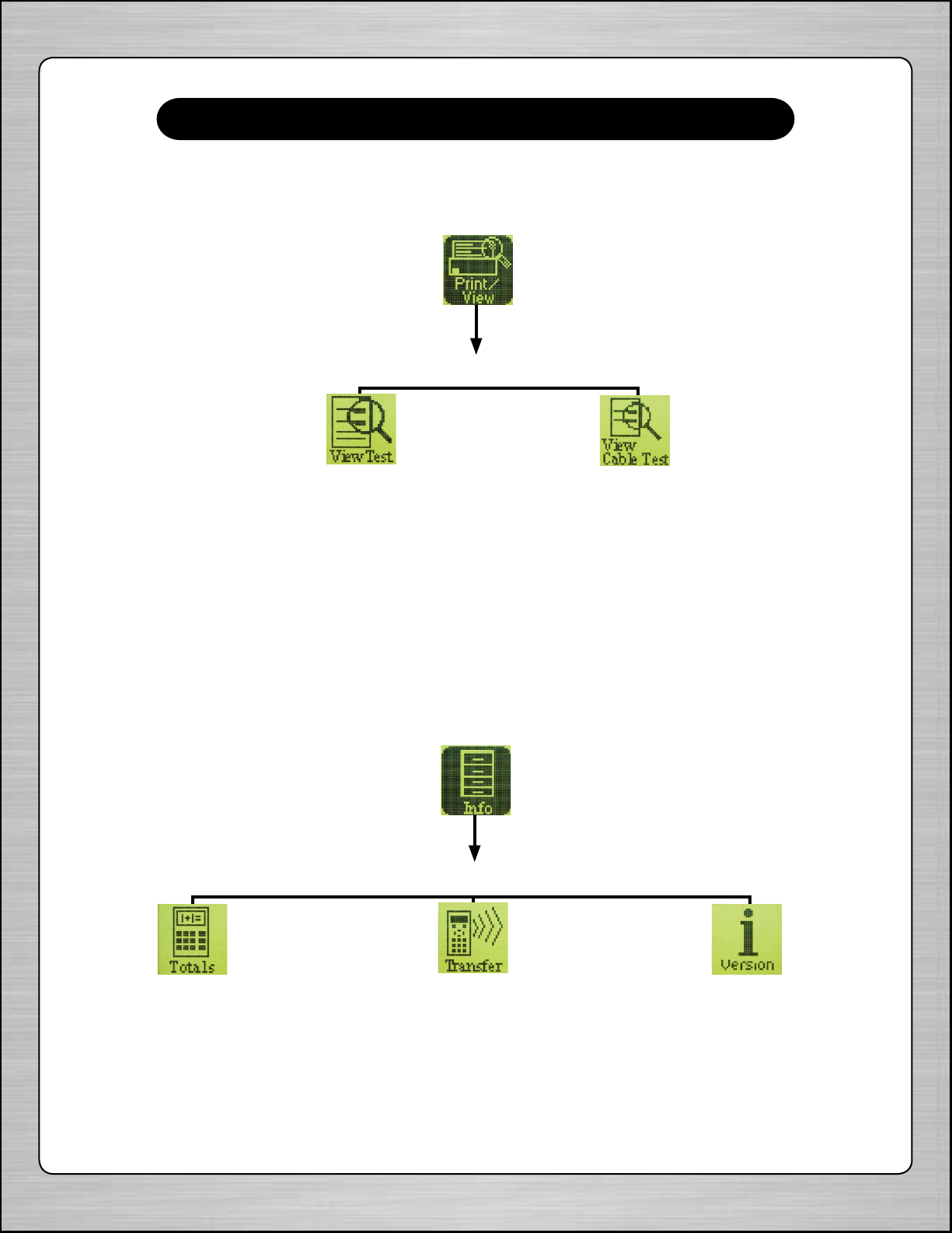
SETUP (Screen 1)
SETUP (Screen 2)
SETUP (Screen 3)
SETUP (Screen 4)
®
1
10
23
5
4
9
8
6
7
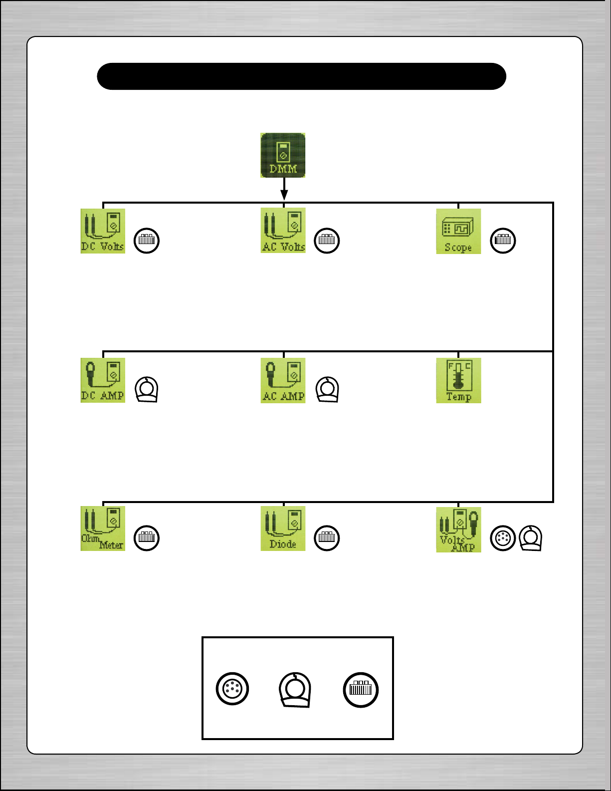
UTILITY MENU
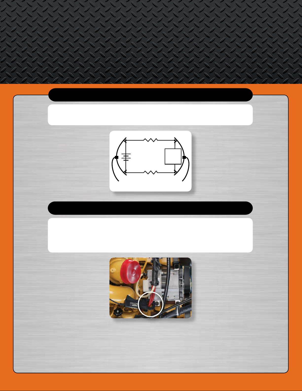
CABLE DROP TEST
AMP CLAMP
When performing the Charging System test, it is recommended that you
use the amp clamp provided with the International®Electrical System Tester
kit. Prior to performing the test, place the amp clamp around the positive
alternator cable as shown in the illustration below.
The Cable Drop Test requires two test lead connections, as shown in the
illustration below.
R
Battery
Battery Test Lead
DMM Test Lead
Component
Under
Test
1
2
R
+
–
Red Red
Black Black