manuals.online logo
Brands
  1. Home
  2. •
  3. Brands
  4. •
  5. Navitar
  6. •
  7. Lens
  8. •
  9. Navitar 1-17766 User manual

Navitar 1-17766 User manual

Telecentric Lenses
• Zoom telecentric system.
• Single-Sided telecentric lenses.
• Single-Sided telecentric accessories.
• Video telecentric lenses.
• Double-Sided telecentric lenses.
• Double-Sided telecentric illumination accessories.
Telecentric Lenses
Telecentric Lenses
90
http://machinevision.navitar.com • email: [email protected]
Telecentric Lenses
Navitar Telecentric Lenses
Navitar o ers a family of high-performance telecentric lenses for use in
machine vision, metrology and precision gauging applications. All provide low
optical distortion and a high degree of telecentricity for maximum, accurate im-
age reproduction, particularly when viewing three-dimensional objects.
Bene ts of Telecentric Lenses
One of the most important bene ts of a telecentric lens is that image magni ca-
tion does not change as object distance varies. A telecentric lens views and
displays the entire object from the same prospective angle, therefore, three-di-
mensional features will not exhibit the perspective distortion and image position
errors present when using a standard lens. Objects inside deep holes are visible
throughout the  eld, undistorted, therefore, telecentric lenses are extremely
useful for inspecting three-dimensional objects or scenes where image size and
shape accuracy are critical.
Choose the Best Lens Option for Your Needs
Our machine vision telecentric lenses include the 12X
Telecentric Zoom system, the TC-5028 and TEC-M55
telecentric video lens. Our single-sided lenses, the In-
varigon-R™, Macro Invaritar™, ELWD Macro Invaritar™
and Invaritar Large Field telecentric lenses are avail-
able with several di erent accessories that enhance
the performance of the lenses. They include telecon-
verters, right angle attachments,  ber bundle collima-
tors and lens mounting brackets. Our Double-Sided
series of lenses are telecentric in both the object and
image space and have optional illumination accesso-
ries to provide a bright, even illumination that will
compliment the performance of the lenses.
91Phone: 800-828-6778 or 585-359-4000 • Fax 585-359-4999
Telecentric Lenses
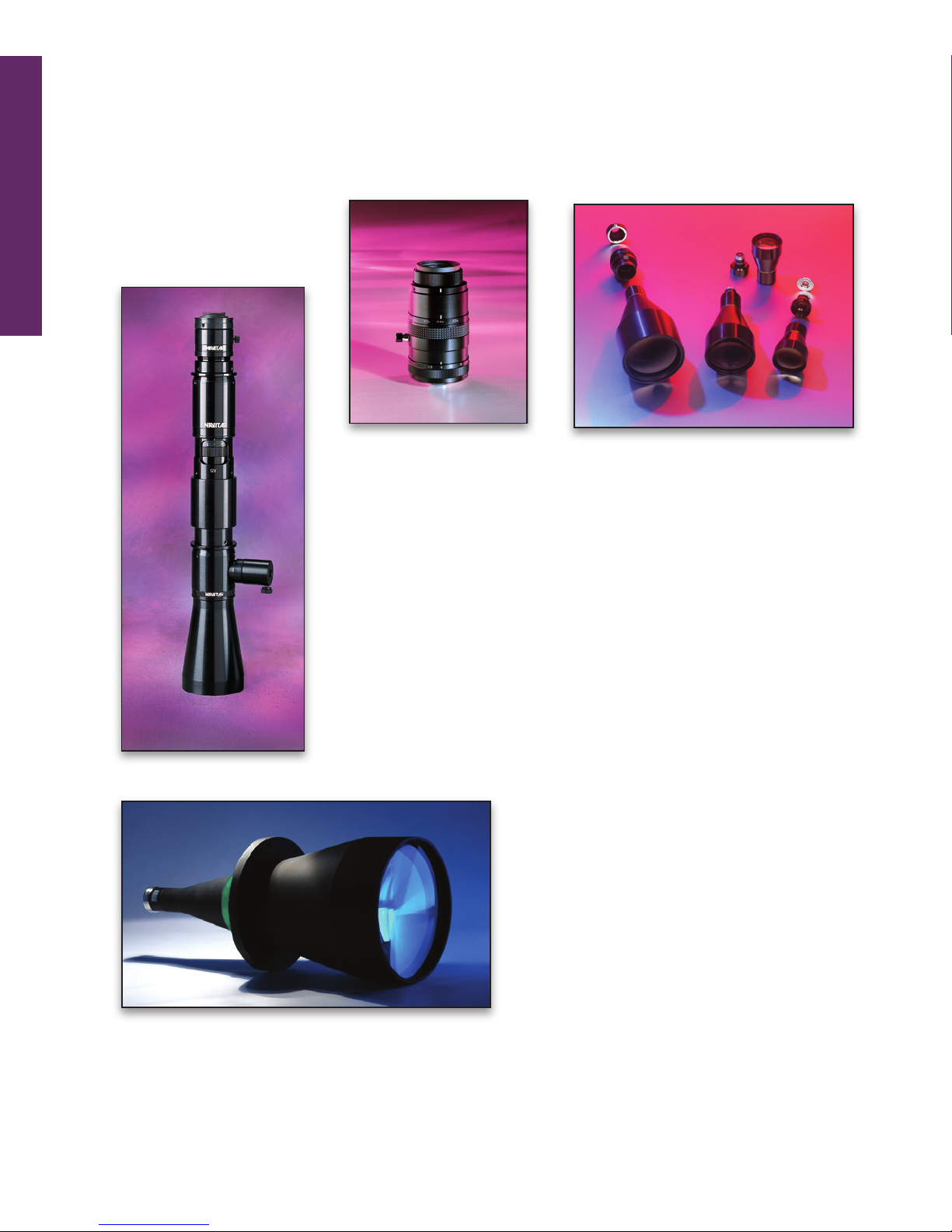
The World’s First Parfocal Telecentric Zoom Lens
The 12X Telecentric Zoom system allows users to reach a true telecentric
condition to within less than 0.3° while maintaining constant perspective
and magni cation. This means that even if the object is slightly out of
focus, the size of the image will not change. The 12X Telecentric Zoom
provides  eld coverage from 50 mm down to 4 mm and the coaxial illumi-
nation allows clear viewing, even when working with mirror-like surfaces.
Also available without coaxial illumination.
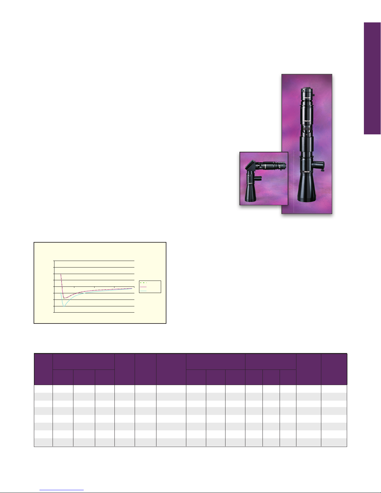
Wide Magni cation Range and Ultra Long Working Distance
In the past, a telecentric lens was de ned as having  xed magni ca-
tion. Not anymore! The Navitar 12X Telecentric Zoom lens allows you
to zoom in and focus over a wide variety of magni cations with a higher
level of accuracy than you ever thought possible. The 12X Telecentric
Zoom provides adjustable focal lengths over a 0.16X to 1.94X magni ca-
tion range. You no longer have to be limited by telecentric lenses that
only o er  xed magni cation. Now you have  eld coverage from 50 mm
down to 4 mm at a 188 mm working distance.
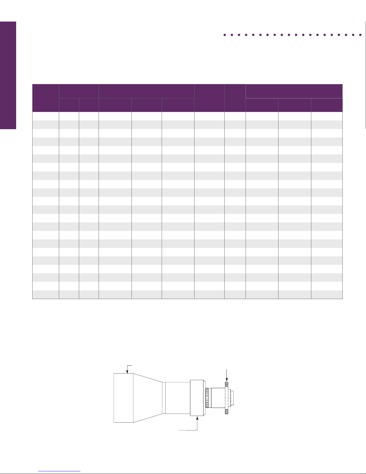
Zoom Telecentric System
12X Telecentric Accuracy
Telecentric Error Over Depth
-0.04
-0.03
-0.02
-0.01
0
0.01
0.02
0.03
0.04
0.00 0.50 1.00 1.50 2.00
1/4" format
1/3" format
1/2" format
Telecentric Error
(degrees) Object
N.A.
Image
N.A.
Object
Depth of
Focus
(mm)
Telecentric Error
(mm) Object Size Approx.
MTF
(Ip/mm)
Resolvable
Features
(microns)
Mag. 1/4” 1/3” 1/2” 1/4” 1/3” 1/2” 1/4” 1/3” 1/2”
0.16 0.05 0.06 -0.03 0.005 0.032 38.8 0.018 0.020 -0.009 25.0 37.3 49.7 15 33
0.23 -0.10 -0.09 -0.18 0.007 0.031 19.4 -0.017 -0.016 -0.030 17.4 26.1 34.8 22 23
0.33 -0.19 -0.18 -0.27 0.010 0.030 10.3 -0.016 -0.016 -0.024 12.1 18.2 24.3 30 17
0.47 -0.23 -0.23 -0.31 0.013 0.028 6.0 -0.012 -0.012 -0.016 8.5 12.8 17.0 39 13
0.67 -0.25 -0.25 -0.34 0.016 0.024 3.8 -0.008 -0.008 -0.011 5.9 8.9 11.9 49 10
0.96 -0.27 -0.27 -0.36 0.020 0.021 2.6 -0.006 -0.006 -0.008 4.2 6.3 8.4 59 8
1.36 -0.29 -0.29 -0.38 0.024 0.017 1.8 -0.004 -0.005 -0.006 2.9 4.4 5.9 71 7
1.94 -0.25 -0.24 -0.29 -0.028 0.015 1.3 -0.003 -0.003 -0.003 2.1 3.1 4.1 84 6
Distortion < 0.1% for all magni cations. Working Distance = 188 mm for all magni cations.
12X Telecentric Lens Speci cations
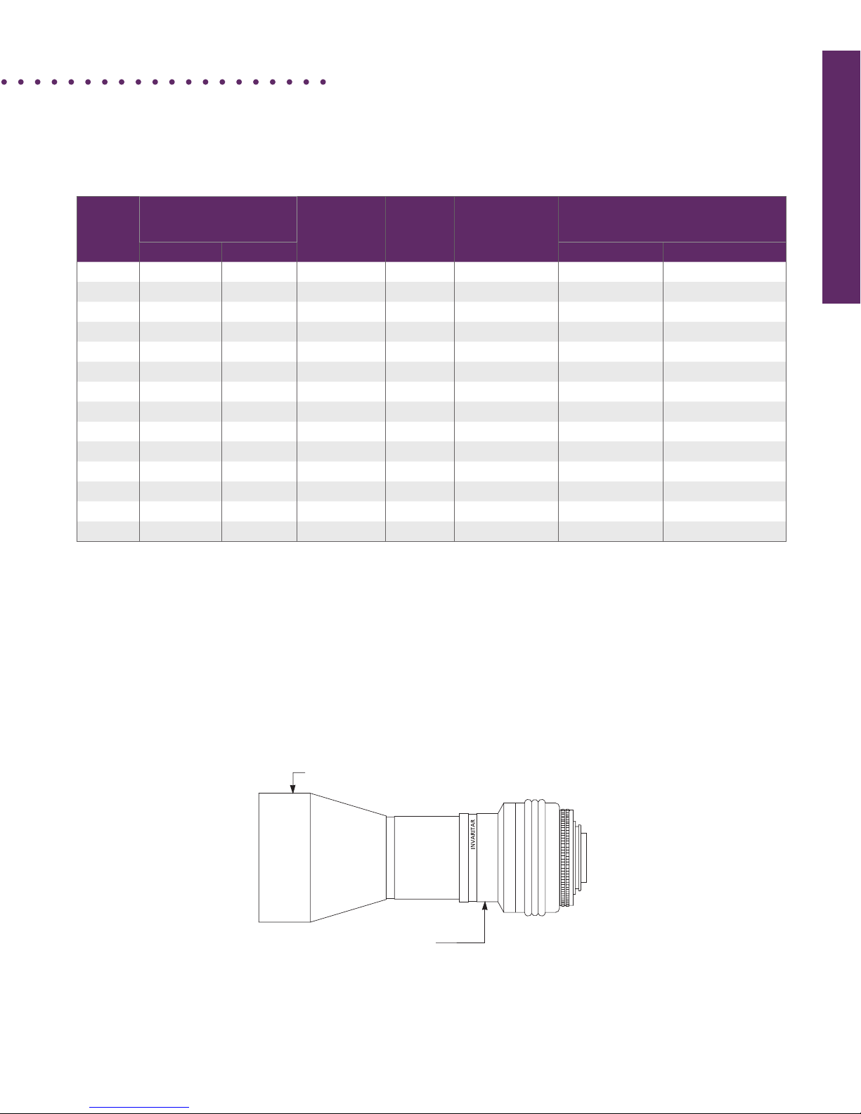
No Need to Change Lenses
The easily adjustable  eld of view and magni cation allow
our Navitar 12X Telecentric lens to adjust to meet your
exact requirements. It’s no longer necessary to change
lenses, mix and match base lenses with attachment lenses
or recalibrate. One lens, the 12X Telecentric, really does
it all! Straight, as well as right angle, versions allow OEM
designers to best  t the systems to their mechanical design.
Wide Range of Applications
Speci cally designed for precise dimensional measurement
of objects or pattern recognition, the 12X Telecentric Zoom
has many applications. It’s ideal for measuring three-di-
mensional objects with deep features, such as well plates,
electrical connector pins, and other precision parts. It’s
also the perfect lens for viewing inconsistently placed parts
on a conveyer belt.
Telecentric Lenses
92
http://machinevision.navitar.com • email: [email protected]
working
distance
diameter
f53.6 (2.11)
4.0 (.16)
f29.5 (1.16)
1-32 UNF (C-mount)
clamp in this area
INVARIGON P/N LGU
length
dimensions in mm (in.)
1The maximum object dimensions shown in the table are 90% of the theoretical maximum dimensions, providing a safety factor for magni cation and alignment errors.
2 Image-side working f/# with lens aperture fully open. For combinations with teleconverters, the minimum image-side f-number is increased by the teleconverter
magni cation.
3Lenses operated at smaller f/# may show reduced resolution, especially near the edge of the  eld of view.
4Depth of  eld is calculated at f/11 for lenses with minimum operating f/# < f/16 (f/22 for all others) and for 30-µm allowable blur at the image (camera) plane.
Note: Distortion is less than 1.2% for all lenses. Contact Navitar for speci c
distortion characteristics for a particular lens.
Single-Sided Telecentric
Part Number Mag.
(nominal) Length Diameter
Working
Distance Maximum Object Dimensions (in)1Min f#2
Min.
Operating
f#3
Depth of
Field
(in.)4
mm. in. mm. in. mm. in. 1/3” CCD 1/2” CCD 2/3”CCD
59 LGU 013 0.13X 217 8.5 80 3.2 190 7.4 1.02 x 1.36 1.36 x 1.81 N/A 1.4 4 1.66
59 LGU 016 0.16X 176 6.9 70 2.8 150 6.0 0.82 x 1.09 1.09 x 1.45 N/A 1.4 5.6 1.06
59 LGU 018 0.18X 154 6.1 61 2.4 130 5.2 0.71 x 0.95 0.95 x 1.27 N/A 1.4 5.6 0.81
59 LGU 022 0.22X 170 6.7 70 2.8 150 6.0 0.59 x 0.78 0.78 x 1.04 1.07 x 1.43 1.6 8 0.54
59 LGU 025 0.25X 148 5.8 61 2.4 130 5.2 0.51 x 0.68 0.68 x 0.91 0.94 x 1.25 1.6 8 0.42
59 LGU 029 0.29X 126 4.9 54 2.1 110 4.4 0.44 x 0.59 0.58 x 0.78 0.80 x 1.07 1.6 8 0.31
59 LGU 031 0.31X 171 6.7 70 2.8 150 6.0 0.41 x 0.54 0.54 x 0.72 0.74 x 0.99 2.3 8 0.27
59 LGU 036 0.36X 149 5.9 61 2.4 130 5.2 0.36 x 0.47 0.48 x 0.63 0.66 x 0.87 2.3 8 0.20
59 LGU 042 0.42X 126 5.0 54 2.1 110 4.4 0.31 x 0.41 0.41 x 0.54 0.56 x 0.74 2.3 8 0.15
59 LGU 050 0.50X 10⁵ 4.1 54 2.1 90 3.6 0.26 x 0.34 0.34 x 0.45 0.47 x 0.62 2.3 11 0.10
Telecentric performance (<0.2° chief ray angle over
the entire object  eld) allows precise gauging of
3-dimensional objects.
•
Large selection of magni cations covers most applications.
• Lockable aperture adjusts to select the required
depth of  eld.
• Fine focus adjustment provides sharper images.
Rugged single-piece design stands up to harsh •
industrial environments.
High-performance multi-layer coatings provide the• high-
est image clarity, especially for back-lit applications.
Standard C-mount camera interface. •
Features
The Invarigon-R™ family of gauging lenses provides telecentric imaging with a wide selection of magni cations.
Invarigon-R™
gauging lenses are the most cost-e ective choice for critical inspection and metrology imaging applications.
Invarigon-R™ Lens Speci cations
Invarigon-R™
Teleconverter accessories
can be used with select
Invarigon-R™ lenses (59 LGU 031, 59 LGU 036,
59 LGU 042, 59 LGU 050) to increase magni cation by
a factor of 1.5x or 2.0x depending on the lens combina-
tion. Teleconverters cannot be used with certain types of
3-CCD color cameras.
Accessory Note:
93Phone: 800-828-6778 or 585-359-4000 • Fax 585-359-4999
Telecentric Lenses
Single-Sided Telecentric
Features
Telecentric performance (<0.25° chief ray •
angle over the entire object  eld) allows pre-
cise gauging of 3-dimensional objects.
Low distortion (<0.1% over the entire object •
 eld) provides highly accurate images.
Small footprint to  t into restricted spaces. •
Rugged single-piece design stands up to harsh •
industrial environments.
Lockable aperture adjusts to select the required •
depth of  eld.
Standard C-mount camera interface. •
The Macro Invaritar™ telecentric gauging lenses provide exceptional telecentric imaging performance and are the best
choice for machine vision applications involving signi cant space limitations.
Part
Number
Mag.1
(nominal)
Length Diameter Working Dist. Maximum Object Dimensions (mm.)2f# Range3
Depth of
Field
(mm)4
mm. inches mm. inches mm. inches 1/3” CCD 1/2” CCD 2/3”CCD
59 LGM 205 0.05X 10⁴ 4.1 42 1.7 48 1.9 6.5 x 8.6 8.6 x 11.5 11.9 x 15.8 12 - 32 3.84
59 LGM 601 1x 110 4.3 32 1.2 46 1.8 3.2 x 4.3 4.3 x 5.8 5.9 x 7.9 6.25 - 32 1.92
59 LGM 602 2x 10⁷ 4.2 32 1.2 25 1.0 1.6 x 2.2 2.2 x 2.9 3.0 x 4.0 3.12 - 16 0.48
59 LGM 605 5x 175 6.9 41 1.6 36 1.4 0.6 x 0.9 0.9 x 1.2 1.2 x 1.6 2.5 - 8 0.10
1Tolerance on speci ed magni cation is ±3%.
2The maximum object dimensions shown in the table are 90% of the theoretical maximum dimensions, providing a safety factor
for magni cation and alignment errors.
3ƒ/# speci ed in object space.
4Depth of  eld is calculated at largest available for each lens ƒ/# and for a 30-µm allowable blur at the image (camera).
Macro Invaritar™ Lens Speci cations
Macro Invaritar™
Telecentric performance (<0.2° chief ray angle over
the entire object  eld) allows precise gauging of
3-dimensional objects.
•
Large selection of magni cations covers most applications.
• Lockable aperture adjusts to select the required
depth of  eld.
• Fine focus adjustment provides sharper images.
Rugged single-piece design stands up to harsh •
industrial environments.
High-performance multi-layer coatings provide the• high-
est image clarity, especially for back-lit applications.
Standard C-mount camera interface. •
Features
diameter
6.25 8 1116 22
working
distance
1-32 UNF (C mount)
3.5 (.14)
length
dimensions in mm (in.)
Telecentric Lenses
94
http://machinevision.navitar.com • email: [email protected]
Features
Telecentric performance (<0.1° chief ray •
angle over the entire object  eld) allows pre-
cise gauging of 3-dimensional objects.
Low distortion (<0.5% over the entire object •
 eld) provides highly accurate images.
Long working distance permits convenient •
mounting.
Rugged single-piece design stands up to harsh •
industrial environments.
Lockable aperture adjusts to select the required •
depth of  eld.
Standard C-mount camera interface. •
Single-Sided Telecentric
Part Number Mag.
(nominal)
Length WD. Maximum Object Dimensions (mm.)1f#
Range2
Depth of
Field
(mm.)3
mm. inches mm. inches 1/3” CCD 1/2” CCD 2/3”CCD
59 LGN 702 2x 186 7.3 116 4.5 1.6 x 2.2 2.2 x 2.9 3.0 x 4.0 5.6 - 16 0.48
59 LGN 703 3x 256 10.1 105 4.1 1.1 x 1.4 1.4 x 1.9 2.0 x 2.6 5.6 - 16 0.32
59 LGN 704 4x 303 11.9 101 4.0 0.8 x 1.1 1.1 x 1.4 1.5 x 2.0 5.6 - 16 0.24
59 LGN 705 5x 362 14.2 98 3.9 0.6 x 0.9 0.9 x 1.2 1.2 x 1.6 5.6 - 16 0.19
1The maximum object dimensions shown in the table are 90% of the theoretical maximum dimensions, providing a safety factor for magni cation and
alignment errors.
2ƒ/# speci ed in object space.
3Depth of  eld is calculated at largest available for each lens ƒ/# and for a 30-µm allowable blur at the image (camera).
ELWD Macro Invaritar Speci cations
ELWD Macro Invaritar™
ELWD (Extra-Long Working Distance) Macro Invaritar™ telecentric gauging lenses provide exceptional imaging
performance and are the best choice for machine vision applications where an extra-long working distance is
required.
M52!0.75 thread (internal)
55 (2.2)
16 11 8 £/5.6
locking aperture ring
(3!M3 nylon tip set screw)
working distance length
77 (3.0) 3.2 (.12)
f 40 (1.6)
1-32 UNF (C mount)
dimensions in mm (in.)
95Phone: 800-828-6778 or 585-359-4000 • Fax 585-359-4999
Telecentric Lenses
Features
Telecentric performance of less than 0.5-degree •
chief ray angle over the entire object  eld allows
precise gauging of 3-dimensional objects.
Large selection of base and attachment lenses •
covers most applications.
Low distortion provides for highly accurate •
images.
Lockable aperture adjusts to select the re• quired
depth of  eld.
C-mount lenses include  ne focus adjust• ment,
providing sharper images.
High-performance multi-layer coatings pro• vide
the highest image clarity, especially for backlit
applications.
Both C-mount and F-mount base lenses are• available.
F-mount Base Lenses
Attachment Lenses
Single-Sided Telecentric
Invaritar™ modular, large- eld telecentric gauging lenses provide a wide range of solutions for a variety of machine
vision applications. A telecentric lens system is created by combining a base lens with an appropriate attachment
lens to achieve the required magni cation and  eld of view.
diameter
length
attachment lens
F-mount base lens
Part Number Length Diameter Weight
mm. inches mm. inches kg. lb.
59 LGC 516 55 2.2 52 2.1 0.15 0.32
59 LGG 925 53 2.1 30 1.2 0.08 0.17
59 LGG 935 46 1.8 30 1.2 0.08 0.17
59 LGG 950 55 2.2 30 1.2 0.08 0.17
C-mount Base Lenses
Part Number Length Diameter Weight
mm. inches mm. inches kg. lb.
59 LGH 416 121 4.8 84 3.3 0.64 1.40
59 LGJ 423 206 8.1 121 4.8 1.76 3.87
59 LGL 428 269 10.6 150 5.9 4.00 8.80
59 LGH 431 275 10.8 84 3.3 0.81 1.78
Part Number Length Diameter Weight
mm. inches mm. inches kg. lb.
59 LGB 435 74 2.9 76 3.0 0.04 0.9
59 LGB 450 57 2.2 76 3.0 0.04 0.8
59 LGB 485 68 2.7 82 3.2 0.06 1.3
59 LGB 499 117 4.6 85 3.3 0.08 1.8
Invaritar™ Large Field
attachment lens
C-mount base lens
optional
teleconverte
r
Telecentric Lenses
96
http://machinevision.navitar.com • email: [email protected]
C-mount Invaritar™ Large-Field Telecentric Lens Specications
(for camera formats less than or equal to 2/3”)
Mag.
(nominal)
Working
Distance Maximum Object Dimensions (mm.)1Minimum
Operating
F# Range2
Depth
of
Field
(in)3
Part Numbers
for Required Optical Components
mm. inches 1/3” CCD 1/2” CCD 2/3”CCD Base Lens Attach.
Lens
Tele-
converter 4
0.06x 241 9.5 2.23 x 2.98 N/A N/A 2.0 7.22 59 LGC 916 59 LGL 428 none
0.07x 203 8.0 1.83 x 2.44 N/A N/A 2.8 5.0 59 LGC 916 59 LGJ 423 none
0.09x 241 9.5 1.43 X 1.90 1.90 X 2.54 2.62 X 3.49 2.0 3.21 59 LGG 925 59 LGL 428 none
0.10x 140 5.5 1.28 X 1.70 N/A N/A 5.6 2.60 59 LGC 916 59 LGH 416 none
0.11x 203 8.0 1.17 X 1.56 1.56 X 2.09 2.15 X 2.87 2.8 2.15 59 LGG 925 59 LGJ 423 none
0.11x 267 10.5 1.13 x 1.51 1.51 x 2.01 N/A 2.8 2.15 59 LGG 935 59 LGH 431 none
0.13x 241 9.5 1.02 X 1.36 1.36 X 1.81 1.87 X 2.49 2.0 1.54 59 LGG 935 59 LGL 428 none
0.15x 203 8.0 0.84 X 1.12 1.12 X 1.49 1.54 X 2.05 5.6 1.15 59 LGG 935 59 LGJ 423 none
0.16x 140 5.5 0.82 X 1.09 1.09 X 1.45 1.50 X 2.00 11.0 1.02 59 LGG 925 59 LGH 416 none
0.16x 267 10.5 0.79 X 1.06 1.06 X 1.41 1.45 X 1.94 2.8 1.02 59 LGG 950 59 LGH 431 none
0.18x 241 9.5 0.71 X 0.95 0.95 X 1.27 1.31 X 1.74 5.6 0.80 59 LGG 950 59 LGL 428 none
0.22x 140 5.5 0.58 X 0.78 0.78 X 1.04 1.07 X 1.42 11.0 0.54 59 LGG 935 59 LGH 416 none
0.22x 203 8.0 0.59 X 0.78 0.78 X 1.05 1.08 X 1.44 5.6 0.54 59 LGG 950 59 LGJ 423 none
0.24x 267 10.5 0.53 X 0.70 0.07 X 0.94 0.97 X 1.29 4.0 0.45 59 LGG 950 59 LGH 431 59 LGZ 415
0.27x 241 9.5 0.48 X 0.64 0.63 X 0.85 0.87 X 1.16 11.0 0.36 59 LGG 950 59 LGL 428 59 LGZ 415
0.31x 140 5.5 0.41 X 0.54 0.54 X 0.72 0.75 X 1.00 11.0 0.27 59 LGG 950 59 LGH 416 none
0.32x 267 10.5 0.39 X 0.53 0.53 X 0.70 0.72 X 0.97 5.6 0.25 59 LGG 950 59 LGH 431 59 LGZ 420
0.33x 203 8.0 0.39 X 0.52 0.52 X 0.70 0.72 X 0.96 5.6 0.24 59 LGG 950 59 LGH 423 59 LGZ 415
036x 241 9.5 0.36 X 0.48 0.48 X 0.64 0.66 X 0.87 16.0 0.29 59 LGG 950 59 LGL 428 59 LGZ 420
0.43x 203 8.0 0.29 X 0.39 0.39 X 0.52 0.54 X 0.72 16.0 0.20 59 LGG 950 59 LGJ 423 59 LGZ 420
0.47x 140 5.5 0.27 X 0.36 0.36 X 0.48 0.50 X 0.66 11.0 0.12 59 LGG 950 59 LGH 416 59 LGZ 415
0.63x 140 5.5 0.20 X 0.27 0.27 X 0.36 0.37 X 0.50 16.0 0.10 59 LGG 950 59 LGH 416 59 LGZ 420
1. The maximum object dimensions shown in the table are 90% of the theoretical maximum dimensions, providing safety factor of magnication and alignment errors.
2. Lenses operated at smaller f/# may show reduced resolution, especially near the edge of the eld of view.
3. Depth of eld is calculated for a 30-µm allowable blur at the image (camera) plane at f/11 (for lenses with minimum operating f-number<f/16) or f/22 (for all others).
4. Teleconverters 59 LGZ 420 and 59 LGZ 415 cannot be used with certain types of 3-CCD color cameras.
Note: Distortion is less than 2% for all lenses. Contact Navitar for distortion characteristics for a specic lens.
Single-Sided Telecentric
Invaritar™ Large-Field C-mount Lens
attachment lens
C-mount base lens
optional
teleconverte
r
Invaritar™ Large Field (Continued)
97Phone: 800-828-6778 or 585-359-4000 • Fax 585-359-4999
Telecentric Lenses
Mag.
(nom.) Working Distance
Maximum
Object Dimen-
sions (in.)1
Minimum
Operating
F# 2
Depth of Field
(in) 3
Part # for Required
Optical Components
mm. in. 1” CCD Base Lens Attach. Lens
0.13x 241 9.5 2.61 x 2.61 16.0 2.24 59 LGB 435 59 LGL 428
0.15x 203 8.0 2.14 X 2.14 16.0 1.68 59 LGB 435 59 LGJ 423
0.18x 241 9.5 1.83 X 1.83 16.0 1.17 59 LGB 450 59 LGL 428
0.22x 140 5.5 1.49 X 1.49 16.0 0.78 59 LGB 435 59 LGH 416
0.22x 203 8.0 1.50 X 1.50 16.0 0.78 59 LGB 450 59 LGJ 423
0.27x 267 10.5 1.19 X 1.19 2.8 0.36 59 LGB 485 59 LGH 431
0.30x 241 9.5 1.07 X 1.07 16.0 0.42 59 LGB 485 59 LGL 428
0.31x 140 5.5 0.04 X 0.04 16.0 0.39 59 LGB 450 59 LGH 416
0.32x 267 10.5 0.01 X 0.01 4.0 0.25 59 LGB 499 59 LGH 431
0.36x 241 9.5 0.91 X 0.91 16.0 0.29 59 LGB 499 59 LGL 428
0.37x 203 8.0 0.88 X 0.88 16.0 0.28 59 LGB 485 59 LGJ 423
0.43x 203 8.0 0.75 X 0.75 16.0 0.20 59 LGB 499 59 LGJ 423
0.53x 140 5.5 0.61 X 0.61 8.0 0.09 59 LGB 485 59 LGH 416
0.63x 140 5.5 0.52 X 0.52 8.0 0.07 59 LGB 499 59 LGH 416
1. The maximum object dimensions shown in the table are 90% of the theoretical maximum dimensions for a 9.2 mm x 9.2 mm (Kodak MegaPlus) format sensor;
providing a safety factor of magnication and alignment errors. For larger arrays, contact Navitar.
2. Lenses operated at smaller f/# may show reduced resolution, especially near the edge of the eld of view.
3. Depth of eld is calculated for a 30-µm allowable blur at the image (camera) plane at f/11 (for lenses with minimum operating f-number <f/16) or f/22 (for all others).
Note: Distortion is less than 2% for all lenses. Contact Navitar for distortion characteristics for a specic lens.
An accessory C-mount adaptor (59 LGT 101) is required for coupling F-mount Invaritar™ base lenses to a C-mount camera.
Single-Sided Telecentric
F-mount Invaritar™ Large-Field Telecentric Lens Specications
(for camera formats greater than 2/3”)
attachment lens
F-mount base lens
Invaritar™ Large-Field F-mount Lens
Invaritar™ Large Field (Continued)
Telecentric Lenses
98
http://machinevision.navitar.com • email: [email protected]
Single-Sided Telecentric Lens
Accessories
Teleconverters
When a closer view of objects is required, use a 59
LGZ-series teleconverter with your InvaritarTM large-
 eld gauging lens. Mounted between the lens and the
camera, these teleconverters increase magni cation by
up to 2.0×. Their compact size has minimum impact
on overall lens/camera length. Teleconverters increase
lens f-number and contribute to overall image distor-
tion. Teleconverters cannot be used with some 3-CCD
color cameras.
Navitar o ers several di erent accessories to enhance the performance of their Machine Vision telecentric lenses.
These include: teleconverters to increase magni cation, right angle attachments for viewing of objects up to 360
degrees about the optical axis,  ber bundle collimators to provide collimated backlighting and anodized mounting
brackets for proper mounting of the Invarigon-R™ and Invaritar™ lenses.
Part Number Mag. Mount Applicable
Lens F/# Change Focal Length
Change
Field of View
Change
Obj. Dimensions
Change
Length
(mm./in.)
Diameter
(mm./in.)
HE15-1 1.5X C-mount LFJ, LGC Original x 1.5 Original x 1.5 Original / 1.5 Original / 1.5 4.9/0.2 -
2XE 2.0X C-mount LFJ, LGC Original x 2.0 Original x 2.0 Original / 2.0 Original / 2.0 7.7/0.3 -
59 LGZ 814 1.4X F-mount LAF. LGB Original x 1.4 Original x 1.4 Original / 1.4 Original / 1.4 - -
59 LGZ 820 2.0X F-mount LAF. LGB Original x 2.0 Original x 2.0 Original x 2.0 Original x 2.0 36/1.4 69/2.7
Part Number Description
59 LGT 101 F-mount to C-mount Converter
Adapter
The 59 LGT 101 adapter is used to convert from the
F-mount (bayonet type) to the C-mount (1-inch, 32
TPI) thread for CCD cameras.
C-mount
(1"-32 TPI)
f58.42 (2.30)
28.65 (1.13)
C ADAPTOR -NIF-
F-mount
dimensions in mm (in.)
Teleconverter Speci cations
length
diameter
internal
F-mount
external
F-mount
dimensions in mm (inches)
teleconverter
length
C-mount
(1"-32 TPI)
f48.0 (1.89)
dimensions in mm (in.)
HE15-1/2XE teleconverters for C-mount lenses
59 LGZ 814/820 teleconverters for F-mount lenses
Features:
Rugged, chrome-plated brass construction stands •
up to harsh environments.
Multiple-element, anti-re ection coated lens •
systems provide optimum performance.
99Phone: 800-828-6778 or 585-359-4000 • Fax 585-359-4999
Telecentric Lenses
Right Angle Attachments
These attachments allow Invaritar™ lenses to view
objects at right angles to the lens axis. The telecentric-
ity, resolution, low distortion, and high contrast of the
lenses are preserved. The attachments can be rotated
360 degrees around the lens optical axis to provide
viewing in any direction.
A
(mm./in.)
B
(mm./in.)
C
(mm./in.)
D
(mm./in.)
Use with Invarigon-R
Macro Invaritar Lenses
Right Angle Attachment 59 LSF 101
33.0/1.3 15.2/0.6 144.8/5.7 121.9/4.8 59 LGM 601
Right Angle Attachment 59 LSF 401
76.2/3.0 45.7/1.8 195.6/7.7 162.6/6.4 59 LGU 042
116.8/4.6 86.4/3.4 243.8/9.6 210.8/8.3 59 LGU 050 + 59 LGZ 415
55.9/2.2 25.4/1.0 172.7/6.8 139.7/5.5 59 LGU 050
95.6/3.8 66.0/2.6 223.5/8.8 190.5/7.5 59 LGU 036 + 59 LGZ 415
116.8/4.6 86.4/3.4 246.4/9.7 213.4/8.4 59 LGU 031 + 59 LGZ 420
76.2/3.0 45.7/1.8 200.7/7.9 167.6/6.6 59 LGU 042 + 59 LGZ 415
96.5/3.8 66.0/2.6 226.1/8.9 193.0/7.6 59 LGU 036 + 59 LGZ 420
55.9/2.2 25.4/1.0 177.8/7.0 144.8/5.7 59 LGU 050 + 59 LGZ 415
76.2/3.0 45.7/1.8 203.2/8.0 170.2/6.7 59 LGU 042 + 59 LGZ 420
55.9/2.2 25.4/1.0 180.3/7.1 147.3/5.8 59 LGU 050 + 59 LGZ 420
Part Number Description
59 LSF 101 Right-Angle Attachment for Macro Invaritar Lens
Compatiable with Part Number 59 LGM 601
59 LSF 401 Right-Angle Attachment for Invarigon-R Lenses
INVARITAR 90
object
plane
C
mount
f64 (2.5)
M4 setscrews, 3@120º apart
C
D
A
Blens
dimensions in mm (in.)
Right Angle Attachments
Macro Invaritar & Invarigon Lenses with
Right Angle Attachments
Additional information and product
speci cations for telecentric lenses
available at machinevision.navitar.com
Accessories Continued
Applications
These attachments are useful whenever it is dif-
 cult to point a lens directly at the object. They
are especially helpful when adapting new optics
to existing equipment, where space is limited.
Restrictions
Right angle attachments are only usable only •
with speci ed lenses.
Combined working distance is less than with •
lens alone.
Right Angle Attachment Speci cations
Telecentric Lenses
100
http://machinevision.navitar.com • email: [email protected]
Fiber Bundle Collimator
This unit provides a large collimated beam for lighting
machine vision applications. It accepts the output
from a standard 59 QLS 700  ber optic bundle. The
uniform, collimated beam is useful for back lighting
objects for gaging and feature inspection. The spectral
content of the light is controlled by  ltering at the
 ber optic light source.
To make precise machine vision measurements,
correct lighting is essential. Back lighting is use-
ful for measuring the exterior dimension of opaque
objects, or to measure the dimensions of holes
through opaque objects. With di use back lighting,
rays from the edges of the  eld can re ect from the
edge of the object and confuse the image. A colli-
mated light source eliminates the confusing rays. This is
especially important when the object being measured
is smooth, shiny or round.
Features
Large clear aperture •
Compatible with 59 QLS 700 •
Low divergence angle •
Speci cations
Length: 190 mm •
Diameter: 53 mm •
Fiber input: 10 mm diameter •
Clear aperture: 35 mm •
Divergence angle: 11 arc min •
Part Number Description
59 LGQ 035 Fiber Bundle Collimator
190 (7.5)
f53 (2.1)
10 (0.4)
fiber optic bundle
dimensions in mm (inches)
Single-Sided Telecentric Lens
Accessories
Dimensions in mm (inches)
Fiber Bundle Collimator
59 LGQ 035 Outline Drawing & Dimensions
101Phone: 800-828-6778 or 585-359-4000 • Fax 585-359-4999
Telecentric Lenses
C
fB
fA
D clamp screw
E
2!F tapped holes
Lens Mounting Brackets
Use these brackets to clamp the Invaritar™ and
Invarigon-R™ lenses to your application. This
accessory clamps directly around the lens barrel
and includes convenient standard-sized tapped
mounting holes. The 59 LGP 717 is similar to the
59 LGP 403 and 59 LGP 414 except that it was
designed for use with the 59 LGN series Extra Long
Working Distance Macro Invaritar™ lenses.
Part Number Description A (mm./in.) B (mm./in.) C (mm./in.) Thread D E (mm./in.) Thread F
59 LGP 403 Standard Mounting Bracket 76.2 / 3.0 53.3 / 2.1 33.0 / 1.3 10-32 20.3 / 0.8 1/4 - 20
59 LGP 414 Mounting Bracket for Macro Invaritar 57.1 / 2.3 33.0 / 1.3 27.9 / 1.1 10-32 12.7 / 0.5 1/4 - 20
59 LGP 717 Mounting Bracket for ELWD Lenses 66.0 / 2.6 40.6 / 1.6 27.9 / 1.1 M6 22.9 / 0.9 M6
Note: Clamping around the barrel immediately
over the front lens element is not recommended.
If mounting larger sized Invaritar base/attachment
lens combinations, two clamps are recommended.
Features
Clamps directly around lens barrel diam-•
eter for rigid attachment
Rugged anodized-alumium construction•
M6 or 1/4-20 tapped mounting holes•
Additional information and product speci cations for
telecentric lenses available at machinevision.navitar.com
Lens Mounting Bracket Speci cations
Accessories Continued
Telecentric Lenses
102
http://machinevision.navitar.com • email: [email protected]
Video Telecentric Lenses
TC-5028
The Navitar TC-5028 telecentric lens is a 50 mm
F/2.8 telecentric lens which reduces or eliminates
viewing angle error and magni cation error while
providing high resolution and contrast with low
distortion. This compact, lightweight lens can be
used with 1/3”, 1/2” and 2/3” format cameras and is
usable from 0.5X to 1.0X, 1:1.
Speci cations for Telecentric Use
Magni cations 0.5 1.0X
Distortion at 0.5X -0.3%
Distortion at 1.0X Less than - 0.1%
Distance from Front
Lens to Object
0.5X:115mm
1.0X:85mm
TC-5028 Video Lens Speci cations
Part Number TC-5028
Focal Length 50 mm
Iris Range/ F-Stop 2.8 - Close
Control
Iris Manual
Focus Manual
Zoom N/A
Object Area
at M.O.D
(HxV)
2/3” 8.1 x 6.1
1/2” 5.9 x 4.4
1/3” 3.8 x 3.3
1/4” 2.9 x 2.2
Focusing Range (meters) 0.5 - in nity
Field Angle
(HxV)
2/3” 10º 03’ x 7º 33’
1/2” 7º 19’ x 5º 29’
1/3” 5º 29’ x 4º 07’
1/4” 3º 39’ x 2º 45’
Back Focal Length (mm) 32.5
Filter Diameter Ø37 P=0.75
Mount C-mount
Weight (grams) 318
Exit Pupil Position 48.1(from image plane)
Distortion in TV Less than 0.1%
Vignetting 97%
Filter Size M37 P0.75
TC-5028 Outline Drawing
with Dimensions
103Phone: 800-828-6778 or 585-359-4000 • Fax 585-359-4999
Telecentric Lenses
TEC-M55
Navitar also o ers the TEC-M55 telecentric C-mount
lens for 2/3” format cameras. This 55 mm F/2.8
telecentric lens maintains constant perspective and
magni cation.
Conventional lenses are often unable to accurately
portray objects which are slightly out of focus or at
di erent distances from the lens. Constant perspective
and magni cation are maintained with a telecentric
lens, so the size of the image will not change.
TEC-M55 Outline Drawing
with Dimensions
Video Telecentric Lenses
Additional information and product
speci cations for telecentric lenses
available at machinevision.navitar.com
TEC-M55 Video Lens Speci cations
Part Number TEC-M55
Focal Length 55 mm
Iris Range/ F-Stop 2.8 - 32C
Control
Iris Manual
Focus Manual
Zoom N/A
Object Area at
M.O.D (HxV) 2/3” 17 x 13
Focusing Range (meters) 0.14 - in nity
Field Angle (HxV) 2/3” 9.2º’ x 6.97º
Back Focal Length (mm) 29.8
Filter Diameter Ø43 P=0.75
Mount C-mount
Weight (grams) 320
Exit Pupil Position 30.3 (from image plane)
Telecentric Lenses
104
http://machinevision.navitar.com • email: [email protected]
Double-Sided Telecentric Lenses
Object and Image Side Telecentricity
Navitar’s Double-Sided Telecentric series of lenses
are telecentric in both the object and image space,
not just the object space as in the design of a normal
telecentric lens. This design allows for telecentricity of
less than 0.1% within the depth of  eld.
CCD and CMOS sensors continue to be developed
with smaller and smaller pixels while increased elec-
tronic circuitry within the pixel further reduces the
“ ll factor.” To help focus light onto individual pixels,
camera makers are using micro lens arrays in their de-
signs. While these individual lenses, over each pixel,
serve to collect light, they also pose a challenge to the
optics designer. These micro lenses are most e ective
when the incoming rays are  ve degrees or less, of
normal. The telecentric cone of light is a major bene t
in these situations.
Low Distortion, High Accuracy
Double-Sided Telecentric lenses are less prone to
optical aberrations and geometrical distortions. Image
sizes will not vary across the  eld due to positioning
of the sensor. Gauging applications will bene t from
a double-sided telecentric lens compared to a simple
object side only telecentric system. Our lenses are
designed to work with CCD and CMOS sensors up to
28.7mm diagonal. We o er lenses with magni cation
from 0.03X to 2.0X as well as large format lenses with
magni cation from 0.239X to 0.478X.
Mounting Options
The back focal length is adjusted on the basis of
C-mount or F-mount standard. A spacer kit with
instructions to  ne tune the back focus for a speci c
need is included with each lens. Please call for
mounting options.
Sample Product Speci cation Sheet
Telecentric both in the object and in the •
image space.
Less than 0.1% image distortion within •
the  eld depth at the  eld corners.
No image vignetting. •
No parallax error. •
No change of magni cation within the •
depth of  eld.
MTF greater than 40% at 130 lines/mm. •
Uniform illumination. •
C or F mounts available. •
Specially designed illumination accessories.•
Advantages of Double-Sided Telecentric Lenses
105Phone: 800-828-6778 or 585-359-4000 • Fax 585-359-4999
Telecentric Lenses
Part
Number
Object Field1 (mm) Optical Specications Dimensions
Mag.
(x)
1/3”
wxh
4.8 x3.6
1/2”
wxh
6.4 x 4.8
2/3”
wxh
8.8 x 6.6
WD2
(mm) F/#3
MTF@
70lp/
mm%
Field
Depth4Telecent.5Distortion
(%) Mount Length6Diam.
1-17796 2.00 2.4 x 1.8 3.2 x 2.4 4.4 x 3.3 57.1 11 > 30 0.2 < 0.08 < 0.08 C101.4 28
1-17797 1.33 3.6 x 2.7 4.8 x 3.6 6.6 x 5.0 61.2 11 > 30 0.5 < 0.08 < 0.08 C78.5 28
1-17798 1.00 4.8 x 3.6 6.4 x 4.8 8.8 x 6.6 63.3 11 > 25 1 < 0.08 < 0.08 C65 28
1-17800 0.40 12.0 x 9.0 16.0 x 12.0 diam = 16.5 45.3 8 > 40 4.5 < 0.1 < 0.08 C92 37.8
1-17801 0.55 8.7 x 6.5 11.0 x 8.7 16.0 x 12.0 45.3 8 > 30 3 < 0.1 < 0.07 C112 37.8
1-17802 0.27 18.0 x 13.5 24.0 x 18.0 diam = 24.8 69.2 8 > 45 10 < 0.1 < 0.08 C122.5 44
1-17803 0.37 13.1 x 9.8 17.5 x 13.1 24.0 x 18.0 63.4 8 > 45 7 < 0.1 < 0.1 C142 44
1-17804 0.13 36.0 x 27.0 diam = 36.0 n.a. 103.5 8 > 50 38 < 0.08 < 0.08 C133 61
1-17805 0.18 27.0 x 20.3 36.0 x 27.0 diam = 37.1 103.5 8 > 40 22 < 0.08 < 0.1 C148 61
1-17806 0.24 19.6 x 14.7 26.2 x 19.6 36.0 x 27.0 103.5 8 > 40 12 < 0.08 < 0.1 C164.9 61
1-17808 0.13 36. 0 x 27.0 48.0 x 36.0 diam = 49.5 134 8 > 40 24 < 0.1 < 0.1 C180 75
1-17809 0.18 26.2 x 19.6 34.9 x 26.2 48.0 x 36.0 134 8 > 40 14 < 0.1 < 0.1 C200 75
1-17810 0.11 42.0 x 31.5 56.0 x 42.0 diam = 57.8 159.3 8 > 50 45 < 0.08 < 0.08 C205 80
1-17811 0.16 30.5 x 22.9 40.7 x 30.5 56.0 x 42.0 159.3 8 > 45 26 < 0.08 < 0.08 C225 80
1-17812 0.08 64.0 x 48.0 diam = 64.0 n.a. 182.3 8 > 40 130 < 0.08 < 0.07 C212 100
1-17813 0.10 48.0 x 36.0 64.0 x 48.0 diam = 66.0 182.3 8 > 50 60 < 0.08 < 0.07 C227 100
1-17814 0.14 34.9 x 26.2 46.5 x 34.9 64.0 x 48.0 182.3 8 > 50 36 < 0.08 < 0.07 C245.5 100
1-17815 0.12 39.3 x 29.5 52.4 x 39.3 72.0 x 54.0 227.7 8 > 40 48 < 0.08 < 0.07 C300 120
1-17816 0.08 60.0 x 45.0 80.0 x 60.0 diam = 82.5 227.7 8 > 50 90 < 0.08 < 0.1 C272 120
1-17817 0.11 43.6 x 32.7 58.2 x 43.6 80.0 x 60.0 227.7 8 > 50 57 < 0.08 < 0.1 C272 120
1-17818 0.10 46.4 x 34.8 61.8 x 46.4 85.0 x 63.8 280.6 8 > 45 60 < 0.08 < 0.08 C346 146
1-17819 0.05 96.0 x 72.0 diam = 96.0 n.a. 280.6 8 > 50 240 < 0.08 < 0.1 C302 146
1-17820 0.07 72.0 x 54.0 96.0 x 72.0 diam = 99.0 279.6 8 > 45 120 < 0.08 < 0.08 C318 146
1-17821 0.09 52.4 x 39.3 69.8 x 52.4 96.0 x 72.0 279.6 8 > 40 70 < 0.08 < 0.08 C338 146
1-17822 0.08 60.0 x 45.0 80.0 x 60.0 110.0 x 2.5 336.5 8 > 40 90 < 0.08 < 0.07 C431 185
1-17823 0.05 90.0 x 67.5 120.0 x 90.0 diam = 123.8 336.5 8 > 45 180 < 0.08 < 0.1 C402 185
1-17824 0.07 65.5 x 49.1 87.3 x 65.5 120.0 x 90.0 336.5 8 > 35 105 < 0.08 < 0.1 C422 185
1-17825 0.07 70.9 x 53.2 94.5 x 70.9 130.0 x 97.5 398 8 > 40 150 < 0.08 < 0.1 C490 200
1-17826 0.04 108.0 x 81.0 144.0 x 108.0 diam = 148.5 398 8 > 35 260 < 0.08 < 0.08 C483 200
1-17827 0.06 78.5 x 58.9 104.7 x 78.5 144.0 x 108.0 398 8 > 40 160 < 0.08 < 0.08 C628 200
1-17828 0.05 93.8 x 70.4 125.1 x 93.8 172.0 x 129.0 531 8 > 40 240 < 0.08 < 0.1 C628 260
1-17829 0.03 144.0 x 108.0 192.0 x 144.0 diam = 198.0 531 8 > 45 360 < 0.08 < 0.08 C600 260
1-17840 0.05 104.7 x 78.5 139.6 x 104.7 192.0 x 144.0 531 8 > 35 240 < 0.08 < 0.08 C618 260
1-17841 0.04 109.1 x 81.8 145.5 x 109.1 200.0 x 150.0 500 8 > 40 310 < 0.08 < 0.1 C785 330
1-17842 0.04 130.9 x 98.2 174.5 x 130.9 240.0 x 180.0 500 8 > 45 380 < 0.08 < 0.08 C778 330
Double-Sided Telecentric Lenses for up to 2/3” Format Matrix
Part
Number Mag. (x)
Object Field1 (mm) Optical Specications Dimensions
4k x 7µm 2k x 10µm 2k x 7µm WD2
(mm) F/#3MTF@
70lp/mm%
Field
Depth4Telecen.5Distortion (%) Mount Length6Diameter
1-17843 0.478 60 43 30 230 9> 30 4 < 0.08 < 0.08 F 460 100
1-17844 0.36 80 57 40 243 9> 30 7 < 0.01 < 0.10 F 460 120
1-17845 0.239 120 86 60 250 9> 30 15 < 0.01 < 0.15 F 460 146
Large Format Double-Sided Telecentric Lenses Matrix
1For the elds with the indication “diam =” the image of a circular object is inscribed inside the short detector side.
2Working distance: Best focus front lens to object distance. Set this distance within +/- 3% of the nominal value to minimize distortion.
3Working F/#: The real F/# of a lens when used as a macro lens with a smaller aperture can be supplied upon request.
4Out of this interval the CTF contrast falls below 50% of the nominal value; the eld depth can be increased by a smaller diaphragm, available on request.
5Maximum slope of principal rays inside the lens: Turned in millirads. Tells which is the maximum measurement error for any millimeter of object displacement.
6Measured from the end of the mechanics to the camera ange.
Telecentric Lenses
106
http://machinevision.navitar.com • email: [email protected]
Double-Sided Telecentric
Illumination Accessories
Illumination has proven to be one of the most important components when designing a successful imaging system.
Navitar thoroughly understands that the correct lighting will enhance the performance of your vision system. We
oer three LED lighting options specially designed for Double-Sided Telecentric lenses. Our LED Ring Light and
Coaxial Diusive LED lighting accessories were designed for the standard working distances that most of our custom-
ers use. Collimated LED accessories are a popular choice for backlighting. All of these components are low prole
and provide bright, even illumination to compliment the performance of our lenses.
Coaxial Diusive LED Illumination
Diusive coaxial lights are designed to be used in
combination with our Double-Sided Telecentric lenses
to image objects with holes or highly reective
surfaces. The target is illuminated in the same
direction of the image capture allowing highly 3D-
shaped parts to be imaged and shadows removed.
Spectrum Illuminance at Working Distance
Part Number Window (mm)
(LxH)
Dimensions (mm)
(LxWxH)
Color K Peak wv 50mm 100mm 200mm
1-17786 50.0 x 50.0 108.0 x 57.0 x 62.0 Red - 625nm 4700 980 310
1-17787 50.0 x 50.0 108.0 x 57.0 x 62.0 White 5500 - 3300 800 250
1-17788 82.0 x 82.0 155.0 x 104.0 x 93.0 Red - 625nm 4500 910 270
1-17789 82.0 x 82.0 155.0 x 104.0 x 93.0 White 5500 - 2800 750 210
Coaxial Diusive LED Specications
Part
Number Light
Dimensions (mm)
Power Supply
Outer Diameter Lens Opening Height
1-17790 White 72 28 36 24V, 300mA
1-17791 Red 72 28 36 24V, 300mA
1-17792 White 119 61 36 24V, 600mA
1-17793 Red 119 61 36 24V, 600mA
1-17794 White 160 100 38 24V, 900mA
1-17795 Red 160 100 38 24V, 900mA
LED Ring Light Specications
LED Ring Light Illumination
Diusive LED ring lights are specically designed to t our Double-
Sided Telecentric lenses. The illuminating geometry is tailored for
the specic working distance and aperture. LED Ring Light Features:
Special mechanical interfaces. •
Dierent types of diusers. •
Available with red or white LEDs. •
External power supplies.•
Coaxial Diusive LED Features:
Built-in electronics for stability control.•
Compact design with thermal management.•
Cost-eective.•
A range of sizes to select from.•
107Phone: 800-828-6778 or 585-359-4000 • Fax 585-359-4999
Telecentric Lenses
Collimated LED Illumination
Our collimated light sources are the best choice for back lighting objects imaged through a
telecentric lens for high precision or speed applications, as all of the light exiting the collimator
enters the lens and enters the sensor.
Additional information and
product speci cations for
telecentric lenses available at
www.machinevision.navitar.com
Part Number Beam
Diameter (mm) Length (mm) Diameter (mm) LED Color
1-17765 20 87 38 White
1-17766 30 100 44 White
1-17767 45 139 61 White
1-17846 60 139 75 White
1-17768 70 191 80 White
1-17769 80 219 100 White
1-17770 100 265 116 White
1-17771 120 310 143 White
1-17772 150 396 180 White
1-17773 180 456 200 White
1-17774 250 592 260 White
1-17775 300 747 322 White
1-17776 20 87 38 Red
1-17777 30 100 44 Red
1-17764 45 139 61 Red
1-17847 60 139 75 Red
1-17778 70 191 80 Red
1-17779 80 219 100 Red
1-17780 100 265 116 Red
1-17781 120 310 143 Red
1-17782 150 396 180 Red
1-17783 180 456 200 Red
1-17784 250 592 260 Red
1-17785 300 747 322 Red
Collimated LED Speci cations
Collimated LED Features:
Eliminates border e ects that •
can warp the perceived size of
an image.
Effi cient use of light.•
LED Ring Light Coaxial Di usive LED Collimated LED
Telecentric Lenses
108
http://machinevision.navitar.com • email: [email protected]
Telecentricity FAQ’s
What is Telecentricity?
Telecentricity is a distinctive property of certain multi-element lens designs in which the chief rays
(the rays through the center of the entrance or exit pupil), for all points across the object or image, are parallel
to the optical axis.
Now, what is Telecentricity in English?
Telecentricity is all a matter of perspective distortion, which
is a variation in magnication with distance. A railroad track
that shrinks, or a tall building that gets narrower with height,
are both everyday examples of this. Hold one thumb close to
the eye and the other at arms length. One looks smaller than
the other - your brain knows that’s not so, however, a vision
system doesn’t. The telecentric lens makes all objects, within
the “depth of eld” of the lens, appear to be equidistant from
the lens, thereby eliminating the variation in magnication
with distance (see diagram at right).
What are the benets of using a Telecentric Lens?
Telecentric lenses provide constant image magnication as
object distance varies - virtually eliminating perspective angle
error. With a telecentric lens, objects inside deep holes are vis-
ible throughout the eld, undistorted, therefore, these lenses
are extremely useful for inspecting three-dimensional objects
or scenes where image size and shape accuracy are critical.
Do I need special illumination with a Telecentric lens?
Yes, if you want to derive the full benet of telecentricity. Both incident and transmitted illumination should
meet certain collimation criteria.
How is the degree of telecentricity determined?
The degree of telecentricity is measured by the chief ray angle in the corner of the eld. Telecentric lenses
have chief ray angles of less than 0.5 degrees - some even have less than 0.1 degree. In comparison, a standard
commercial lens may have chief ray angles of 10 degrees or more.
Will using a Telecentric lens improve my depth of eld?
No, telecentricity will keep the magnication constant through the depth of eld. However, the focus will
soften as with any lens. The depth of eld will still be determined by the system’s F/#.
Are Telecentric lenses available with Zoom features?
Yes, Navitar’s 12X Telecentric Zoom system allows users to reach a true telecentric condition to within less
than 0.3 degrees while maintaining constant perspective and magnication. The 12X Telecentric Zoom pro-
vides eld coverage from 50 mm down to 4 mm and with coaxial illumination, allows clear viewing, even
when working with mirror-like surfaces.
What is the dierence between a Double-Sided Telecentric lens and a standard Telecentric Lens?
Double-Sided Telecentric lenses provide both image and object side telecentricity. With the single telecentric
lens, the rays at the image plane are still coming in at strong angles. If we “double up” on the lenses, we now
have telecentric performance front and back. The resulting system is less prone to optical aberrations and geo-
metrical distortions. Image size will not vary across the eld due to positioning of the sensor.
Modern sensor pixels are both getting smaller and more cluttered up with electronic circuitry. As light collec-
tion is normally a function of active area, manufacturers are adding micro lenses over each pixel to aid in the
collection of light. These micro lenses are most eective when the incoming rays are 5 degrees, or less, o
normal. The telecentric cone of light is a major benet in these situations.
Conventional
Lens
Telecentric
Lens

This manual suits for next models

103

Other Navitar Lens manuals

Navitar 1-51315 Guide

Navitar

Navitar 1-51315 Guide

Navitar 1-62317 Guide

Navitar

Navitar 1-62317 Guide

Navitar 1-51200 Guide

Navitar

Navitar 1-51200 Guide

Navitar Zoom 6000 User manual

Navitar

Navitar Zoom 6000 User manual

Navitar 1-51196 Guide

Navitar

Navitar 1-51196 Guide

Navitar Zoom 6000 User manual

Navitar

Navitar Zoom 6000 User manual

Navitar 1-62314 Guide

Navitar

Navitar 1-62314 Guide

Navitar 1-51326 Guide

Navitar

Navitar 1-51326 Guide

Navitar 1-51206 Guide

Navitar

Navitar 1-51206 Guide

Navitar 1-51320 Guide

Navitar

Navitar 1-51320 Guide

Navitar 1-51317 Guide

Navitar

Navitar 1-51317 Guide

Navitar 1-51316 Guide

Navitar

Navitar 1-51316 Guide

Navitar 1-51210 Guide

Navitar

Navitar 1-51210 Guide

Navitar 1-51322 Guide

Navitar

Navitar 1-51322 Guide

Navitar 1-62318 Guide

Navitar

Navitar 1-62318 Guide

Navitar 1-51318 Guide

Navitar

Navitar 1-51318 Guide

Navitar 1-51319 Guide

Navitar

Navitar 1-51319 Guide

Navitar 1-62312 Guide

Navitar

Navitar 1-62312 Guide

Navitar 1-51335 Guide

Navitar

Navitar 1-51335 Guide

Navitar 12X Zoom User manual

Navitar

Navitar 12X Zoom User manual

Navitar 1-51204 Guide

Navitar

Navitar 1-51204 Guide

Navitar 1-60226 Manual

Navitar

Navitar 1-60226 Manual

Navitar 1-62308 Guide

Navitar

Navitar 1-62308 Guide

Navitar 1-51314 Guide

Navitar

Navitar 1-51314 Guide

Popular Lens manuals by other brands

BEGA 10 014 Instructions for use

BEGA

BEGA 10 014 Instructions for use

Sigma 18-200mm F3.5-6.3 II DC OS HSM instructions

Sigma

Sigma 18-200mm F3.5-6.3 II DC OS HSM instructions

FUJINON YV10x5B-SA2 Operation manual

FUJINON

FUJINON YV10x5B-SA2 Operation manual

Nikon AF-S Micro NIKKOR user manual

Nikon

Nikon AF-S Micro NIKKOR user manual

Canon RF 28-70mm F2 L USM instructions

Canon

Canon RF 28-70mm F2 L USM instructions

Nikon AF Nikkor 28mm f/2.80 instruction manual

Nikon

Nikon AF Nikkor 28mm f/2.80 instruction manual

Fantasea Line UWL-400Q instruction manual

Fantasea Line

Fantasea Line UWL-400Q instruction manual

Samsung D-XENOGON 35mm user manual

Samsung

Samsung D-XENOGON 35mm user manual

FujiFilm XA88x 12.5BE SM specification

FujiFilm

FujiFilm XA88x 12.5BE SM specification

Sigma 24- 70mm F2.8 IF EX DG HSM user manual

Sigma

Sigma 24- 70mm F2.8 IF EX DG HSM user manual

Epson ELPLS02 instruction manual

Epson

Epson ELPLS02 instruction manual

TeleVue Nagler Type 4 EYEPIECE instructions

TeleVue

TeleVue Nagler Type 4 EYEPIECE instructions

TeleVue ETHOS instructions

TeleVue

TeleVue ETHOS instructions

Sigma 150-600mm F5-6.3 DG OS HSM instructions

Sigma

Sigma 150-600mm F5-6.3 DG OS HSM instructions

Sony LKRL-Z200 Series Product information

Sony

Sony LKRL-Z200 Series Product information

Lensbaby Fisheye Optic user guide

Lensbaby

Lensbaby Fisheye Optic user guide

FujiFilm FUJINON XT20sx4.7BRM-K3 Operation manual

FujiFilm

FujiFilm FUJINON XT20sx4.7BRM-K3 Operation manual

Panasonic Lumix H-FS14140 operating instructions

Panasonic

Panasonic Lumix H-FS14140 operating instructions

manuals.online logo
manuals.online logoBrands
  • About & Mission
  • Contact us
  • Privacy Policy
  • Terms and Conditions

Copyright 2025 Manuals.Online. All Rights Reserved.