NAWON HTM-3788LDi User manual

oGhGzGzGtG
HTM-3788 LD
vGtGOP

*** Content ***
(1) Safety
(2) Location and Description of Safety Warning Signs
(3) Periodical Check
(4) Purpose of Machine and Installation
(5) Preliminary Check before Operation
(6) Pedal S/W Operation
(7) Adjusting UP / DOWN Speed of Upper Roller
(8) Nozzle Speed Control
(9) Upper Roller Stroke Control
(10) Upper Roller Pressure Control
(11) Nozzle Position Control
(12) Nozzle Angle Control
(13) Type of Nozzle
(14) Tape Setting
(15) Nozzle Heater Air Control
(16) Nozzle Heater Replacement
(17) Replacement of Upper Roller Heater and Upper/ Down Rubber Roller
(18) Problem Check
(19) Nozzle Replacement, Cleaning, Sensor Replacement
(20) LCD Data Input and Description
(21) Whole Figure and Names
(22) Electric Wiring Diagram and Parts
(23) Power Transmission Diagram
(24) Part List 1~2
(25) Part List - Knife
(26) Part List - Tape feeder 1~2
★ In order to order parts, please state Model No. and part No. in Part List pages
• lease carefully read this manual before using the machine.
• or more information, please contact us as shown the e-mail address below.
▶ E-MAIL : [email protected], WEB SITE : www.nawon.com
▶ TEL : 82-31-942-1300 / FAX : 82-31-942-1305
ڌ

(1) Safety
1. Outline
For seam sealing machine, a proper condition should be maintained
in transportation, installation, and maintenance & repair.
A supervisor should take good care of things in the processes above
for safe and decent management of machine.
Otherwise, a problem could occur.
This manual includes, safety, transport method, installation,
how to operate parts, and repair.
All operators and supervisor should be well informed of this manual
and follow the instructions.
However, this manual can’t cover all unexpected circumstances at
work place.
Therefore, operators should always watch out to prevent all possible
accidents with their experience and knowledge.
2. Installation and Transport Guide
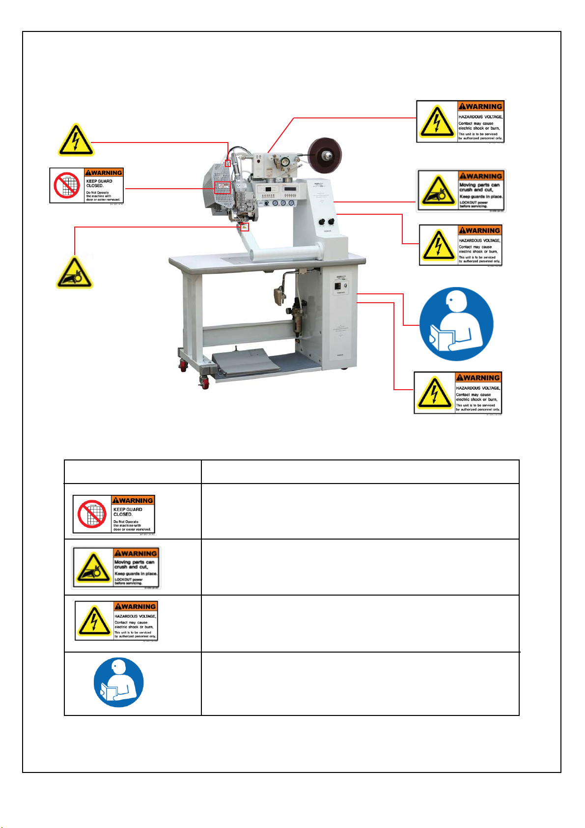
□ All transport, installation, operation, and maintenance related safety
information should be well noticed before using the machine.
□ An exporter should control all processes from transport to installation
which have a direct influence on the safety of machine and operator.
□ When the equipment is transported by a forklift, an operator should
watch out several power cords on the floor. Besides, an operator should
be careful not to have the machine dropped on the floor.
□ Operators should be correctly informed of this manual (operation,
application, and management) and watch out all possible occupational
hazard and risk factors.
□ If necessary, safety equipment can be installed for operators’ safety.
A supervisor should carefully examine the equipment and machine to
prevent any accident caused by outdated machine.
□ With proper lubrication and electric facilities, endurance of the machine
should be improved and any possible accident should be prevented.
□ A supervisor should always be dutiful in enhancing endurance of
equipment and preventing occupational accident.
Y

□ All machine facility and parts in use should be included in "PART LIST."
□ Proper support equipment and consumable goods are always reserved.
□ When heavy parts are transported by a crane or forklift, safety check must be
done in advance. Whether or not the parts are too heavy to transport should be
checked and an operator watch out any worker under the cargo.
□ While transporting the machine in accordance with the instruction of the manual,
the evenness of the floor and hardness of the material should be checked in
advance to prevent any accident.
□ For fire safety, automatic sprinkler systems, automatic extinguisher,
or hydrant should be installed around equipment.
Z

OYPGsGGkGGzG~Gz
XUGzhml{G~hyupunGzpnuz
zG~Gz k
yGGGGGGGG
~GGGGG
~GGG
iGGGGGGG
[

(3) Periodical Check
Users should check maintenance & repair checklist in accordance with
maintenance manual. (Daily, weekly, monthly)
Period No Description CHECKING
DAILY
WEEKLY
MONTHLY
1
2
3
1
2
1
2
3
4
5
Remove moisture in air filter
Remove moisture in compressor
Clean and check nozzle
Regular check on electric parts
Foot switch check
Lubricant check
Clean air filter
Bolt (Knife) check
Shaft bolt check
Chain tension part check
5

(4) Purpose of Machine and Installation
1) Most waterproof textiles are made of performance fabric which passes through
air but blocks water. However, water may pass through needle holes which are
created during sewing as shown in <Figure B> below.
[Figure A] [Figure B]
[Figure C]
Properly Sealed No Air Allowed
6
2) In order to prevent water leak through the seam, this machine seals the seam
using hot wind as shown in <Figure A> above.
3) If the seam is properly sealed, there should be no air on the tape sealing space
as shown in <Figure C> below. Air could be created due to machine speed,
temperature, or pressure. The fabric and tape should be checked as well.

4) Installation
- Place machine keeping 50cm distance from walls and lock the wheels with locking
lever on the left wheel.
5) Air and Power Connection
ⓐ Air pressure: 5kg/cm2 - 6kg/cm2 / Compressor capacity for 1 set: 3HP
(NOTICE) Under low pressure, warning alarm may not go off and machine
won’t be operated.
ⓑ Power Connection
Power is connected by 1P 220V.
For both 50Hz and 60Hz
If the voltage is lower than 210V
or higher than 240V,
stop the operation.
7

(5) Preliminary Check before Operation
1) Check if air filter gauge pressure exceeds 5kg/cm2 (FT1 in Figure 1 below)
Adjust the pressure to over 5kg/cm2 with adjusting lever
If lower than 4kg/cm2, warning alert goes off and machine stops.
2) Check filter air tank and remove moisture if any
. (FT2 in Figure 1)
3) Check if nozzle air pressure exceeds 1kg/cm2.
If it doesn’t, do the adjustment (RG 1)
If the pressure is lower than 0.8kg/cm2,
nozzle temperature doesn’t go up any more.
4) Set the tape.
(See Tape Setting in page 14)
5) Switch on the power.
(Power SW1)
6) Switch on the nozzle temperature.
(See Temperature Input Method in page 25)
7) Switch on upper roller heater.
(See Temperature Input Method in page 25)
For temperature rise in upper roller,
it takes about 10 minutes.
8) Set proper speed
Type of TapeSpeedTemperature* Adjust the speed depending on the type of tape and fabric.
* Under over 4m/min, 3-layer tape becomes the cause of water penetration
9) Relation between speed and temperatur
mGX
m{Y
ynY
ynX
ynX
ynY
m{X
wv~lyGzV~
{GG z {
YG
ZG
\¥^V
Z¥[V
[WW¥\WWሚj
\WW¥]WWሚj
_
* Adjust the speed depending on the type
of tape and fabric.
* Under over 4m/min, 3-layer tape
becomes the cause of water penetration
1) In order to get high-quality products, the selection of type and width
of nozzle is important (See Type of Nozzle in page 13)
2) For this machine, compressor capacity should be 3HP and 1KW
of electricity (220V) is needed.(compressor capacity excluded)
m{Z

(6) Pedal S/W Operation
ⓐ UP / DOWN of Upper Roller (S/W “B”)
1) Whenever Pedal S/W B in [Figure 1] is stepped on, the upper roller moves
up and down.
S/W “B” (Upper rollr part)
[Figure 1]
ⓑ Start Operation (S/W “A”)
1) If Pedal S/W A in [Figure 1] is slightly stepped on,
roller revolves and a nozzle moves.
2) If it’s hit on hard, the tape is cut off and a nozzle stays in a roller for some time
and returns to an original place. Then, the upper roller goes up after revolving
for some time. Then, tape keeps going down up to the next work position.
S/W “A” (Nozzle part)
ⓒ Finishing Up (Switch Off)
1) Switch off nozzle temperature and roller temperature
2) If the nozzle temperature is lower than 70℃, remove air. Switch off power.
3) If air is removed before nozzle temperature falls, a heater may break down.
9

(7) Adjusting UP / DOWN Speed of Upper Roller
Before adjusting the speed,
① check if air supply pressure in foot board filter exceeds 5kg/cm2. If it doesn’t,
the adjusting job may not be done properly. (Gauge pressure of FT1 in Figure 3)
② fully turn pressure adjusting lever in upper roller pressure press (RG2 in Figure 3)
to the right. After checking the description above, slowly turn J1 and J2 in [Figure 1]
and set proper speed (to the level that no tremble is detected in machine).
J1 is adjusted during UP while J2 is adjusted during DOWN.
A
J1
J2
H1
H2
[Figure 1]
[Figure 2]
(8) Nozzle Speed Control
Adjust the speed by turning H2 and H1 in [Figure 1] above. H1 adjusts the speed
when a nozzle moves toward roller while H2 adjusts the speed when a nozzles moves
from roller to the outsides.
If a nozzle moves too fast, a heater could break down.
* Speed Adjusting Lever
After adjusting the speed by turning A2 bolt in [Figure 2],
A2 movement should be prevented by A1 nut.
A2
A1
10
mGZ
m{Y
ynY
ynX
ynX
ynY
m{X
wv~lyGzV~
m{Z

(9) Upper Roller Stroke Control (Figure 5)
Stroke needs to be adjusted depending on type of fabric and tape.
* In an adjustment of stroke, the upper roller should face upward for easy adjustment.
① In case of thin fabric or tape, be careful not to damage the tape.
② In case of thick fabric or tape, it should be adjusted
until a roller is slightly crushed for water penetration effect.
③ If a roller is crushed too much, it could be easily damaged. Therefore, it should be
adjusted enough for the fabric not to be slipped out even if it’s strongly pulled out.
At the same time, the upper roller pressure should be adjusted. (3~5kg/cm2)
(10) Upper Roller Pressure Control
For the upper roller pressure, there are upper roller pressure gauge on the panel
and adjusting regulator.
Adjust the pressure by turning RG1 in Figure 4 and checking RG2 gauge.
Normal 2 Layer – 3kg/cm2
3 Layer – 4kg/cm2 ~ 5kg/cm2
[Figure 4] [Figure 5]
Strock control Lever
11
m{Y
ynY
ynX
ynX
ynY
m{X
wv~lyGzV~
m{Z

(11) Nozzle Position Control
Notices before adjusting nozzle
- Make sure that temperature is low.
- Make sure that power and air are off.
- After manually adjusting nozzle, do the
precise adjustment with power and air on.
Bolt H
Front/Back adjust
bolt “C”
Up/down adjust
Lever B
Up/down adjust
Bolt A
Guage I
Left/Right adjust
Bolt E
5mm from Center
left/right
[Figure 1]
1) Open the Nozzle Cover - If the Bolt “H” is released in [Figure 1], The cover will be opened
2) Adjust the Nozzle (Up/Down) [Figure 2]
1. After slightly Loosening the Bolt “A”,
2. Looking the Guage of “I”
3. Adjust proper distance by turning nut lever “B”
4. After the adjustment, lock bolt “A
Front/Back adjust
Lever D
Guage “J”
Left/Right adjust
Bolt “E”
up/down
[Figure 2]
[Figure 3]
Front/Back
2~3mm
[Figure 4]
[Figure 5]
2) Adjust the Nozzle
(Front/Back) [Figure 5]
1. After slightly Loosening
the Bolt “C”,
2. Looking the Guage of “J”
3. Adjust proper distance
by turning nut lever “D”
4. After the adjustment,
lock bolt “C
4) Adjust the Nozzle of Left/Right
1.
Adjust the
Left/Right
by turning nut lever “E”
.
2.
After the adjustment, by Nut
12
[Figure 6]

(12) Nozzle Angle Control (Figure 6)
In order to adjust nozzle angle, make sure that the temperature is low.
In case fabric is severely crushed (2-layer) or burnt (3-layer) when sealed with
seam sealing tape, the nozzle angle should be adjusted.
1) Once the heat cools off, slightly loosen bolt F and tightly fasten bolt with
(+) screw driver holding nozzle with spanner.
2) After nozzle is heated, bolt F can be loosened. Then, nozzle angle can change.
Then, screw bolt F again holding the nozzle with spanner (Keep watching out HEAT)
[Figure 6] [Figure 7] [Figure 8]
* Nozzle Cleaning
If nut G is turned to the left once a nozzle is cooled off, the nozzle is separated
from heater housing. Mildly stir nozzle upside down and remove foreign substance
(glass powder) in a nozzle. If nozzle is blocked, the sealing would not be properly done.
Then, a heater problem may be followed.
If nut G in Figure 7 is turned while a nozzle is heated, G thread could be spoiled.
(13) Type of Nozzle (Figure 8)
As shown in Figure 8, a type of nozzle is as follows:
2 Layer – PU, PVC tape used
3 Layer – In order to prevent fabric burning, it’s designed for heat to be dispersed.
Used in 3-layer fabric
Width of nozzle: A nozzle should be 1-2mm wider than tape.
13
Bolt F
Up roller
Down roller
Nut G
2-LAYER 3-LAYER

(14) Tape Setting
ٺ
mGX mGY mGZ
1) Install the tape in order as shown in [figure 1] ※ Watch out nozzle heat!
2) You can feed the tapes by using the Feed lever as Shown [Figure 2]
3) As [Figure 3], by using “tape width adjusting lever”, adjust the guide.
** Set the tape as shown in figure..
X[
- NOTICE -
1) Make sure that tape surface faces front.
2) If tape guide is too narrowed, puckering may occur.
If it’s too wide, it could be folded at pause and
the tape would come and go (tremble) in roller.
3) The tape feederspeed (VR1) should be adjusted
a little faster than machine speed.
{hwlGn|pkl
wv~lyGz~
QG{G~GhGsGQ
iGG|wVkv~uSGG
GUGpGGGG
GGU
hpyGhkq|z{punG}hs}l

(15) Nozzle Heater Air Control
Adjust the air by turning RG1 to the right or left and checking RG 1 gauge.
Normally, 2 LAYER (PU, PVC) 1~1.2kg/cm2 / 3 LAYER 1.2~1.8kg/cm2
- NOTICE: If air gauge is below 0.8kg/cm2, temperature does not go up.
mG\ X
Y
Z
[
\]^
`
_
ivs{Gˈhˉ
(16) Nozzle Heater Replacement
Nozzle heater should be replaced when power is switched off.
Remove 1 in Figure 5 by turning it to the left.
Remove two bolt 2 in Figure 5 by turning it to the left and replace nozzle heater 9.
Power switched off – See Figure 6, 7, and 8
Replace nozzle heater sensor – Sensor error is displayed on LCD.
** If the temperature blinks for over 20 minutes, check heater sensor
Replacement of roller heater – Temperature blinks on the LCD
Replacement of roller sensor heater – Temperature blinks on the LCD
X\
mG] mG^ mG_
m{Y
ynY
ynX
ynX
ynY
m{X
wv~lyGzV~
m{Z
[Figure 4]

(17) Replacement of Upper Roller Heater and Upper Rubber Roller
1) Replacement of Roller Heater
Loosen bolt A and remove if from upper roller.
Then, loosen and replace bolt B and C.
mGX mGY
mGZ
2) Replacement of Upper Roller
Loosen bolt A in [Figure 2], remove
B plate, and then replace the roller.
3) Replacement of Lower Roller
Loosen bolt A, B, and C in [Figure 3],
remove D plate, and then replace
the roller.
h
h
h
i
i
i
j
j
X]
k

(18) Problem Check
▶ Replacement of Rubber Roller (Upper / Lower Roller)
In case one of the following problems is detected, replace the roller.
NOTICE:
ⓐ Because rubber roller spins under burning heat, it should be replaced
with NAWON roller (there could be a problem in sealing)
ⓑ A roller should be replaced while the temperature is off.
① A stain is observed on a tape after seam sealing.
② Even though tape guide is adjusted to the wide of tape,
tape moves to the right and left in a roller.
③ Because the corner of roller is worn out, a roller has become soft.
Bad sealing on the left and right
④ A rubber and steel core in a roller are separated.
▶ Replacement of Foot SW
① Even if foot board is stepped on, PCB (CN6) LED (D11, D12, and D13)
does not turn on.
② Check the power cord to the terminal
▶ Replacement of Heater
First, check the followings:
① Check if the heater pressure exceeds 0.8kg/cm2.
If it doesn’t, do the adjustment with heater air.
② Check if SENSOR ERROR (b.out) is displayed on temperature LCD.
(If SENSOR properly operates)
③ Check if temperature LCD is properly displayed
(process value and present temperature)
④ Switch off heater cable and connector check power and remove cable terminal.
If heater is checked as "Ω" by a tester, it’s normal (about 16Ω)
⑤ Nozzle temperature SW check
Check if the connection is okay when switch turns on and off.
Check the connection by "Ω" at No. 23 and 24 of Terminal T1.
Check under switch ON and OFF
If no problem is detected after checking the 5 items above, replace the heater.
X^

▶ Replacement of Thermometer (p 28, K401 T08, K402 T08-2)
① Temperature goes up and down greatly.
(It could happen after data input is adjusted)
☞ Contact「NAWON」
② The numbers on LCD change quickly.
③ Temperature doesn’t go up even though no problem is observed
in nozzle heater sensor and heater.
④ Thermometer LCD doesn’t turn on.
⑤ Check if thermometer’s switch operation terminal (T1) No. 23
and 24 are properly connected by a tester.
▶ A heater keeps breaking down.
① Replace TPR 501 unit with new one
② Clean nozzle (see page 13 and 21)
Nozzle wind from the left and right is not stable.
Check if the nozzle wind is okay.
③ If work area is humid, the moisture in filter and compressor should often
be removed.
☆ Air dryer needs to be installed
④ Check if pressure safety SW (PS220) properly operates
If nozzle pressure is less than 0.8kg/cm2, check there is any noise
in a machine room.
⑤ Check heater cable and connection
▶ Replacement of Solenoid
① Knife, upper roller, nozzle, and tape feed do not move.
② Check PCB (CN6) LED (D2. V. ROLLER / D5. NOZZLE / D6. T-FEED
/ D16. KNIFE) is properly displayed.
Check LED turns on when foot board is stepped on.
③ Check if voltage is confirmed in PCB connector (CN1, CN5)
No. (S01 V. ROLLER / S02 NOZZLE / S03 T-FEED / S04 KNIFE)
by a tester (220V).
X_

▶ Circuit Problem (p28, K404 W06-2)
Check the followings:
① Check power 12V (W46-12) input voltage (Normal if "OK")
② Check input and output LED display when foot board is stepped on
(Normal if "OK", bad circuit if "NO")
▶ A roller doesn’t spin.
(a) Both upper roller and lower roller do not spin.
① Check motor
② If motor driver (M201) LED (green) is on, a driver (M201) is normal
If it blinks, there is a problem in either driver (M201) or motor
Before replacement, try to switch on and off main power.
If it keeps blinking, there is a problem in either driver (M201) or motor.
③ If a motor driver (M201) LED (green) is off, bad motor power 24V (M201-24)
(b) Both upper and lower rollers spin one direction only.
① Check powertransmission chain (see Power Transmission in page 29)
▶ A nozzle does not move
① Check thermometer error message on LCD.
Bad thermometer and temperature
② Check solenoid circuit
Check if D5. NOZZLE LED and CN1 connector S02 (220V) properly operate
▶ Error Messages
▷ Air Low
Weak main air pressure (filter gauge in foot board) → Increase to over 4kg/cm2
※ Nothing moves
If PCB LED D3 OFF, the pressure is less than 4kg/cm2 or check pressure (PS220) SW
▷ Temperature error (only if upper roller heater is installed, OPTION SPEC)
Thermometer and temperature error
※ A nozzle does not move.
▷ Roller set temperature blinks (only if upper roller heater is installed, OPTION SPEC)
Roller temperature error
Roller temperature normally operates in 10 minutes from SW ON
Under normal operation, roller set temperature does not blink.
X`
Table of contents