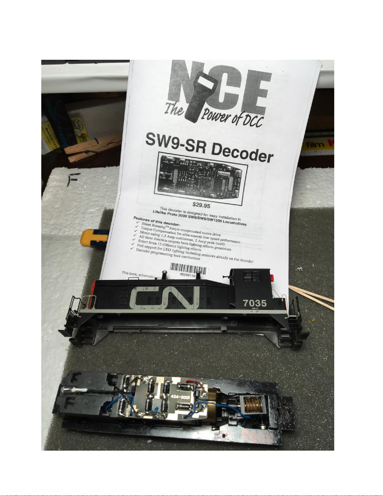
Install an NCE SW9-SR mobile Decoder into an P2K SW1500 switcher.
CN 7035 EMD SW1500 Switcher:
The PROTO 2000 SW1500 switcher by Walters, formerly LifeLike, is a very versatile and smooth running
locomotive, even in DC mode. DCC really makes it shine. The limited space under the shell makes it very
challenging to add a DCC Decoder. NCE makes a mobile Decoder (non sound) specifically designed to fit
in this switcher’s shell.
It might be possible to put a mini speaker in the cab, but it would still be a challenge to put a sound
decoder and keep alive capacitor in the shell. However, it is worth noting that the manufacturer of this
locomotive (LifeLike) did have the forethought to make a removable section of the lead weight at the
front to allow space for a small decoder. This section attaches to the main body of the weights by two
screws. If attempting a sound decoder installation, and you are using the optional space provided by
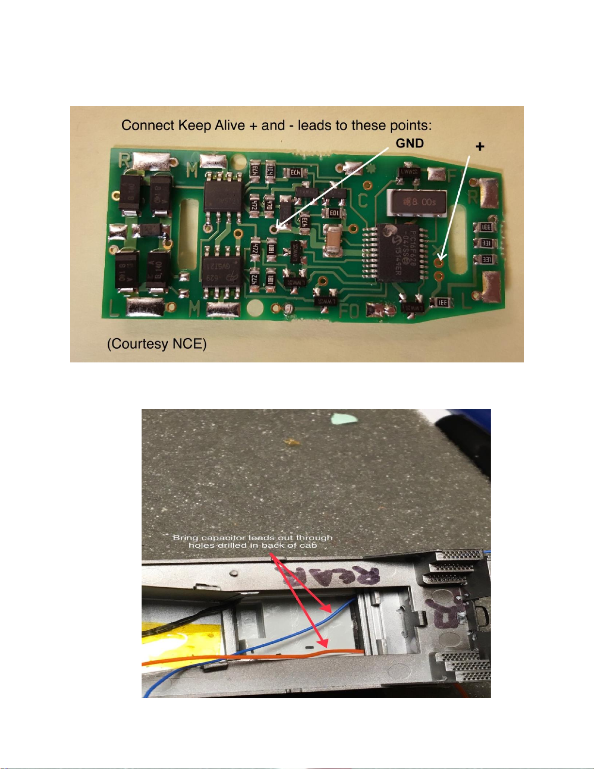
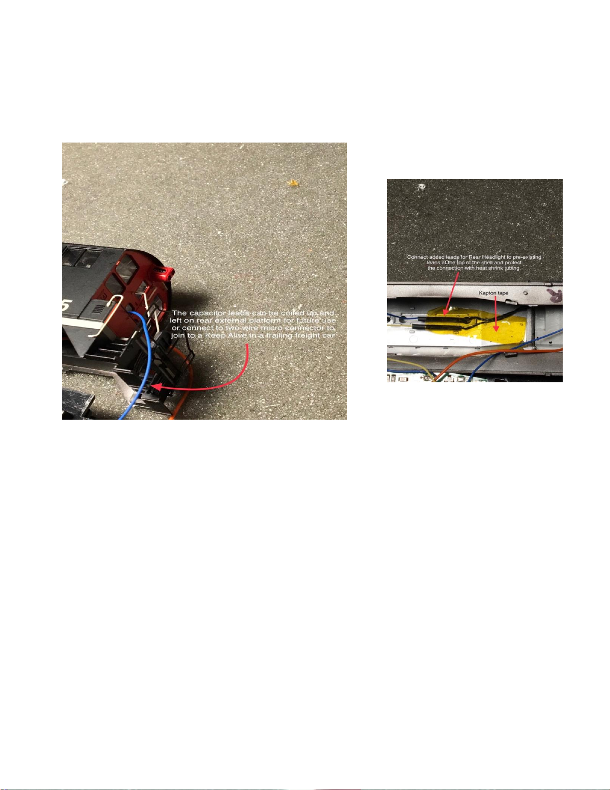
removing a section of the front weight for the Sound decoder, and a keep alive current capacitor is
deemed necessary, it could be placed in a freight car behind the switcher, and connected with a 2-wire
micro-connector. This freight car would then be tethered to this switcher whenever using the keep alive.
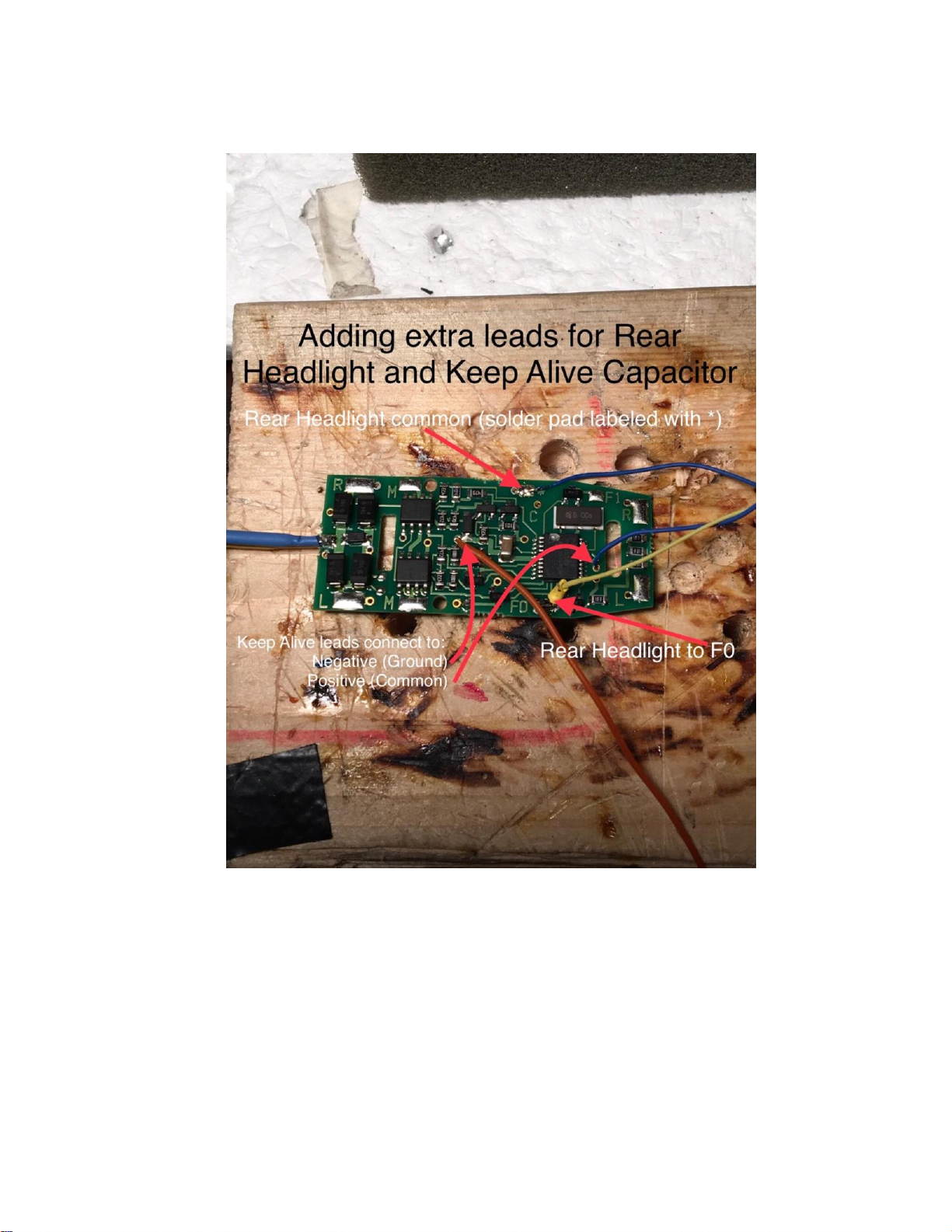
Another option, should a keep alive be deemed necessary, and you are just installing the NCE mobile
Decoder (non sound), is to place the keep alive capacitor in the space provided by removing this front
section of the lead weight.