NCE Switch-It Mk2 User manual

Switch-It Mk2
Version 1.0
FOR STALL MOTOR MACHINES ONLY
NOT FOR USE WITH TWIN COIL SWITCH MACHINES
$29.95
All new easy programming!
‚
‚‚
‚Control for 2 Tortoise
TM
switch machines
‚
‚‚
‚Remembers the position of switch during power outages
‚
‚‚
‚Supports the full range of DCC accessory addresses (1-2044)
‚
‚‚
‚Easy address programming, no need to connect it to programming track
‚
‚‚
‚Push button connections for local control panel operation
‚
‚‚
‚Simple hook up, 2 wires to the track, 2 wires to each switch machine
Age
14+
Warning: This product contains chemicals known to the state of California to cause
cancer, birth defects or other reproductive harm.
05240154
05240154

Notes:
This decoder is designed to control Tortoise, SwitchMaster or other low current "stall
motor" switch machines. The outputs are rated for 40mA maximum. Most Tortoise
machines draw 10 to 20mA with normal track voltage (about 13-15 volts). There are
four mounting holes at the corners of the Switch-It.
Wiring:
See the diagram below for wiring particulars. The only required wires are two wires to
the track and two wires to each machine. It is OK to use the Switch-It for control of only
one switch machine.
Caution when using local control pushbuttons. The “C” in the drawing above used
as a common for pushbuttons is circuit common for the Switch-It. Do not connect to
other Switch-It common terminals unless the other Switch-Its are connect to the same
power district.
Switch machine mounting tip:
On our Tortoise machines we use hot glue to mount the machine. The glue stays
liquid just long enough after application to allow alignment of the machine. We
manually center the arm of the machine then slide the machine around while the glue
sets to align the points to the middle of their throw. The low temperature hot glue is
weak enough to allow removal of the machine later on by prying with a putty knife. Use
a throw wire that is about 6” (150mm) longer than the one provided with the Tortoise to
give you room to put glue on the machine after the wire is put through the roadbed
.
Last revised: 16 September 2014 Copyright 2014 NCE Corp Page2
To Track
SWITCH
MACHINE
"A"
SWITCH
MACHINE
"B"
Tortoise Machines
Illustrated above
SWITCH-IT wiring diagram
"Local" control push buttons
can be mounted on fascia,
control or dispatcher panels
OPTIONAL
4
3
2
1
SwitchIt-Mk2 Rev A
ADDRESS
DISPLAY
TRK 1N 1R 2N 2RCC
PROGRAM
OUTPUT
SELECT OUTPUT
A B
1A B
2
OUTPUT LEDS

If you have never used a Switch-It-MK2 before:
We recommend trying the decoder out first before installing it on the layout.
Connect a Tortoise
TM
machine to screw terminals 1A/1B of the decoder
Connect two wires from the decoder track connection to your DCC system.
When you first apply power to the Switch-It-MK2 the address display will show some
numbers (the software version) then 3 horizontal bars for about 1 second followed by
vertical bars”wig wagging” back and forth on the display. The wig-wagging indicates
the decoder is receiving DCC information and is ready for use.
Press the “SELECT OUTPUT” button the decoder until the output LED above the
1A/1B terminal strip lights (each push of the button will select a different output - on the
ninth push all LEDs will turn off). The address display will now start indicating the
output currently programmed for that output. For a factory fresh Switch-It-MK2 output
#1 it will flash 1. If you select output 2 it will flash 2 and so on as indicated below:
Factory default values for decoder
Output 1 factory programmed to accessory address 1
Output 2 factory programmed to accessory address 2
Now let’s actually test the decoder output #1.
Use your DCC system to throw the switch. The instructions below can be used for
throwing a switch depending on which DCC system you have:
To throw a switch using the NCE system:
Press “SEL ACCY”
Type in the desired accessory number followed by “ENTER”
Push “1” (or “2”) to throw the switch.
To throw a switch using a Digitrax system:
Press “SWCH”
Type in the desired accessory number
Push “OPTN” to throw the switch.
To throw a switch using a Lenz system:
Press “F”
Press “5”
Type in the desired accessory number followed by “ENTER”
Push “+” (or “-”)
If throwing the switch one way doesn’t do anything, try the other direction. You should
be rewarded with the Tortoise reversing its position.
Last revised: 16 September 2014 Copyright 2014 NCE Corp Page3

Address programming:
The Switch-It cannot be programmed on your programming track. It is always
programmed while connected to the mainline track. This decoder can be programmed
by all systems that support accessory control using the procedure below.
To program an output to a new address using any DCC system:
1) Connect wires from the track to the decoder DCC terminals.
2) Make sure the Power Select Switch is set to DCC.
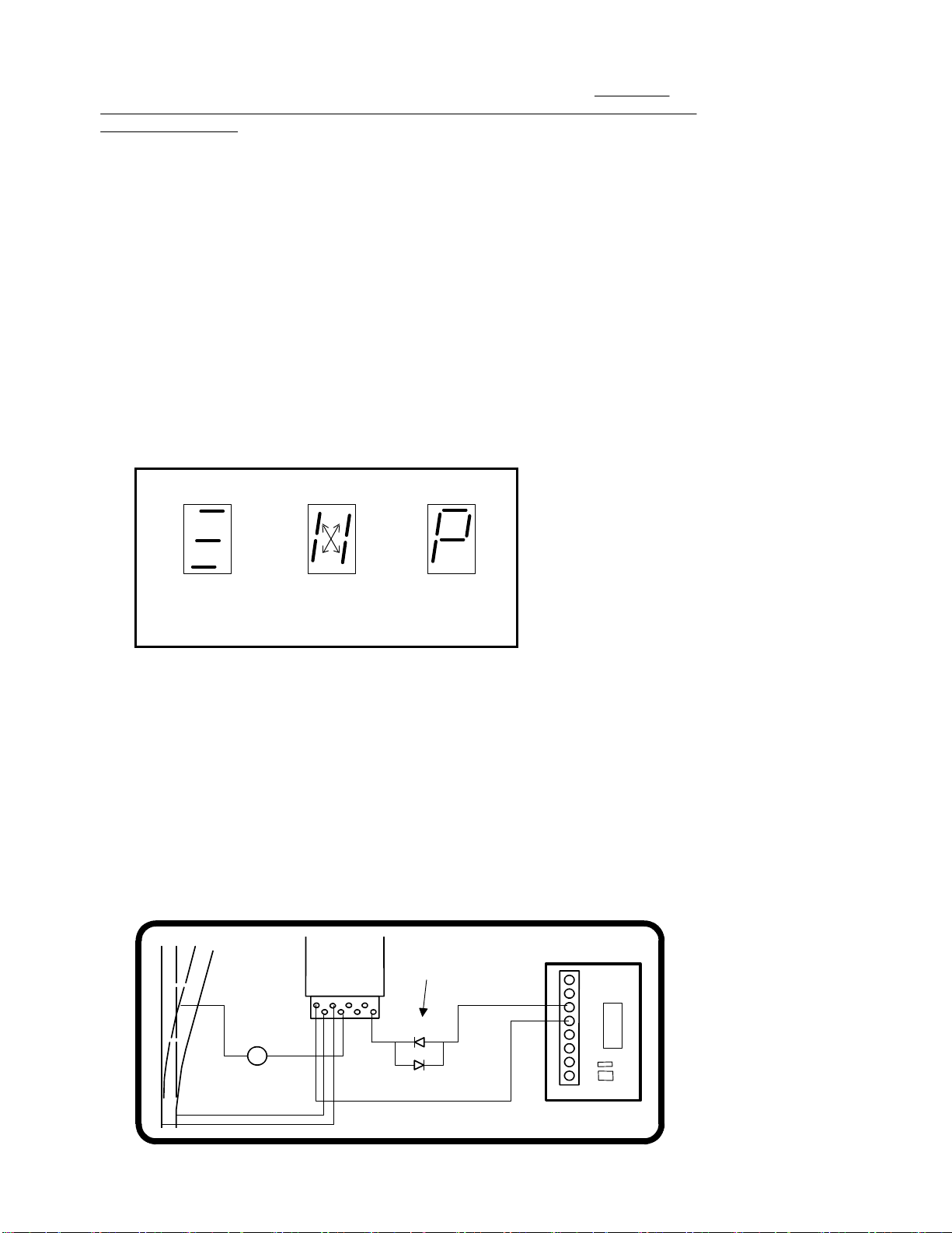
3) Push the SELECT OUTPUT button until the LED corresponding to the output
lights.
4) Push the PROGRAM OUTPUT button (notice the display flashes “P" now) When
the display is flashing you have one minute to complete the next step or the
decoder will exit programming mode.
5)
Use your DCC system to select and operate the switch (see above).
6)
The decoder will accept that switch address as its new address and begin
showing its new address on the address display. It will show the address one
digit at a time in sequence.
You may confirm the address for any output at any time by pressing the OUTPUT
SELECT button until the appropriate output LED lights. The address for that output will be
displayed.
Setting other options in the Switch-It-Mk2:
Use Accessory OPs mode programming (“PROG” followed by “7” on NCE systems).
If you have an entry level system that does not support Accessory OPs mode
programming follow the instructions on the back page for setting CVs with Loco Ops.
For CV561 through CV568 use the accessory address for the corresponding output
number. For all other CVs use the accessory address programmed for output 1.
Reversing the polarity of an output:
Each of the outputs can have its polarity reversed by programming a CV for that output.
The programming commands for changing the polarity must be directed to Accessory
address of the respective output number. For example, if output 1 is programmed to
Accessory address 226 then you need to select Ops mode programming for address
226, and then set V561 accordingly
For output #1 program CV561 to a value of 0 (default) for normal polarity, 1 for reverse.
For output #2 program CV562 to a value of 0 (default) for normal polarity, 1 for reverse.
If your DCC system does not support OPs mode programming for accessories you can
just swap the two wires to the switch machine.
Setting outputs to toggle when used with optional local control push buttons
Setting CV548 to 1 will cause pushbuttons connected to the Switch-It to “toggle” the
switch machine output. Each press of a button will alternate the switch position.
Setting CV548 = 1 enables the toggle option. CV548 = 0 disables it.
CV548 is “global” to the Switch-It Mk2, meaning it will affect all buttons connected to
the Swtich-It . (Factory default = 0) Note: V548 should be programmed via
Accessory Ops mode programming to the address of output 1 only.
Pushbutton Lockout (CV556):
On some layouts it may be desirable to disable operation of the local control
pushbuttons. Setting CV556 to a value of 1 prevents operation of all the decoder
outputs by the optional Button Board pushbuttons. Setting CV556 to 0 enables
operation of these buttons. You can disable or enable ALL decoders on the layout at
the same time by using the accessory decoder broadcast address of 2044 when
programming CV556. CV556 is “global” to the Switch-It Mk2, meaning it will lockout all
button inputs from the button board. (Factory default = 0) Note: V556 should be
programmed via Accessory Ops mode programming to the address of output 1 only.
Last revised: 16 September 2014 Copyright 2014 NCE Corp Page4

Factory reset:
To reset the Switch-It-MK2 to original factory setting program CV8 to 8. A reset will
only be performed if you program CV8=8 via Accessory OPs mode programming to the
address of output 1.
Upon reset all settings will revert to the factory default setting as indicated below.
Factory default values for decoder
The Switch-It-MK2 is factory programmed to the following values
Output 1 = accessory address 1
Output 2 = accessory address 2
CV548 is set to 0 (normal dual pushbutton operation by the optional Button Board)
CV556 is set to 0 (pushbutton lockout not engaged)
CV561 is set to 0 (normal output polarity)
CV562 is set to 0 (normal output polarity)
Other technical stuff:
vWe have successfully controlled two Tortoise switch machines with one decoder
output when used in a crossover. We can't guarantee this will work in all cases.
vThe outputs of the decoder are always on to prevent the switch machine from backing
off due to the spring pressure of the turnout throw mechanism.
Indications shown on Address Display
Decoder has
power but is
not receiving
DCC information
"Wig-Wag"
receiving
DCC info and
is operational
Flashing "P"
decoder is
ready to accept
new address
More wiring tips:
If you use the Tortoise contacts to power the frog of your turnouts we suggest
wiring a #93 (other useful bulbs #211, #305) automotive bulb in series with the frog
(see below). This will prevent short circuits from shutting down your power booster
in the event you enter the turnout from the frog end without aligning the points. For
larger scales use a #1156 bulb.
See the diagram below for and easy way to have turnout position indicator lights.
LEDs are wired in series with the switch machine to indicate which position the
turnout is thrown. Most LEDs will handle up to 20mA, the switch motor acts as the
current limiting device for the LEDs. We use red and green LEDs but any color will
do. The switch machine will run a bit slower with LEDs installed due to about a 1.5
volt loss in the LEDs .
RED
GREEN
#93
Bulb
LEDs
Tortoise
Machine
Shown
Last revised: 16 September 2014 Copyright 2014 NCE Corp Page5

You can connecti normally open (N.O.) pushbuttons or toggle switches to the
Switch-It-Mk2 for control of turnouts via a control panel near the Switch-It-Mk2. Toggle
switches can be momentary or non-momentary.
Grounding terminal 1N of the button board will activate output 1 of the Switch-It to the
“normal” position. Grounding 1R will throw the Switch-It to the “reverse” position.
Programming CVs with systems that don’t support Accessory OPs mode
programming:
Press the SELECT OUTPUT button on the Switch-It-Mk2 until the button for output #1
lights.
Press PROGRAM OUTPUT (the display should start flashing “P”)
Use loco OPs mode programming (Program on the Main) to program the desired CV.
Any loco address can be used for this.
Repeat the steps above for each CV you wish to program.
If the programming “takes” the display will stop flashing.
Note:
The display will only flash for about 1 minute. When it stops flashing the Switch8-Mk2 will
not accept programming. If it times out and stop flashing before you finish programming
just press PROGRAM OUTPUT again.
Note:
You can only program CVs using Loco OPs mode when output #1 is selected. If any other
output is selected Loco OPs will not work (only Accessory OPs works with all outputs)
The warranty is voided if the decoder is miswired, connected to more than 22 volts, or used with switch motors
drawing more than 40mA.
Warranty
This decoder is fully factory tested and warranted against manufacturing defects for a period of 1 year. As the
circumstances under which this decoder is installed can not be controlled, failure of the decoder due to
installation problems can not be warranted. This includes misuse, miswiring, operation under loads beyond the
design range of the decoder or short circuits. If the decoder fails for non-warranted reasons NCE will replace
the decoder, no questions asked, for $20 US plus $2 shipping. For warranty or non-warranty replacement send
the decoder (an any payment, if required) to:
NCE Warranty Center, 82 East Main Street, Webster, New York 14580
The terms Power Pro, ProCab, Power Cab, the NCE logo with “Power of DCC” slogan and the distinctive shape of the
ProCab with thumbwheel and LCD are trademarks of NCE Corporation. Digitrax is a trademark of Digitrax Inc.
Last revised: 16 September 2014 Copyright 2014 NCE Corp Page6
05240154
05240154
Table of contents
Other NCE Media Converter manuals