NCT M&H IRP40.02 User manual

M&H IRP40.02
INFRARED TOUCH PROBE
OPERATING INSTRUCTIONS
NCT Ipari Elektronikai Zrt. 1 / 25 23 May 2023
H-1148 Budapest, Fogarasi út 7.
Phone: +36 1 467 6300
www.nct.hu
M&H IRP40.02
INFRARED TOUCH PROBE
OPERATING INSTRUCTIONS

M&H IRP40.02
INFRARED TOUCH PROBE
OPERATING INSTRUCTIONS
NCT Ipari Elektronikai Zrt. 2 / 25 23 May 2023
H-1148 Budapest, Fogarasi út 7.
Phone: +36 1 467 6300
www.nct.hu
TABLE OF CONTENTS
1DESCRIPTION ................................................................................................................3
1.1 General.........................................................................................................................3
1.1.1 Preface..................................................................................................................3
1.1.2 Safety Instructions................................................................................................3
1.1.3 Declaration of Conformity ...................................................................................4
1.1.4 Validity.................................................................................................................4
1.2 Purpose ........................................................................................................................4
1.3 System Components ....................................................................................................4
1.4 Technical Data.............................................................................................................5
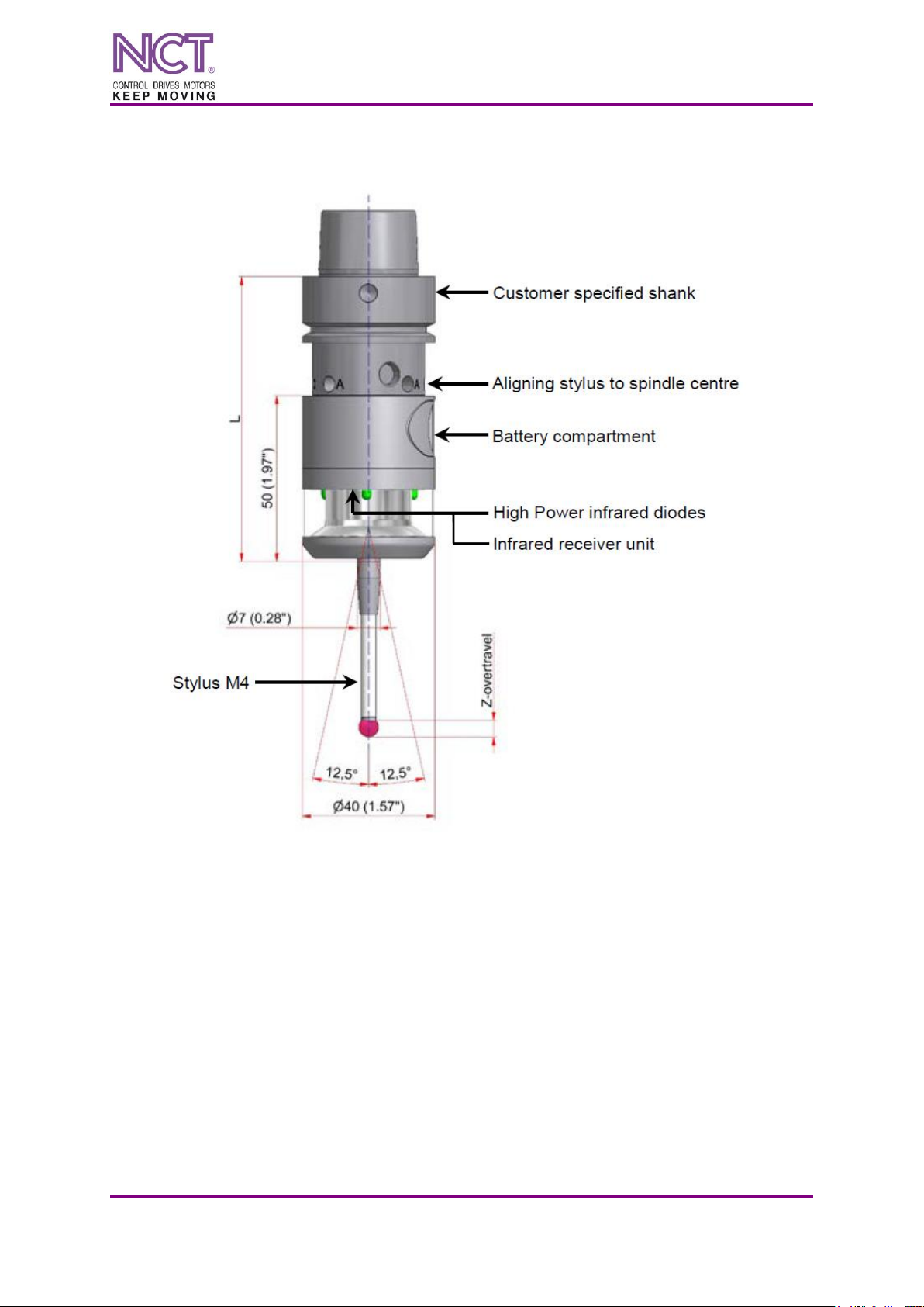
1.5 Dimensions..................................................................................................................6
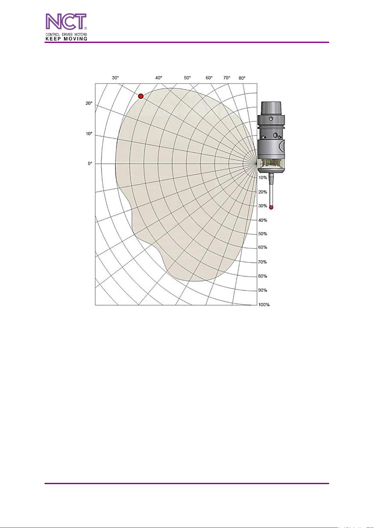
1.6 Transmission-/Reception Angles.................................................................................7
1.6.1 Transmission Angles............................................................................................7
1.6.2 Reception Angles .................................................................................................8
1.7 Delivery Contents, Accessories and Spares ................................................................9
1.7.1 Delivery Contents.................................................................................................9
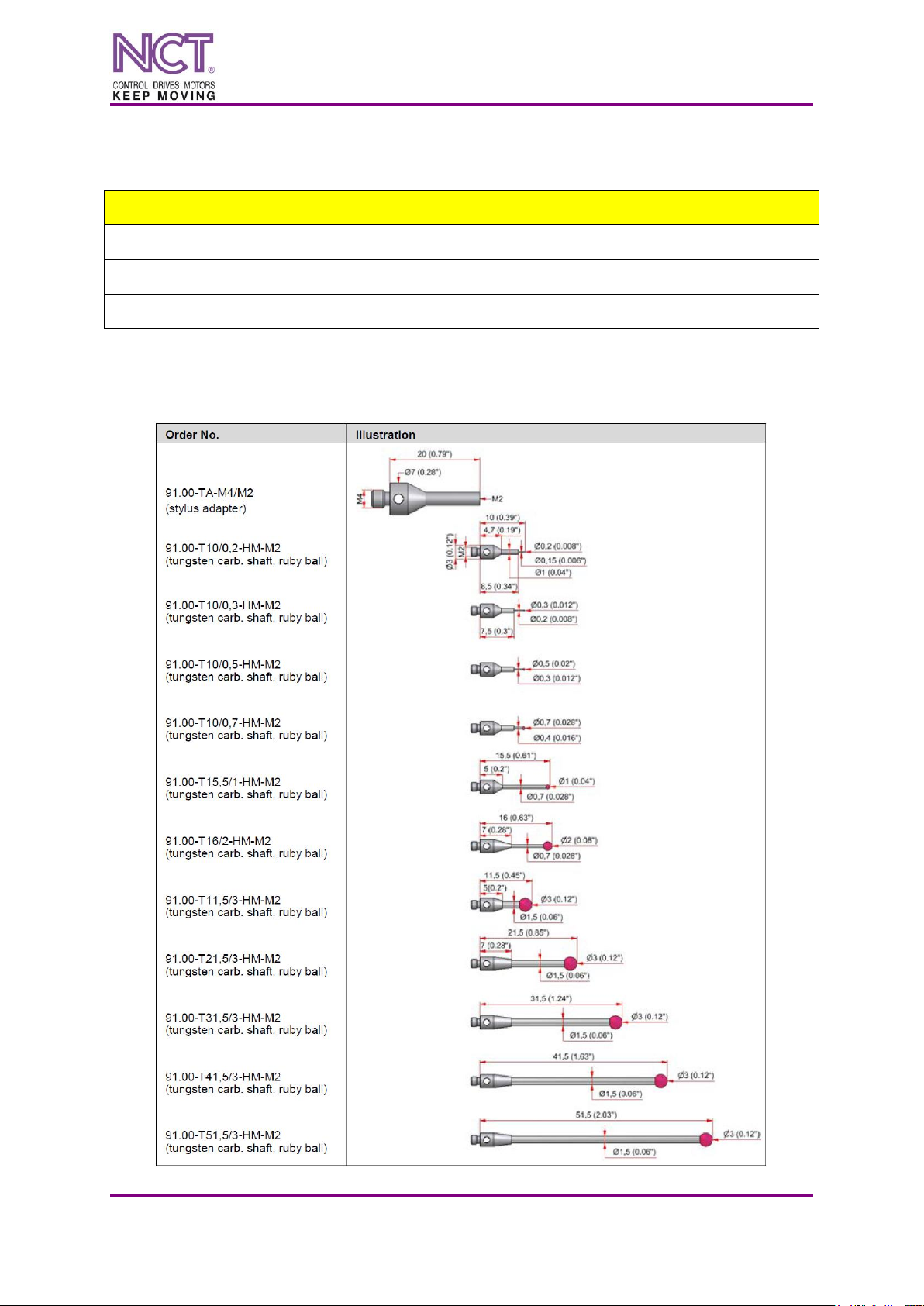
1.7.2 Styli ......................................................................................................................9
1.7.3 Shanks ................................................................................................................12
1.7.4 Accessories, general...........................................................................................17
1.7.5 Spare Parts..........................................................................................................17
2OPERATION..................................................................................................................18
2.1 Tools, Measurement- and Test-Equipment ...............................................................18
2.2 Changing Stylus.........................................................................................................18
2.3 Mounting/Dismounting the Shank.............................................................................19
2.3.1 Mounting shanks 20........................................................................................19
2.3.2 Mounting shanks 28........................................................................................20
2.4 Replacing Battery ......................................................................................................21
2.5 Aligning Stylus to Spindle Centre.............................................................................22
2.6 Aligning Probe in Shank with 90° Adapter...............................................................23
2.7 Optical Status Display ...............................................................................................23
2.8 Maintenance and Cleaning of Infrared Touch Probe IRP40.02 ................................24

M&H IRP40.02
INFRARED TOUCH PROBE
OPERATING INSTRUCTIONS
NCT Ipari Elektronikai Zrt. 3 / 25 23 May 2023
H-1148 Budapest, Fogarasi út 7.
Phone: +36 1 467 6300
www.nct.hu
1DESCRIPTION
1.1 General
1.1.1 Preface
It is imperative that the safety information contained in these operating instructions is strictly
observed to guarantee the safe and reliable operation of the touch probe and avoid personal
injury and damage to property. The meaning of the symbols related to the safety instructions
is described in the table below
NOTICE
NOTICE indicates important information that, if not observed, could
lead to property damage / malfunctions.
INFORMATION
INFORMATION indicates important information or helpful advice for
working with the described device.
1.1.2 Safety Instructions
NOTICE
Risk of material damage!
Manual or automatic positioning of the probe must be protected, in a way that the machine
axis stops feeding if the probe is triggered during its move to the position where actual
measuring should begin!
NOTICE
Risk of material damage!
Feedhold or spindle-stop resulting from a trigger or ready signal from a touch probe should
only happen if the probe is actually in the spindle. This security logic will protect the ma-
chine against a possible spindle or feeding stop under normal milling operation if a signal
from a probe reaches the control under one of the conditions outlined below:
Battery replacement and subsequent functional check of the touch probe by manually
switching it on.
NOTICE
Risk of property damage!
Only the original spare parts listed in these operating instructions are permitted for preven-
tive and correctional maintenance.
INFORMATION
The information given in this manual can be changed by the manufacturer at any time.
The user is therefore responsible for regularly enquiring about updated information.

M&H IRP40.02
INFRARED TOUCH PROBE
OPERATING INSTRUCTIONS
NCT Ipari Elektronikai Zrt. 4 / 25 23 May 2023
H-1148 Budapest, Fogarasi út 7.
Phone: +36 1 467 6300
www.nct.hu
1.1.3 Declaration of Conformity
The EC Declaration of Conformity can be found at the end of these operating instructions.
If required, a copy of the signed original declaration of conformity may be requested from
the address given on the back cover.
1.1.4 Validity
These operating instructions are valid for the hardware available at the creation date of these
operating instructions. Technical changes by the manufacturer are reserved. The latest version
of these operating instructions can be downloaded at www.mh-inprocess.com under Down-
loads.
1.2 Purpose
The infrared touch probe IRP40.02 is used for workpiece measurement, and automatic deter-
mination and compensation of deviating angular positions of workpieces. Moreover, it is used
for setting zero points inside the machine tool.
The infrared touch probe IRP40.02 is capable of measuring workpiece geometries like edges,
bores, bosses, slots, webs, angles, corners and circular arches. Furthermore, it allows measur-
ing of complex geometries like 3-dimensional surfaces and measuring with swivelled 4th and
5th axis.
The measurement signals from the touch probe are transmitted to the receiver via infrared
transmission.
1.3 System Components
The components of the system are illustrated in figure below.
Figure 1 System components

M&H IRP40.02
INFRARED TOUCH PROBE
OPERATING INSTRUCTIONS
NCT Ipari Elektronikai Zrt. 5 / 25 23 May 2023
H-1148 Budapest, Fogarasi út 7.
Phone: +36 1 467 6300
www.nct.hu
1.4 Technical Data
Technical Data 40.02-IRP –Standard Version
Sensing Directions
±X; ±Y; ±Z
Maximum Stylus Overtravel
XY=±12,5°; Z=-5 mm
Trigger Force with 50 mm Stylus
XY=0,8 N; Z=5,7 N
Recommended Probing Feedrate
Max. 2000 mm·min–1
Power Supply
2x Battery (3,6 V / ½ AA), Standby 12 months
Maximum Battery lifetime
approx. 800 hrs
Material
Stainless steel
Weight without Shank
kb. 235 g
Operation Temperature Range
5 °C~55 °C
Storage Temperature Range
5 °C~70 °C
Unidirectional Repeatability
Max. 0,5 µm (2 Sigma) with 50 mm stylus
and 254 mm·min–1probing feedrate
Sealing
IP68: EN60529 (15 m) tested
Maximum Probing Frequency
50 Hz=50 pont/s
Shock tested
in ±X; ±Y; -Z, 50G for 7ms (5000 times)
Resonant Frequency Test
Passed
Deviating Technical Data 40.02-IRP-8N (Version: High Force)
Trigger Force with 50 mm Stylus
XY=1 N; Z=8 N
Unidirectional Repeatability
Max. 1 µm (2 Sigma) with 50 mm stylus
and 254 mm·min–1probing feedrate

M&H IRP40.02
INFRARED TOUCH PROBE
OPERATING INSTRUCTIONS
NCT Ipari Elektronikai Zrt. 6 / 25 23 May 2023
H-1148 Budapest, Fogarasi út 7.
Phone: +36 1 467 6300
www.nct.hu
1.5 Dimensions
Dimensions of the probe are shown in Figure 2.
Figure 2 Dimensions

M&H IRP40.02
INFRARED TOUCH PROBE
OPERATING INSTRUCTIONS
NCT Ipari Elektronikai Zrt. 7 / 25 23 May 2023
H-1148 Budapest, Fogarasi út 7.
Phone: +36 1 467 6300
www.nct.hu
1.6 Transmission-/Reception Angles
1.6.1 Transmission Angles
INFORMATION
The transmission/reception ranges shown below can be reduced by infrared components of
the ambient light.
Figure 3 Transmission angles of IRP40.02

M&H IRP40.02
INFRARED TOUCH PROBE
OPERATING INSTRUCTIONS
NCT Ipari Elektronikai Zrt. 8 / 25 23 May 2023
H-1148 Budapest, Fogarasi út 7.
Phone: +36 1 467 6300
www.nct.hu
1.6.2 Reception Angles
Figure 4 Reception angles of IRP40.02
Example (see red mark):
Transmission range of receiver = 5 m, angle to receiver = 30°; reception power of probe
at 30°= approx. 95% → reception range of probe = approx. 4,75 m.

M&H IRP40.02
INFRARED TOUCH PROBE
OPERATING INSTRUCTIONS
NCT Ipari Elektronikai Zrt. 9 / 25 23 May 2023
H-1148 Budapest, Fogarasi út 7.
Phone: +36 1 467 6300
www.nct.hu
1.7 Delivery Contents, Accessories and Spares
1.7.1 Delivery Contents
Order No.
Description
40.02-IRP (*40.02-IRP-8N)
m&h Infrared Touch Probe IRP40.02 (*High Force version)
4x Battery (3,6 V / ½AA) (4316)
Tool box (40.02-TB)
1.7.2 Styli
M2 styli with shaft Ø3, tungsten carbide

M&H IRP40.02
INFRARED TOUCH PROBE
OPERATING INSTRUCTIONS
NCT Ipari Elektronikai Zrt. 10 / 25 23 May 2023
H-1148 Budapest, Fogarasi út 7.
Phone: +36 1 467 6300
www.nct.hu
M3 styli with shaft Ø4, tungsten carbide

M&H IRP40.02
INFRARED TOUCH PROBE
OPERATING INSTRUCTIONS
NCT Ipari Elektronikai Zrt. 11 / 25 23 May 2023
H-1148 Budapest, Fogarasi út 7.
Phone: +36 1 467 6300
www.nct.hu
M4 styli with shaft Ø7, ceramic
M4-Styli with shaft Ø7, stainless steel

M&H IRP40.02
INFRARED TOUCH PROBE
OPERATING INSTRUCTIONS
NCT Ipari Elektronikai Zrt. 12 / 25 23 May 2023
H-1148 Budapest, Fogarasi út 7.
Phone: +36 1 467 6300
www.nct.hu
1.7.3 Shanks
Figure 5 shows the shanks to be used with infrared probe IRP40.02:
Figure 5 Overview of the shanks (stylus not in the delivery contents)

M&H IRP40.02
INFRARED TOUCH PROBE
OPERATING INSTRUCTIONS
NCT Ipari Elektronikai Zrt. 13 / 25 23 May 2023
H-1148 Budapest, Fogarasi út 7.
Phone: +36 1 467 6300
www.nct.hu
Shanks for HSK
Available shanks
Length "L" (refer to Fig. 5)
Order Number
DIN69893-HSK-E25
69 mm
40.02-HSK25E
DIN69893-HSK-32
86 mm
40.02-HSK32
DIN69893-HSK-A32
86 mm
40.02-HSK32A
DIN69893-HSK-E32
86 mm
40.02-HSK32E
DIN69893-HSK-40
86 mm
40.02-HSK40
DIN69893-HSK-A40
86 mm
40.02-HSK40A
DIN69893-HSK-E40
86 mm
40.02-HSK40E
DIN69893-HSK-F40
86 mm
40.02-HSK40F
DIN69893-HSK-A50
86 mm
40.02-HSK50A
DIN69893-HSK-A50
116.5 mm
40.02-HSK50A-116,5
DIN69893-HSK-E50
92 mm
40.02-HSK50E
DIN69893-HSK-E50
116.5 mm
40.02-HSK50E-116,5
DIN69893-HSK-F50
92 mm
40.02-HSK50F
DIN69893-HSK-A63
86 mm
40.02-HSK63A
DIN69893-HSK-A63
116.5 mm
40.02-HSK63A-116,5
DIN69893-HSK-A63-70
120 mm
40.02-HSK63A-120
DIN69893-HSK-E63
116.5 mm
40.02-HSK63E
DIN69893-HSK-F63
121.5 mm
40.02-HSK63F
DIN69893-HSK-A80
121.5 mm
40.02-HSK80A
DIN69893-HSK-A100
92 mm
40.02-HSK100A
DIN69893-HSK-A100
121.5 mm
40.02-HSK100A-121,5
Kennametal KM63
121.5 mm
40.02-KM63
Kennametal KM80
121.5 mm
40.02-KM80
Other Shanks
Upon request

M&H IRP40.02
INFRARED TOUCH PROBE
OPERATING INSTRUCTIONS
NCT Ipari Elektronikai Zrt. 14 / 25 23 May 2023
H-1148 Budapest, Fogarasi út 7.
Phone: +36 1 467 6300
www.nct.hu
Shanks SK
Available shanks
Length "L" (refer to Fig. 5)
Order Number
DIN69871-SK30
94.5 mm
40.02-SK30
DIN69871-SK30-Mubea
94.5 mm
40.02-SK30-MUBEA
DIN69871-SK40
96.5 mm
40.02-SK40
DIN69871-SK40-70
120 mm
40.02-SK40-120
DIN69871-SK50
96.5 mm
40.02-SK50
DIN69871-SK50-76-B
126 mm
40.02-SK50-126
DIN69871-SK60
116.5 mm
40.02-SK60
BT30
77 mm
40.02-BT30
BT30
94.5 mm
40.02-BT30-94,5
BT30
127 mm
40.02-BT30-127
BT30
152 mm
40.02-BT30-152
BT30
177 mm
40.02-BT30-177
BT40
96.5 mm
40.02-BT40
BT40-70
120 mm
40.02-BT40-120
BT50
111.5 mm
40.02-BT50
CAT40
96.5 mm
40.02-AN40
CAT40-70
120 mm
40.02-AN40-120
CAT50
96.5 mm
40.02-AN50
Other Shanks
Upon request

M&H IRP40.02
INFRARED TOUCH PROBE
OPERATING INSTRUCTIONS
NCT Ipari Elektronikai Zrt. 15 / 25 23 May 2023
H-1148 Budapest, Fogarasi út 7.
Phone: +36 1 467 6300
www.nct.hu
Shanks THERMO-LOCK®(patented)
INFORMATION
Patented THERMO-LOCK®Technology prevents thermal expansion of the HSK and heat
transfer from the spindle to the probe. This ensures that the probe delivers stable, precise re-
sults even for large temperature differences between the spindle and the HSK.
Available shanks
Length "L" (refer to Fig. 5)
Order Number
DIN69893 HSK-E32
86 mm
40.02-HSK32E-TI
DIN69893 HSK-40
86 mm
40.02-HSK40-TI
DIN69893 HSK-E40
86 mm
40.02-HSK40E-TI
DIN69893-HSK-A50
92 mm
40.02-HSK50A-Tl
DIN69893 HSK-E50
92 mm
40.02-HSK50E-TI
DIN69893 HSK-A63
92 mm
40.02-HSK63A-TI
Other Shanks
Upon request
Coromant Capto befogók
Available shanks
Length "L" (refer to Fig. 5)
Order Number
Coromant Capto C4
86 mm
40.02-C4
Coromant Capto C5
86 mm
40.02-C5
Coromant Capto C5
121.5 mm
40.02-C5-121,5
Coromant Capto C5-90°
102.5 mm
40.02-C5-90
Coromant Capto C6
92 mm
40.02-C6
Coromant Capto C6
121.5 mm
40.02-C6-121,5
Coromant Capto C6-90°
102.5 mm
40.02-C6-90
Coromant Capto C8
92 mm
40.02-C8
Coromant Capto C8
121.5 mm
40.02-C8-121,5
Coromant Capto C8-90°
102.5 mm
40.02-C8-90
Other Shanks
Upon request

M&H IRP40.02
INFRARED TOUCH PROBE
OPERATING INSTRUCTIONS
NCT Ipari Elektronikai Zrt. 16 / 25 23 May 2023
H-1148 Budapest, Fogarasi út 7.
Phone: +36 1 467 6300
www.nct.hu
Shanks VDI
Available shanks
Length "L" (refer to Fig. 5)
Order Number
VDI 16
75 mm
40.02-VDI16
VDI 16-90°
56 mm
40.02-VDI16-90
VDI 20
75 mm
40.02-VDI20
VDI 20-90°
56 mm
40.02-VDI20-90
VDI 25
75 mm
40.02-VDI25
VDI 25-90°
56 mm
40.02-VDI25-90
VDI 30
79 mm
40.02-VDI30
VDI 30-90°
60 mm
40.02-VDI30-90
VDI 40
98.5 mm
40.02-VDI40
VDI 40-90°
79.5 mm
40.02-VDI40-90
VDI 50
98.5 mm
40.02-VDI50
VDI 50-90°
79.5 mm
40.02-VDI50-90
VDI 60
98.5 mm
40.02-VDI60
VDI 60-90°
79.5 mm
40.02-VDI60-90
VDI 80
98.5 mm
40.02-VDI80
VDI 80-90°
79.5 mm
40.02-VDI80-90
Other Shanks
Upon request
Other Shanks
Available shanks
Length "L" (refer to Fig. 5)
Order Number
D20-D8-L25-B
65 mm
40.02-D8-L25
D20-D32-L100-B
62 mm
40.02-D32-L100
NIKKEN-NC5-46
115.5 mm
40.02-NC5-46
NIKKEN-NC5-63
115.5 mm
40.02-NC5-63
D20-Erowa-ITS
91 mm
40.02-ITS

M&H IRP40.02
INFRARED TOUCH PROBE
OPERATING INSTRUCTIONS
NCT Ipari Elektronikai Zrt. 17 / 25 23 May 2023
H-1148 Budapest, Fogarasi út 7.
Phone: +36 1 467 6300
www.nct.hu
1.7.4 Accessories, general
Order No
Description
Illustration
91.00-SWV-XX
(upon request)
Air jet with rotary joint for VDI shanks
D20-VDI-90
90°Adapter for shank VDI
D20-MO-B
Modular adapter D20/D28 (Ø20/Ø28)
1.7.5 Spare Parts
Order No
Description
Illustration
4316
Battery (3,6 V / ½ AA)
40.02-BATTERIE-DECKEL
Battery cover
5764
Battery cover lock
5186
O-Ring 20x1 Viton for battery cover
1351
Clamping screw AF2,5 mm
1352
Adjustment screw DIN913 M4x8 (AF2 mm)
5773
Service cover
6161
O-Ring 23x1 Viton for service cover

M&H IRP40.02
INFRARED TOUCH PROBE
OPERATING INSTRUCTIONS
NCT Ipari Elektronikai Zrt. 18 / 25 23 May 2023
H-1148 Budapest, Fogarasi út 7.
Phone: +36 1 467 6300
www.nct.hu
2OPERATION
2.1 Tools, Measurement- and Test-Equipment
Order No
Description
Illustration
0885
Mounting pin
1097
Hexagon key AF2 mm
1346
Hexagon key AF2.5 mm
3489
Hexagon key AF4 mm
5840
Mounting tool for service cover and battery cover
3079
Dial gauge
40.02-TB
Tool Box
1x Mounting pin (0885)
2x Hexagon key AF2 mm (1097)
1x Hexagon key AF2.5 mm (1346)
1x Mounting tool for service cover and battery cover (5840)
Not illustrated
2.2 Changing Stylus
Figure 6 Stylus change
1. Unscrew the stylus from the touch probe using the mounting pin.
2. Carefully screw the new stylus into the touch probe (Figure 6).
3. Align the stylus to spindle centre (refer to chapter 2.5).
4. Calibrate the probe.

M&H IRP40.02
INFRARED TOUCH PROBE
OPERATING INSTRUCTIONS
NCT Ipari Elektronikai Zrt. 19 / 25 23 May 2023
H-1148 Budapest, Fogarasi út 7.
Phone: +36 1 467 6300
www.nct.hu
2.3 Mounting/Dismounting the Shank
2.3.1 Mounting shanks 20
Figure 7 Mounting/dismounting the shank
1. Dismounting the shank:
Remove all Aand Cscrews (refer to Figure 7).
Remove shank.
2. Mounting the shank:
Carefully slide the shank onto the probe body. Align the Cthreads with the conical
bores.
Insert both clamping screws Cand tighten lightly.
Insert adjustment screws Aand tighten lightly.
3. Align the stylus to spindle centre (refer to chapter 2.5).
4. Calibrate the probe.

M&H IRP40.02
INFRARED TOUCH PROBE
OPERATING INSTRUCTIONS
NCT Ipari Elektronikai Zrt. 20 / 25 23 May 2023
H-1148 Budapest, Fogarasi út 7.
Phone: +36 1 467 6300
www.nct.hu
2.3.2 Mounting shanks 28
Figure 8 Mounting/dismounting the shank
1. Dismounting the shank:
Remove clamping screws from the shank.
Remove shank.
Remove all Aand Cscrews from the modular adapter (refer to Figure 8).
Remove modular adapter from touch probe.
2. Mounting the shank:
Carefully slide the modular adapter onto the probe body. Align the Cthreads with the
conical bores.
Insert both clamping screws Cand tighten lightly.
Insert adjustment screws Aand tighten lightly.
Slide the shank onto the modular adapter.
Insert the clamping screws and tighten to the torque specified in Figure 8.
3. Align the stylus to spindle center (refer to chapter 2.5).
4. Calibrate the probe.
Table of contents
Other NCT Industrial Equipment manuals