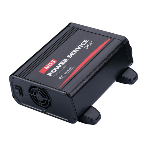
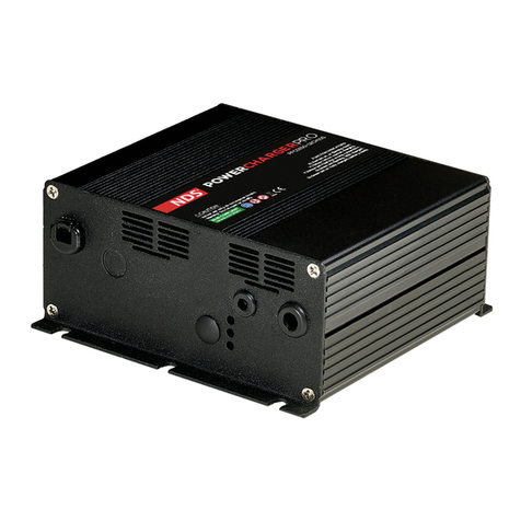
NDS Dometic PSB12-40 User manual

POWER & CONTROL
CHARGER
PSB12-40, PSB12-80, PSB24-40, PSB24-60, PSB12/24-20, PSB12/24-40,
PSB24/12-40, PSB24/12-80
EN Charger
Installation and Operating manual...............................6
DE Ladegerät
Montage- und Bedienungsanleitung......................... 24
FR Chargeur
Instructions de montage et de service....................... 42
ES Cargador
Instrucciones de montaje y de uso............................ 60
PT Carregador de baterias
Instruções de montagem e manual de instruções........ 78
IT Caricabatterie
Istruzioni di montaggio e d’uso................................ 96
NL Oplader
Montagehandleiding en gebruiksaanwijzing............. 114
DA Oplader
Monterings- og betjeningsvejledning.......................132
SV Laddare
Monterings- och bruksanvisning..............................150
NO Lader
Monterings- og bruksanvisning............................... 168
FI Laturi
Asennus- ja käyttöohje........................................... 186
PL Ładowarka
Instrukcja montażu i obsługi................................... 204
SK Nabíjačka
Návod na montáž a uvedenie do prevádzky............. 223
CS Nabíječka
Návod k montáži a obsluze.....................................241
HU Akkumulátor töltőkészülék
Szerelési és használati útmutató..............................259
HR Punjač
Upute za montažu i rukovanje.................................277
TR Şarj cihazı
Montaj ve Kullanım Kılavuzu................................... 295
SL Polnilnik
Navodila zamontažo in uporabo.............................313
RO Încărcător
Manual de instalare şi de utilizare............................ 331
BG Зарядно устройство
Ръководство за инсталация и работа.......................349
ET Laadija
Paigaldus- ja kasutusjuhend....................................368
EL Φορτιστής
Εγχειρίδιο τοποθέτησης και χρήσης.................... 386
LT Įkroviklis
Montavimo ir naudojimo vadovas........................... 406
LV Lādētājs
Uzstādīšanas un lietošanas rokasgrāmata..................424

Copyright
© 2023 Dometic Group. The visual appearance of the contents of this manual is protected by copyright and design
law. The underlying technical design and the products contained herein may be protected by design, patent or be
patent pending. The trademarks mentioned in this manual belong to Dometic Sweden AB. All rights are reserved.

EN
List of Figures
23
4
5
6
7
8
9
10
1
1 2 3 4 5 6 7
1

EN
1.
3.
2.
2

EN
D+
+–
+–
1
2
D+
125 A (12 V)
80 A (24 V)
100 A (12 V)
70 A (24 V)
+–
+–
1
3

EN
D+
80 A
100 A
+–
+–
80 A
12
3
D+
B1
B2
D+
AC/DC
125 A
100 A
+–
+–
80 A
12
3
4
4

EN
D+
80 A
70 A
+–+–
+– +–
80 A
12
3
D+
AC/DC
80 A
70 A
80 A
+–+–
+– +–
B1
B2
D+
12
3
4
5

EN
English
1Important notes..............................................................................................................................6
2Explanation of symbols....................................................................................................................6
3General safety instructions............................................................................................................... 7
4Scope of delivery.......................................................................................................................... 10
5Intended use................................................................................................................................ 10
6Target Group.................................................................................................................................11
7Technical description......................................................................................................................11
8Installation....................................................................................................................................14
9Configuration............................................................................................................................... 17
10 Operation.................................................................................................................................... 21
11 Cleaning...................................................................................................................................... 21
12 Troubleshooting............................................................................................................................21
13 Disposal...................................................................................................................................... 22
14 Warranty......................................................................................................................................22
15 Technical data.............................................................................................................................. 22
1 Important notes
Please read these instructions carefully and follow all instructions, guidelines, and warnings included in this product manual in order to ensure that you install, use, and maintain
the product properly at all times. These instructions MUST stay with this product.
By using the product, you hereby confirm that you have read all instructions, guidelines, and warnings carefully and that you understand and agree to abide by the terms and
conditions as set forth herein. You agree to use this product only for the intended purpose and application and in accordance with the instructions, guidelines, and warnings as
set forth in this product manual as well as in accordance with all applicable laws and regulations. A failure to read and follow the instructions and warnings set forth herein may
result in an injury to yourself and others, damage to your product or damage to other property in the vicinity. This product manual, including the instructions, guidelines, and
warnings, and related documentation, may be subject to changes and updates. For up-to-date product information, please visit documents.dometic.com.
2 Explanation of symbols
DANGER!
Indicates a hazardous situation that, if not avoided, will result in death or serious injury.
WARNING!
Indicates a hazardous situation that, if not avoided, will result in death or serious injury.
CAUTION!
Indicates a hazardous situation that, if not avoided, could result in minor or moderate injury.
NOTICE!
Indicates a hazardous situation that, if not avoided, could result in minor or moderate injury.
6


EN
Note Supplementary information for operating the product.
3 General safety instructions
Also observe the safety instructions and stipulations issued by the vehicle manufacturer and autho-
rized workshops.
WARNING! Electrocution hazard
Failure to obey these warnings could result in death or serious injury.
• Installation and removal of the battery charger may only be carried out by qualified personnel.
• Do not operate the device if it is visibly damaged.
• If this device's power cable is damaged, the power cable must be replaced by the manufacturer, a
service agent or a similarly qualified person in order to prevent safety hazards.
• This device may only be repaired by qualified personnel. Improper repairs can lead to considerable
hazards.
• If you disassemble the device: Detach all connections. Ensure that no voltage is present on any of
the inputs and outputs.
• Do not use the device in wet conditions or submerge in any liquid. Store in a dry place.
• Only use accessories that are recommended by the manufacturer.
• Do not modify or adapt any of the components in any way.
Disconnect the device from the power supply:
• Before each cleaning and maintenance
• After every use
• Before changing a fuse
• Before carrying out electrical welding work or work on the electrical system
WARNING! Health hazard
Failure to obey these warnings could result in death or serious injury.
• This device can be used by children aged from 8 years and above and persons with reduced physi-
cal, sensory or mental capabilities or lack of experience and know-ledge if they have been given su-
pervision or instruction concerning use of the device in a safe way and understand the hazards in-
volved.
•Electrical devices are not toys. Always keep and use the device out of the reach of very young
children.
• Children must be supervised to ensure that they do not play with the device.
• Cleaning and user maintenance shall not be made by children without supervision.
NOTICE! Damage hazard
• Before start-up, check that the voltage specification on the data plate is the same as that of the pow-
er supply.
• Ensure that other objects cannot cause a short circuit at the contacts of the device.
• Ensure that the negative and positive poles never come into contact.
7

EN
3.1 Installing the device safely
DANGER! Explosion hazard
Failure to obey these warnings will result in death or serious injury.
Never mount the device in areas where there is a risk of gas or dust explosion.
WARNING! Risk of injury
Failure to obey these warnings could result in death or serious injury.
• Ensure that the device is standing firmly. The device must be set up and fastened in such a way that
it cannot tip over or fall down.
• When positioning the device, ensure that all cables are suitably secured to avoid any form of trip
hazard.
NOTICE! Damage hazard
• Do not place the battery charger near heat sources (heaters, direct sunlight, gas ovens, etc.).
• Set up the device in a dry location where it is protected against splashing water.
3.2 Operating the device safely
DANGER! Electrocution hazard
Failure to obey these warnings will result in death or serious injury.
Do not touch exposed cables with your bare hands. This applies especially when operating the device
from the AC mains.
WARNING! Explosion hazard
Only use the device in closed, well-ventilated rooms.
Do not operate the device under the following conditions:
• In salty, wet or damp environments
• In the vicinity of corrosive fumes
• In the vicinity of combustible materials
• In areas where there is a danger of explosions
WARNING! Electrocution hazard
• Before starting the device, ensure that the power supply line and the plug are dry and the plug is
free from rust or dirt.
• Always disconnect the power supply when working on the device.
• Observe that parts of the device may still conduct voltage even if the fuse has blown.
• Do not disconnect any cables when the device is still in use.
NOTICE! Damage hazard
• Ensure that the air inlets and outlets of the device are not covered.
• Ensure a good ventilation.
• Never pull the plug out of the socket by the connection cable.
• The device shall not to be exposed to rain.
8

EN
3.3 Safety precautions when handling batteries
WARNING! Risk of injury
• Batteries contain aggressive and caustic acids. Avoid battery fluid coming into contact with your
body. If your skin does come into contact with battery fluid, wash that part of your body thoroughly
with water. If you sustain any injuries from acids, contact a doctor immediately.
• When working on batteries, do not wear any metal objects such as watches or rings. Lead acid bat-
teries can cause short circuits which can cause serious injuries.
• Only use insulated tools.
• Do not place any metal parts on the battery.
• Wear goggles and protective clothing when working on batteries. Do not touch your eyes when
working on batteries.
• Do not use defective batteries.
WARNING! Health hazard
Keep the battery out of the reach of children.
CAUTION! Electrocution hazard
• Keep the battery away from water.
• Avoid short circuits.
• Avoid clothing rubbing against the battery.
• Wear antistatic clothing when handling the battery.
CAUTION! Explosion hazard
• Do not place the battery in a area with flammable liquids or gases.
• Never attempt to charge a frozen or defective battery. Place the battery in a frost-free area and wait
until the battery has acclimatised to the ambient temperature. Then start the charging process.
• Do not smoke, use an open flame, or cause sparking near the engine or a battery.
• Keep the battery away from heat sources.
NOTICE! Damage hazard
• Only use rechargeable batteries.
• Prevent any metal parts from falling on the battery. This can cause sparks or short-circuit the battery
and other electrical parts.
• Ensure that the polarity is correct when connecting the battery.
• Follow the instructions of the battery manufacturer and those of the manufacturer of the system or
vehicle in which the battery is used.
• If the battery has to be removed, first disconnect the ground connection. Disconnect all connec-
tions and all consumers from the battery before removing it.
• Only store fully charged batteries. Recharge stored batteries regularly.
• Do not carry the battery by its terminals.
9

EN
Safety precautions when handling lithium batteries
CAUTION! Risk of injury
Only use batteries with integrated battery management system and cell balancing.
NOTICE! Damage hazard
• Only install the battery in environments with an ambient temperature of at least 0 °C.
• Avoid deep discharge of the batteries.
Safety precautions when handling lead acid batteries
CAUTION! Health hazard
The water-acid liquid inside the battery can evaporate and cause an acidic odor. Use the battery only in a
well-ventilated area.
NOTICE! Damage hazard
• The battery is not sealed. Do not turn the battery on its side or upside down. Place the battery on a
horizontal surface.
• Check the acid level for open lead acid batteries regularly.
• Immediately recharge deeply discharged lead acid batteries to avoid sulfation.
4 Scope of delivery
• Charger
• Fuse, 80 A
• Fuse, 110 A
5 Intended use
The battery charger is intended to monitor and charge house batteries in recreational vehicles by the alternator while
driving.
The charger is intended to charge the following battery types:
• Lead acid batteries
• Lead gel batteries
• Absorbed glass mat (AGM) batteries
• LiFePO4 batteries
The battery charger is not intended to charge other types of batteries (e. g. NiCd, NiMH, etc.).
The charger is suitable for:
• Installation in recreational vehicles
• Stationary or mobile use
• Indoor use
10

EN
The charger is not suitable for:
• Mains operation
• Outdoor use
This product is only suitable for the intended purpose and application in accordance with these instructions.
This manual provides information that is necessary for proper installation and/or operation of the product. Poor in-
stallation and/or improper operating or maintenance will result in unsatisfactory performance and a possible failure.
The manufacturer accepts no liability for any injury or damage to the product resulting from:
• Incorrect assembly or connection, including excess voltage
• Incorrect maintenance or use of spare parts other than original spare parts provided by the manufacturer
• Alterations to the product without express permission from the manufacturer
• Use for purposes other than those described in this manual
Dometic reserves the right to change product appearance and product specifications.
6 Target Group
The electrical power supply must be connected by a qualified electrician who has demonstrated skill and
knowledge related to the construction and operation of electrical equipment and installations, and who
is familiar with the applicable regulations of the country in which the equipment is to be installed and/or
used, and has received safety training to identify and avoid the hazards involved.
7 Technical description
General description
The charger charges the house battery by the alternator with the following charging current while driving:
• PSB12-40: 40 A
• PSB12-80: 80 A
• PSB24-40: 40 A
• PSB24-60: 60 A
• PSB12/24-20: 20 A
• PSB12/24-40: 40 A
• PSB24/12-40: 40 A
• PSB24/12-80: 80 A
The charger can be adapted to different battery types via DIP switches.
The charger offers the following functions:
• Microprocessor-controlled, temperature-compensated IU0U charging programs for various battery types
• Buffer operation: Compliance with the charging characteristics even when the battery is charged with con-
sumers connected
• On-board mains suppression filter: Ensures parallel operation of the charger with other charging sources, for
example mains supply chargers, solar systems, or generators
11

EN
• Automatic compensation of voltage loss caused by the charging cable length (house battery)
• AUX connection usable for controller output, split-charge relay, or electrical devices (only PSB12-40,
PSB12-80, PSB24-40, PSB24-60)
The charger has the following protective mechanisms:
• High voltage protection
• Low voltage protection
• High temperature protection
• Low temperature protection (only LiFePO4 batteries)
• Battery overcharge protection (only with optional tempertaure sensors)
• Reverse current protection
• Protection against short circuit
• Reverse polarity protection (only for house battery connection)
The charger can be connected to the DTB01 display (optional) for remote control. If a Bluetooth N-BUS device is
present in the N-BUS network, the mobile app can be used for controlling the charger.
A temperature sensor (optional) can be connected to monitor the battery temperature during the charging process.
Description of the device
fig. on page1
Table 1: Connections and controls
No. Designation Description
1 N-BUS N-BUS/CI-BUS connection 1
2 N-BUS N-BUS/CI-BUS connection 2
3 – Status LED
4 AUX AUX connection
5 GND Connection to chassis or negative pole of the house battery
6 OUT Connection to positive pole of house battery
7 INPUT Connection to positive pole of starting battery
8– Terminal block for signal cables
9 – DIP switches for settings
10 ON / OFF/ Remote Switch (ON/OFF/Remote control)
12

EN
Table 2: Status LED
LED Description
Red Battery charging.
Voltage higher than 12 V or 24 V (depending on the model).
Orange Battery deep discharged.
Voltage lower than 12 V or 24 V in charging phase 1 and 2 (depending on the model).
Green Battery completely charged, maintenance mode.
fig. on page1
Table 3: Terminal block
PIN Designation Description
1 D+ terminal Input for D+ signal of the alternator or ignition lock signal (terminal 15)
2 Sense + Signal (+) output voltage
3 Sense - Signal (-) output voltage
4 Temp 1
5 Temp 2
Connection for temperature sensor (optional)
6 – Not used
7 – Remote charging status signal
Battery charging function
A main charging cycle of the house battery is initiated in the following situations:
• After a standstill of the alternator
• After falling below the reset voltage
fig. on page2
In all charging phases, almost the entire possible charger current is available for the additional supply of DC loads
without discharging the battery.
The charging characteristics for fully automated continuous operation without monitoring are referred to as IU0U
characteristics.
1, 2: Analysis phase (Recondition and pulse)
The battery is deeply discharged (> 10 %). The battery charge is analyzed with increasing charging current.
13

EN
3, 4: I phase (Constant current phase – Bulk)
At the beginning of the charging process, the empty battery is constantly charged with half of the the maximum
charging current (50 %). The charging current increases to 100 % after 1 min. Deeply discharged lead batteries are
charged with reduced charging current until the battery voltage exceeds 8 V. The duration of the I phase depends
on the state of the battery, the load from the consumers and the state of charge. For safety reasons the I phase is ter-
minated after a maximum of 15 h (in case of battery cell defects or similar).
5: U1 phase (Constant voltage phase – Absorption)
The U1 phase starts when the battery is fully loaded. The charging current is reduced. During the U1 phase, the bat-
tery voltage is kept constant at a high level. The duration of the U1 phase depends on the battery type and the depth
of discharge.
6: Desulfation phase
A constant current will be delivered, allowing the battery voltage to rise independently to the maximum value. The
desulfation phase is not used for LiFePO4 batteries.
7: U2 phase (Trickle charging – Float)
The U2 phase serves to maintain the battery capacity (100 %). The U2 phase runs at lowered charging voltage and
variable current. If DC loads are connected, they are powered by the device. Only if the power required exceeds the
capacity of the device, this surplus power is provided by the battery. The battery then is discharged until the device
re-enters the I phase and charges the battery.The U2 phase is limited to between 24 and 48 h depending on the bat-
tery type.
8 Installation
Before installation
Observe the following instructions when selecting an installation location:
• Ensure that the mounting surface is solid and level.
• Choose an well ventilated installation location to avoid overheating.
• Observe a distance of 10 cm to the ventilation openings of the cooling fan.
Choose a suitable installation location to connect the power cables to the battery.
Mounting the charger
NOTICE! Damage hazard
Before drilling any holes, ensure that no electrical cables or other parts of the vehicle can be damaged by
drilling, sawing and filing.
1. Ensure that the vehicle's engine and the battery chargers are switched off.
2. Set the switch to the OFF position.
3. Screw the charger to the mounting surface.
fig. on page2
14

EN
Determining the cable cross-section
The cable cross-section of the power cables depends on the model and on the cable length.
Table 4: Cable cross-section
Model I <2m 2 m < l < 4ml > 4m
Input Output Input Output Input Output
PSB12-40 16 mm² 16 mm² 25 mm² 25 mm² 35 mm² 35 mm²
PSB12-80 35 mm² 35 mm² 50 mm² 50 mm² 100 mm² 100 mm²
PSB24-40 16 mm² 16 mm² 25 mm² 25 mm² 35 mm² 35 mm²
PSB24-60 35 mm² 25 mm² 50 mm² 35 mm² 100 mm² 50 mm²
PSB12/24-20 25 mm² 16 mm² 35 mm² 16 mm² 100 mm² 25 mm²
PSB12/24-40 35 mm² 16 mm² 50 mm² 25 mm² 100 mm² 35 mm²
PSB24/12-40 16 mm² 16 mm² 25 mm² 25 mm² 35 mm² 35 mm²
PSB24/12-80 35 mm² 35 mm² 50 mm² 50 mm² 100 mm² 100 mm²
Select power cables of the suitable cross-section.
Connecting the charger
WARNING! Electrocution hazard
Observe the recommended cable crosssections, cable lengths and fuse.
CAUTION! Fire hazard
Place the fuses near the batteries to protect the charger from short circuits and possible burning.
NOTICE! Damage hazard
Do not reverse the polarity.
Observe the following instructions when connecting the charger:
• Select the appropriate connection variant, Connection variant A, Connection variant B, Connection variant C,
Connection variant D, Connection variant E.
• Use suitable measuring instruments:
• Multimeter with DC voltage measurement, 200 V or autoscale
• Amperometric clamp with direct measurement (100 A scale or higher)
• Always connect the charger before connecting the batteries.
• Do not use ferrules. Strip the cable ends as follows:
• Signal cable 12 mm (0.5 mm²… 1.5 mm²)
• Charging cable 15 mm
fig. on page3
1. Connect the negative pole of the starting battery to GND.
15

EN
2. Connect the fuse holder to the positive pole of the starter battery.
3. Connect the other end of the fuse holder to INPUT.
4. Insert a fuse into the fuse holder.
5. Connect the fuse holder to the positive pole of the house battery .
6. Connect the other end of the fuse holder to OUT.
7. Insert the output fuse into the fuse holder.
8. Connect the D+ or ignition+ signal wire to PIN 1 of the terminal block.
9. Optional: Connect the output voltage control positive signal cable (+SENSE) from PIN 2 of the terminal block
to the positive pole of the house battery, and the negative signal cable (-SENSE) from PIN 3 of the terminal block
to the negative pole of the house, using a cable with 1 mm² cross-section. This connection will reduce the volt-
age drop on power cables during the charging process by an electronical control device.
10. Optional, only applicable to models PSB12-40, PSB12-80, PSB24-40, PSB24-60: Connect a device
to the AUX connection, see connection diagram, Connection variant B, Connection variant C, Connection vari
ant D, Connection variant E.
Connection variant A
Connection variant for basic installation with 12 V or 24 V batteries.
To connect the battery charger proceed as shown.
fig. on page3
Connection variant B
Connection variant for vehicles without control unit or with a split charge relay.
To connect the battery charger proceed as shown.
fig. on page4
Connection variant C
Connection variant for vehicles with control unit already installed.
To connect the battery charger proceed as shown.
fig. on page4
Connection variant D
Connection variant for a 24 V system for vehicles without control unit or with a split charge relay.
To connect the battery charger proceed as shown.
fig. on page5
Connection variant E
Connection variant for a 24 V system for vehicles with control unit already installed.
To connect the battery charger proceed as shown.
fig. on page5
16

EN
9 Configuration
NOTICE! Damage hazard
Use a small screwdriver to carefully move the DIP switches to the required position.
Setting up the alternator type
This function can only be activated by the DIP switch, not by an external controller (optional DTB01 display or mobile
app).
Slide the DIP switch according to your vehicle alternator type.
Table 5: Alternator configuration
DIP switch position (gray) Function
activated 13.3 V
Standard alternator
deactivated 12.7 V
activated 11.7 V
Smart alternator
deactivated 11.25 V
Setting the charging program
NOTICE! Damage hazard
Only use batteries that are suitable for the specified charging voltage.
Select the charging program suitable or the type of house battery used based on the battery manufacturer's specifi-
cations, the information on the charging curves (see Battery charging function) and the technical data (see Technical
data ). The specified charging times apply to an average ambient temperature of 20 °C.
Setting charging programm can be activated by the DIP switch on the charger or, if a Bluetooth N-BUS device is
present in the N-BUS network, via the DTB01 display or via the mobile app.
17

EN
Slide the DIP switches to the position shown in the table below to set the charging program for the respective
type of house battery.
Table 6: Charging curve configuration
Function
Max. voltage (Uabs) Float voltage (Ufloat) Max. desulfation volt-
age
DIP switch po-
sition (gray)
Charging
program
12 V 24 V 12 V 24 V 12 V 24 V
Lead gel bat-
teries
14.2 V 28.4 V 13.5 V 27 V OFF OFF
Wet batteries 14.4 V 28.8 V 13.8 V 27.6 V OFF OFF
AGM/1 bat-
teries
14.7 V 29.4 V 13.6 V 27.2 V OFF OFF
AGM/2 bat-
teries
14.7 V 29.4 V 13.6 V 27.2 V 15.6 V 31.2 V
LiFePO4/1
batteries
14.5 V 29 V 13.8 V 27.6 V OFF OFF
LiFePO4/2
batteries
14.5 V 29 V OFF OFF OFF OFF
LiFePO4/3
batteries
14.2 V 28.4 V 13.6 V 27.2 V OFF OFF
18
This manual suits for next models
7
Table of contents
Languages:
Other NDS Batteries Charger manuals

NDS
NDS POWERCHARGERPRO PFC0150-12CH10S User manual

NDS
NDS SMARTCHARGER SCS15 User manual

NDS
NDS SMARTCHARGER SCM25 User manual

NDS
NDS POWERSERVICE PLUS 25 User manual

NDS
NDS SMARTCHARGER SCS2 User manual

NDS
NDS POWERSERVICEPSB PSB 12-40 User manual

NDS
NDS POWERSERVICE PLUS 25 User manual

NDS
NDS SCE320 User manual

NDS
NDS PF12CH25S – 12V 25A User manual