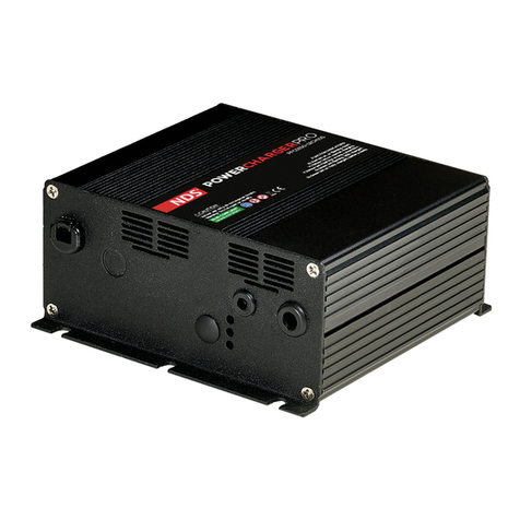
NDS PF12CH25S – 12V 25A User manual

Power Charger Pro
Professional Power Chargers
Operation Manual

INTRODUCTION
This manual contains important operating and safety instructions, before starting to
use the battery charger it is important to read and understand the safety instructions in
this manual.
Safety notes
–Before each use please check the battery charger, the connection cable and the
connector. If any malfunction is detected do not use it! It is strictly forbidden to
open the device. Repairs may only be carried out by qualified technicians using
original spare parts. A charger, a cable and or a damaged connector increases
the risk of fatal electric shocks.
–Do not place the charger on highly flammable surfaces or environments (ex .:
paper, cloth etc ...). The overheating of the device during the charging phases
can increase the risk of fire.
–During operation the device should be placed in a well-ventilated place.
–If the power supply cable is damaged it must be replaced by a qualified
technician to eliminate the risk of accidents.
WARNING
– Never charge a cold or non-rechargeable battery!
–
Keep the device out of the reach of children
–
The device must be protected from sunlight or direct heat sources to prevent
overheating.
–
To reduce the risk of malfunctions do not block the ventilation bores.
–
DO NOT install the unit in a sealed environment, otherwise it may overheat.
–
To
avoid
the
risk
of
electric
shock
and
or
fire,
make
sure
that
the
power
supply system is in good condition.
–
DO
NOT
use
the
charger
with
damaged
cables
and
or
with
inadequate
section.
–
DO NOT use the battery charger in an environment with high humidity or in
direct contact with splashes of water and or other liquid or in the rain.
1

FEATURES
The photos of the product in this manual are only for reference with the purpose of
explanation; the product you have purchased may be different.
This smart battery charger can be used to charge flooded, Gel
and AGM batteries.
15Amp & 20Amp models are also suitable for LiFePO4 (lithium) batteries.
Please
read
carefully the label on the product and verify that the default settings of the
charging
algorithm are appropriate for the type of battery to be charged.
Always keep this user manual near the charger for easy reference on
essential safety,
use and maintenance information.
The information in this manual may be subject to modifications without any prior
notification.
NDS Energy
reserves the right to make changes and improvements to the product at
any time without notice and without obligation to relate these changes to previously
distributed devices.
Smart battery charger (main features):
•High frequency and high-tech battery charger
•Universal Input 100 to 240VAC with a highly advanced PFC
•Charging curves entirely controlled by micro controller
•Designed to have high efficiency in all operating conditions
•Thermal protection against overheating
•Operating status indicated by 3 LED (Green - Yellow - Red)
OPTIONAL
•LEDs extension for a remote indication
•Soft start and automatic reset of the charging curve when a new battery is
connected.
•Ability to change the charging curves by DIP-SWITCHES
•Ability to change the charging current by DIP-SWITCHES
•Equipped with a Normally Open (NO) relay for main line presence warning.
NOTES
All options can be added and are available on the charger only upon request.
Check the label of the product to verify the features and options in your device.
All NDS smart Battery Chargers have the PFC circuit with universal input.
2

Before installing and using the charger, please set the most suitable charging curve
for the type of battery to be charged. The charger is equipped with
DIP-SWITCHES to select various charging curves, as shown in the following table:
DP1 DP2 PHASES DESCRIPTION
OFF OFF IUIa AGM For AGM batteries
OFF ON IUIa Acd For Lead Acid Flooded traction batteries
ON OFF IUUa Generic curve for GEL and AGM batteries
(Default setting)
ON ON IU LiFePO4 For LiFePO4 lithium battery
ON ON IUIa - GEL For GEL batteries and all Lead Acid Flooded
(Only for model 12V - 10A)
The DIP-SWITCHES are behind a black plastic cover on the front panel of the
device, so in one of the two shorter sides.
In some models, there are 4 DIP-SWITCHES but only the two switches on the left
are used
FUNCTIONING
After setting the DIP-SWITCHES of the charger, by connecting it to the battery and
to the mains, the device signals the operating status with LEDs of different colors.
According
to
the
model there are
3
or
5
LED
indicators,
as
shown
in
the
following pictures:
The LEDs on the charger have the following meanings:
3
DP1 DP2
ON
ON
DP3 DP4
ON
ON
CHARGING CURVE SELECTION

Battery charger with 3 LEDs
LED status Indication
Constant or flashing
RED
Battery with inverted poles
or too high voltage
Constant YELLOW On charge
Flashing YELLOW Battery disconnected or too
low voltage
Constant GREEN Battery charged
Battery charger with 5 LEDs
LED status Indication
Flashing RED Battery with too high voltage
Constant RED Battery with inveted poles
Constant ORANGE Battery disconnected
Flashing ORANGE Self-diagnosis of the charger failed
Constant ORANGE +
YELLOW
On charge
Constant YELLOW Capacity of the battery on charge
Constant GREEN Battery charged
Some devices have two pairs of output cables that may also have the same color but
of different section:
The pair of cables of larger section is the power output of the
charger,
which
must
be
connected
to
the
battery,
while
the
other
pair
consists of a dry contact of a NORMALLY OPEN relay. Connecting one cable to
the battery voltage, the Normally Open contact, can be used to turn on a 12V lamp
(or LED) when the main line is connected.
If the pair of cables with the larger section is BROWN BLUE color, the
POSITIVE is the BROWN cable.
The cooling fan fans are electronically controlled by the microcontroller which
decides the power and speed according to the conditions of the internal and
environment temperatures.
4

5
PF12CH25S – 12V 25A
Description
Technical Features
Input voltage
100VAC – 240VAC ±10% Universal
Frequency
50Hz - 60Hz
Output - Boost Charge
14,4V (2,4V Cell)
Output - Float Charge
13,5V – 13,9V (2,27V Cell)
Output current
25A ±0,5A
Short-circuit protection
Auto reset at the end of short-circuit condition
Reverse polarity protection
Auto reset at the end of reverse polarity condition
Additional protections
Safe connection without sparking on output and input
Thermal protection against over temperature
Dimensions L223.2 x W128 x H56.5 mm
Weight 2,12kg (cables excluded)
MODELS
PF12CH12S – 12V 15A
Description
Technical Features
Input voltage
100VAC – 240VAC ±10% Universal
Frequency
50Hz - 60Hz
Output - Boost Charge
14,4V (2,4V Cell)
Output - Float Charge
13,5V – 13,9V (2,27V Cell)
Output current
15A ±0,5A
Short-circuit protection
Auto reset at the end of short-circuit condition
Reverse polarity protection
Auto reset at the end of reverse polarity condition
Additional protections
Safe connection without sparking on output and input
Thermal protection against over temperature
Dimensions L223.2 x W128 x H56.5 mm
Weight 2,12kg (cables excluded)

SYMBOLS
Warning, handle this device very carefully
Read carefully and follow the instructions for use, maintenance and
safety before using the battery charger. A use other than that indicated
in the manual or not following these instructions may result in
electric shock, fire and or serious injury.
Device for use in enclosed spaces protected from rain and splashes of
water and liquids in general. The introduction of liquids into the
battery charger may result in electric shock.
The battery charger contains dangerous substances for the
environment, so it is not allowed the free product disposal, but it is
necessary to use the appropriate collection centers organized by the
local municipalities or contact the manufacturer directly.
Respecting this rule protects the environment.
Do not use the device in flammable environments where a spark
could cause a fire or the spreading of flames.
Do not open the device, electric shock hazard
CE marking certifying the conformity of the device
Conformity marking obteined by TUV SUD
ETL Conformity obtained for the standards UL1012, UL1564 e CSA
C22.2 e NO.107.
6

WARRANTY
The manufacturer guarantees the proper functioning of the Power Charger Pro and
undertakes to make the free replacement of parts that deteriorate for construction
defects within 24 months from the date of purchase, as evidenced by the validation
card (to be filled in all its part and send back to the manufacturer).
The defects resulting from improper installation, use, tampering or negligence shall
not be covered by warranty.
Furthermore, we assume no liability for any direct or indirect damages.
The Power Charger Pro returned, even if under warranty, will have to be shipped
“Freight paid” and shall be returned on as “Freight collect”.
The certificate of warranty shall be valid only if accompanied by a official receipt or
delivery document.
Mod...............................................Serial n................................................
Purchase date ........................................
Stamp and signature of the reseller
7
This manual suits for next models
1
Table of contents
Other NDS Batteries Charger manuals

NDS
NDS SCE320 User manual

NDS
NDS SMARTCHARGER SCS2 User manual

NDS
NDS SMARTCHARGER SCM25 User manual

NDS
NDS POWERSERVICE PLUS 25 User manual

NDS
NDS POWERSERVICE PLUS 25 User manual

NDS
NDS POWERCHARGERPRO PFC0150-12CH10S User manual

NDS
NDS SMARTCHARGER SCS15 User manual

NDS
NDS POWERSERVICEPSB PSB 12-40 User manual

NDS
NDS Dometic PSB12-40 User manual