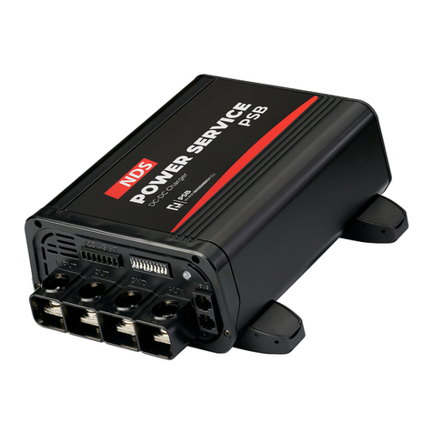
NDS POWERSERVICEPSB PSB 12-40 User manual

1
POWERSERVICEPSB
User Manual
VALID FOR THE FOLLOWING MODELS
PSB 12-40
PSB 12-80
PSB 12/24-20
PSB 12/24-40
ENGLISH
PSB 24-30
PSB 24-60
PSB 24/12-40
PSB 24/12-80

2
This electronic device is subject to the European
Directive 2012/19/EU. according to the local waste
disposal rules, do not dispose of old products with
normal household waste. The proper disposal of
products that can no longer be used prevents potential
negative consequences for the environment and for the
population.
INSTRUCTIONS FOR THE PROPER DISPOSAL!

INDEX
1. safety instructions 4
2. Package contents 5
3. DESCRIPTION 5
4. STRUcture 8
5. Controllers 10
6. Installation 11
7. aux connection (ref. D) 13
8. alternator type setup 14
9. Charging curve setup 15
10.Extra selections 17
11. Terminal Block (ref. h) 19
12.Led indicator (Ref. I) 20
13.three way Switch (REF.l) 21
14.external fuse 22
15.Power cable section 22
16.System operation check 23
17. MAINTENANCE 24
18.Fuse replacement 25
19.Technical details 25
20.WIRING DIAGRAMS samples 28
21.WARRANTY 34

1. SAFETY INSTRUCTIONS
• Child Safety: keep the device Out of Reach.
• Check the device and connectors integrity.
• Always choose a well ventilated area to avoid
overheating and possible fires.
• Do not place the device on highly flammable
surfaces or environments (eg: paper, cloth, etc.).
• Do not cover the cooling fan on the side.
• Do not install the device near flooded batteries: they
produce flammable, corrosive and explosive gas
while working, and it can damage the product.
• Protect the device from sunlight or direct sources of
heat.
• To avoid malfunctions, DO NOT install and use the
device in very humid environments, in contact with
water splashes, various liquids, or exposed to rain.
• To avoid risk of electric shock and/or fire, the
vehicle's fuel system must be in good condition.
• In case of damaged connecting cables or
inadequate section, immediately replace them with
suitable cables as specified by this manual or by a
qualified electrician.
• In case of anomalies in the conformity of the
product do not use it! it is strictly forbidden to open
the device. Repairs may only be carried out by
qualified technical personnel using original spare
parts.
• Keep the instruction manual near the device for
easy access to the essential safety, use and
maintenance information.
• The information contained in this manual may be
changed without notice. NDS Energy s.r.l. reserves
the right to make changes and improvements to the
product at any time without notice and without
obligation to apply these changes to the devices
previously distributed.
• Product images are purely indicative and may
therefore not be fully representative of the
characteristics of the product, differing in colour, size
or accessories.
4

2. PACKAGE CONTENTS
Check the contents of the package:
1x Power Service DC-DC Charger
1x STRIP HSB fuse 80A
1x STRIP HSB fuse 110A
3. DESCRIPTION
POWERSERVICEPSB, the best choice for energy
independence!
With the POWERSERVICEPSB you can charge you
batteries up to 80A in a very small size, this means that
you will arrive at your destination with 100% charged
batteries to power up the appliances like the air
conditioner or the heater.
Unlike the vehicle alternator, the POWERSERVICEPSB
is a real battery charger with proper charging curves for
every commercial leisure battery: Lithium (LiFePO4),
AGM, Gel, Wet. With the OPTICHARGE charging
algorithm, developed by NDS, your batteries will be
always perfectly charged and maintained for a long
lasting life. After starting the vehicle engine, the
POWERSERVICEPSB will receive the D+ (or Ignition+)
5
NOTE
It is indispensable, for a correct installation, to be equipped
with suitable measuring instruments:
• Multimeter with DC voltage measurement (20V or autoscale)
and continuity measurement.
• Amperometric clamp with direct current measurement (40A
scale and higher).

signal and start monitoring the Starter battery voltage
to check the State of Charge. With a voltage higher
than 13.3V, or 26.6V for 24-24 versions, the
POWERSERVICEPSB will start charging the leisure
batteries.
During the charging phase, the starter battery voltage
will be constantly monitored to avoid any supply
problem or overload to the alternator. If necessary, the
POWERSERVICEPSB will reduce the output current or
stop the charge completely. The output current will be
limited if the POWERSERVICEPSB detects an active
signal D+ (or Ignition+) and a starter battery voltage
below 13V.
The POWERSERVICEPSB switches off completely if the
starter battery voltage drops to 12.8V and the signal D+
or Ignition+ (ie engine shutdown) is no longer detected
(different thresholds for Smart Alternator Euro6).
The AUX connection makes installation simple and
intuitive, even with an existing electrical system: the
Control Unit, or any other appliances system, installed
on the leisure battery, can be switched to the AUX
connection without changing the wiring system. it’s
quick and easy!
POWERSERVICEPSB is fitted with the new N-BUS
communication and connection protocol: now you
can connect and control all the allowed devices with a
simple cable, and manage them with one control only,
the DTB01 touch screen display. If there is a N-BUS
bluetooth device in the same network you can also use
the NDS mobile App for iOS and Android.
6

MAIN FEATURES
•Up to 80A of charge in a very small size.
•High efficiency, up to 97%.
•Charge management with microcontroller.
•7 charging steps with OPTICHARGE firmware.
•Selectable charging curve: AGM, Gel, Wet, lithium
(LiFePO4).
•AUX connection for maximum charging power to the
leisure batteries, and easy installation even with
existing and preinstalled systems.
•Split-Charge relay separates Starter and leisure
batteries.
•Compatible with Smart Alternator Euro 6 vehicles.
•Alternator protection (in case of overload).
•Fan speed regulated by temperature and operating
power, for a silent and efficient device.
•Electronic and fuse protections.
•Emergency switch reverts to original charging
system in case of failure.
•Battery temperature sensor for battery
temperature monitoring during the charge.
•Output voltage sensing during the
charge, directly on the battery poles, to always supply
the maximum power and correct voltage level.
•Quiet, compact and easy to install.
7

4. STRUCTURE
8
FRONT CONNECTION
REFERENCE
FUNCTION
A
Starter battery positive pole
B
Leisure battery positive pole
C
Batteries and vehicle negative connections
D
AUX connection
E
N-BUS connection 1
F
N-BUS connection 2
G
Terminal block connector (Fig. 3)
H
Dip-switch selector (Fig. 4)
I
Led indicator (Chapter 12)
Fig.1
AB C D
E
HI
G
F

9
BACK CONNECTION
REFERENCE
FUNCTION
L
ON / OFF / Remote Switch
Fig.2
L
DIP SWITCH SETUP (REF. G)
DIP SWITCH
FUNCTION
1
Alternator type setup (Traditional or Smart Euro6)
2-3-4
Charging curve selection
5
Silent mode ON/OFF
6
Input current limit ON/OFF
7-8
Output current limit level selection
9-10
Not used
Fig.3

5. CONTROLLERS
You can control the POWERSERVICEPSB and all N-
BUS devices with a single Touch Screen full color
Display (DTB01), or with the mobile app if there is, at
least, one NDS device with Bluetooth within the N-BUS
network. Bluetooth devices are e.g. SUNCONTROL2
(models with Bluetooth) and TEMPRA Lithium Battery
(all models). The mobile app can also be used to update
all N-BUS devices if there is a master device in the
network, such as the TEMPRA Lithium Battery.
10
TERMINAL BLOCK (REF. H)
CONNECTION
FUNCTION
1
D+ or Ignition+ signal from the alternator
2
+Sense output voltage
3
-Sense output voltage
4
Temperature sensor connection 1
5
Temperature sensor connection 2
6
Not used
7
Remote charging status signal
Fig.4

6. INSTALLATION
Installing the POWERSERVICEPSB is easy but some
connections could change especially on the AUX
connection (Pin. D). The following draw is a broad
pattern to explain the basic connections of the
POWERSERVICEPSB. Please ask a technician to carry
out the installation correctly and consult the specific
circuit diagrams.
11
DISPLAY
APP MOBILE
Bs
14,2 V ON
80 A
12,5 V
10:30
Bm
80 A
1247 W
ALTERNATOR
LEISURE
BATTERY
STARTER
BATTERY

STANDARD CONNECTION EXPLANATION
1. Make sure that the vehicle's engine and/or the
battery chargers are switched off.
2. Set the POWERSERVICEPSB switch Button (Ref.L)
to 0 position.
3. Lift the plastic cap covering the mounting brackets
located to the POWERSERVICEPSB side (Fig.5).
4. Fix the POWERSERVICEPSB on a flat surface using
suitable screws.
12
Fig.6
AB C D
E
HI
G
F
Fig.5

5. Connect the Starter battery negative pole to the
POWERSERVICEPSB Ref. C (GND)
6. Connect the fuse holder to the positive pole of the
starter battery.
7. Connect the other end of the fuse holder to Ref. A
(input) of the POWERSERVICEPSB.
8. Insert a fuse into the fuse holder (depending on
POWERSERVICEPSB model).
9. Connect the fuse holder to the leisure battery
positive pole.
10. Connect the other end of the fuse holder to the
POWERSERVICEPSB. Ref. B.
11. Insert a 80A fuse into the fuse holder.
12. Connect the D+ or ignition+ signal wire to the
POWERSERVICEPSB Terminal Block (Ref. G)Pin n°1.
13. [Optional] Connect the output voltage control
+Sense from Terminal Block Pin n°2 connector to
the leisure battery positive pole, and the -Sense
from Terminal Block pin n°3 to the leisure battery
negative pole, using a 1mm2 cable section. This
connection will reduce the voltage drop on power
cables during the charge process, by a device
electronical control.
7. AUX CONNECTION (REF. D)
The AUX connection can be used only for the
models: PSB12-40, PSB12-80, PSB24-40, PSB24-60.
The POWERSERVICEPSB AUX connection (Ref. D) can
speed up the battery charging process, and make the
device installation easier than ever. To install, just move the
cable on the leisure battery’s positive terminal to the AUX
connection and you have done.
13
NOTE
For vehicles without Control unit (converted vehicles), and/or a
vehicle with a new electrical system, you can use the AUX input (Ref.
D) as well. Please install an external "split-charge relay”: in case of
malfunctions it will takes power directly from the alternator.

The AUX connection can be used for:
•RV control unit output (eg CBE, Sargent, Schaudt, Nord
Elettronica, etc…).
•Split-charge relay.
•Appliances such as the fridge, lights, pump, etc.
How it works:
•Engine OFF and D+ (or ignition+) not active -
Appliances powered by the leisure batteries.
•Engine ON and D+ (or ignition+) attivo - Appliances
powered directly by the alternator.
8. ALTERNATOR TYPE SETUP
Please set the Dip Switch according to your vehicle
alternator type.
14
NOTE
If you choose the ignition+ signal instead of the D+ one, please
remember to start the engine as soon as possible.
STANDARD ALTERNATOR CONFIGURATION
Dip switch
setup
Activation
threshold
Deactivation
threshold
13,3 V
12,7 V
SMART ALTERNATOR CONFIGURATION
Dip switch
setup
Activation
threshold
Deactivation
threshold
11,7 V
11,25 V

9. CHARGING CURVE SETUP
The POWERSERVICEPSB supports the charging of
lithium iron phosphate (LiFePO4), lead/acid (AGM, Gel,
Wet) leisure batteries with appropriate charging curves.
Use the Dip-Switches (Fig.3 - Ref. G), numbers 2, 3, 4, to
select the desired charging curve.
15
D Curve: AGM /2
C Curve: AGM /1
12V
24V
Max voltage (Vabs.)
14,2V
28,4V
Float voltage (Vfloat)
13,5V
27,0V
Max desulfation voltage
OFF
OFF
12V
24V
Max voltage (Vabs.)
14,4V
28,8V
Float voltage (Vfloat)
13,8V
27,6V
Max desulfation voltage
OFF
OFF
12V
24V
Max voltage (Vabs.)
14,7V
29,4V
Float voltage (Vfloat)
13,6V
27,2V
Max desulfation voltage
OFF
OFF
12V
24V
Max voltage (Vabs.)
14,7V
29,4V
Float voltage (Vfloat)
13,6V
27,2V
Max desulfation voltage
15,6V
31,2V
F Curve: LiFePO4/2
E Curve: LiFePO4/1
12V
24V
Max voltage (Vabs.)
14,5V
29,0V
Float voltage (Vfloat)
13,8V
27,6V
Max desulfation voltage
OFF
OFF
12V
24V
Max voltage (Vabs.)
14,5V
29,0V
Float voltage (Vfloat)
OFF
OFF
Max desulfation voltage
OFF
OFF
A Curve: GEL
B Curve: Wet

Charging curve diagram
16
Imax
Imax/2
Vabs.
Vfloat
Idesolf.
Irec_pulse
t1
Recondition
2
Pulse
3
Bulk/2
4
Bulk
5
Absorption
6
Defulfation
7
Float
NOTE
Remember to set the Proper Alternator Type using the first Dip
switch. Chapter 8.
12V
24V
Max voltage (Vabs.)
14,2V
28,4V
Float voltage (Vfloat)
OFF
OFF
Max desulfation voltage
OFF
OFF
H Curve: LiFePO4/4
12V
24V
Max voltage (Vabs.)
14,2V
28,4V
Float voltage (Vfloat)
13,6V
27,2V
Max desulfation voltage
OFF
OFF
G Curve: LiFePO4/3

10. EXTRA SELECTIONS
Dip switches 5,6,7,8 are dedicated to some extra
selections for the POWERSERVICEPSB setup.
Dip Switch 5: silent mode
Useful if you don’t want to be disturbed by the
POWERSERVICEPSB's cooling fan or alarm and you
have low power consumption. By activating this mode,
the maximum charging current may be reduced by the
POWERSERVICEPSB to safeguard its integrity.
Silent mode can be activated from the dip switch on
the POWERSERVICEPSB, or via the display and/or
mobile app if a Bluetooth N-BUS device is present in
the N-BUS network (such as Tempra Lithium Battery)
Dip Switch 6: input current limit
This setting limits the input current to the
POWERSERVICEPSB by 50% please see the table
below for more details. It can be useful when the power
source (e.g.: Alternator) is not so powerful, this setting
can be activated in order not to stress the system. This
function can only be activated by the Dip Switch 6, can
not be activated by the Controller (DTB01 or App).
17
Silent mode ON
Silent mode OFF
Current limit ON
Current limit OFF

Dip Switches 7-8: output current limit selection
For each model you can choose between three output
currents, see the table below for mode details. This
setting can be useful in case the maximum output
current exceeds the recommended values for charging
leisure batteries, as might happen with AGM or Lead/
Acid batteries in general.
18
Dip switch Set1
Dip switch Set2
Dip switch Set3
Model
PSB12-40
40A
30A
20A
PSB12-80
80A
60A
40A
PSB24-30
30A
20A
15A
PSB24-60
60A
45A
30A
PSB12/24-20
20A
15A
10A
PSB12/24-40
40A
30A
20A
PSB24/12-40
40A
30A
20A
PSB24/12-80
80A
60A
40A
Model
Max. input current
Limited input current
PSB12-40
55A
30A
PSB12-80
95A
50A
PSB24-30
55A
30A
PSB24-60
75A
40A
PSB12/24-20
60A
30A
PSB12/24-40
95A
55A
PSB24/12-40
40A
20A
PSB24/12-80
55A
25A

11. TERMINAL BLOCK (REF. H)
The Terminal Block is essential for the proper
functioning of the POWERSERVICEPSB.
1. D+ or Ingition+ from the alternator
Using the D+ Signal is safer, POWERSERVICEPSB
will be turned on only when the vehicle engine is
running, so if the engine is not running, the Starter
battery will be safe. If you choose the Ignition+
signal, always remember to start the engine when
y o u i n s e r t t h e k e y , o t h e r w i s e t h e
POWERSERVICEPSB could draw energy from the
Starter battery.
2. +Sense Output voltage
This pin can be connected to the leisure battery
positive pole using a 1mm2cable section.
With this connection, POWERSERVICEPSB is able
to adjust the output voltage to compensate the
voltage drop occurring on the battery cables,
optimizing the entire charging process.
3. -Sense Output voltage
This pin can be connected to the leisure battery
negative pole using a 1mm2cable section.
With this connection, POWERSERVICEPSB is able
to adjust the output voltage to compensate the
19
Activation threshold
Deactivation threshold
11 V
8 V

voltage drop occurring on the battery cables,
optimizing the entire charging process.
4. Temperature sensor - Connection 1
Connection Pins 4 and 5 have no polarity and can
be connected to the temperature probe either
way.
The use of external temperature probes (TS002) is
optional but allows the POWERSERVICEPSB to
make automatic micro-adjustments to the charging
curve, variable according to battery temperature, for
optimal charging even in complex situations.
5. N-BUS devices with integrated temperature
monitoring, such as the TEMPRA Lithium Battery,
do not require external probes usage; the of data
exchan ge a nd the charg in g cur ve m ic ro -
adjustments, take place automatically.
6. Temperature sensor - Connection 2
Connection Pins 4 and 5 have no polarity and can
be connected to the temperature probe either
way.
7. Not used.
8. Remote Charging Status Signal
This output pin generates a 0V e 12V signal that
notifies the POWERSERVICEPSB status.
0V = POWERSERVICEPSB not active.
12V = POWERSERVICEPSB charging.
12.LED INDICATOR (REF. I)
POWERSERVICEPSB is equipped with one LED
indicator to show the device working status (Fig. 3 - Ref.
I).
20
This manual suits for next models
7
Table of contents
Other NDS Batteries Charger manuals

NDS
NDS SCE320 User manual

NDS
NDS POWERSERVICE PLUS 25 User manual

NDS
NDS POWERCHARGERPRO PFC0150-12CH10S User manual

NDS
NDS PF12CH25S – 12V 25A User manual

NDS
NDS Dometic PSB12-40 User manual

NDS
NDS SMARTCHARGER SCM25 User manual

NDS
NDS SMARTCHARGER SCS2 User manual

NDS
NDS POWERSERVICE PLUS 25 User manual

NDS
NDS SMARTCHARGER SCS15 User manual