NEC NEFAX 671 User manual

SERVICE MANUAL FIELD SERVICE
NEC Unified Solutions, Inc.
NEFAX 671/691

P-1
Read carefully the Safety and Important Warning Items described below to understand
them before doing service work.
Because of possible hazards to an inexperienced person servicing this product as well as
the risk of damage to the product, NEC Unified Solutions, INC. (hereafter called the NEC )
strongly recommends that all servicing be performed only by NEC-trained service techni-
cians.
Changes may have been made to this product to improve its performance after this Service
Manual was printed. Accordingly, NEC does not warrant, either explicitly or implicitly, that
the information contained in this Service Manual is complete and accurate.
The user of this Service Manual must assume all risks of personal injury and/or damage to
the product while servicing the product for which this Service Manual is intended.
Therefore, this Service Manual must be carefully read before doing service work both in the
course of technical training and even after that, for performing maintenance and control of
the product properly.
Keep this Service Manual also for future service.
In this Service Manual, each of three expressions “ DANGER”, “ WARNING”, and
“ CAUTION” is defined as follows together with a symbol mark to be used in a limited
meaning.
When servicing the product, the relevant works (disassembling, reassembling, adjustment,
repair, maintenance, etc.) need to be conducted with utmost care.
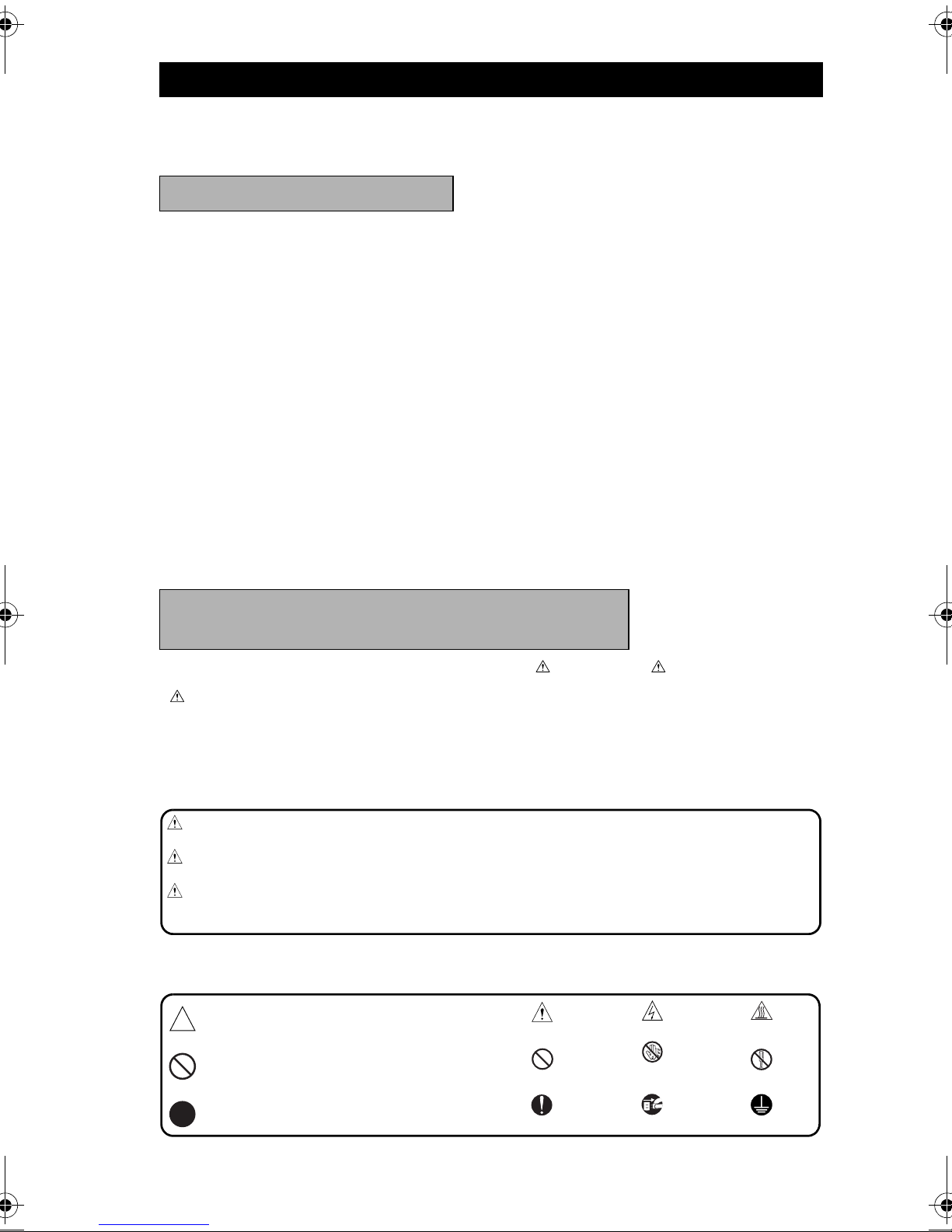
Symbols used for safety and important warning items are defined as follows:
SAFETY AND IMPORTANT WARNING ITEMS
IMPORTANT NOTICE
DESCRIPTION ITEMS FOR DANGER,
WARNING AND CAUTION
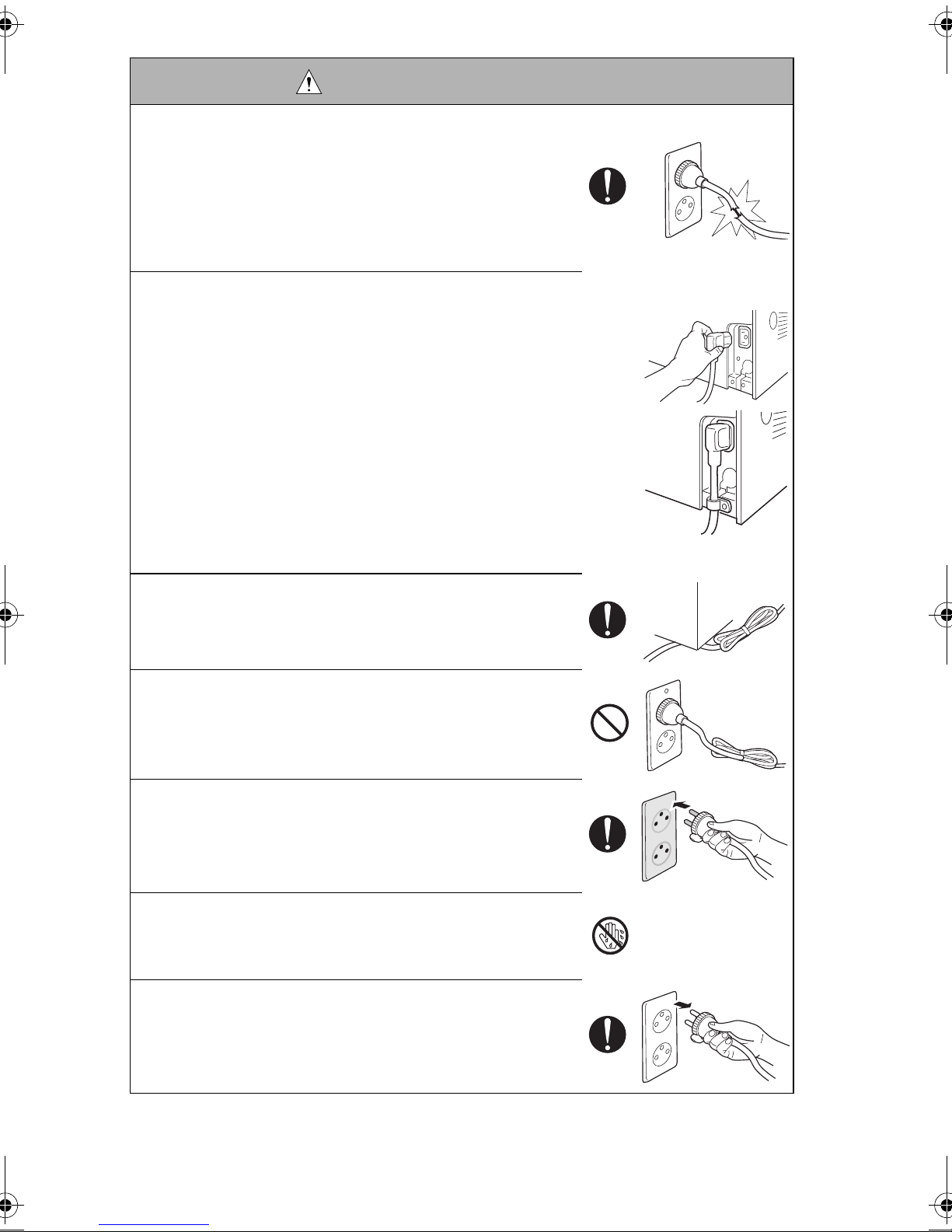
DANGER : Action having a high possibility of suffering death or serious injury
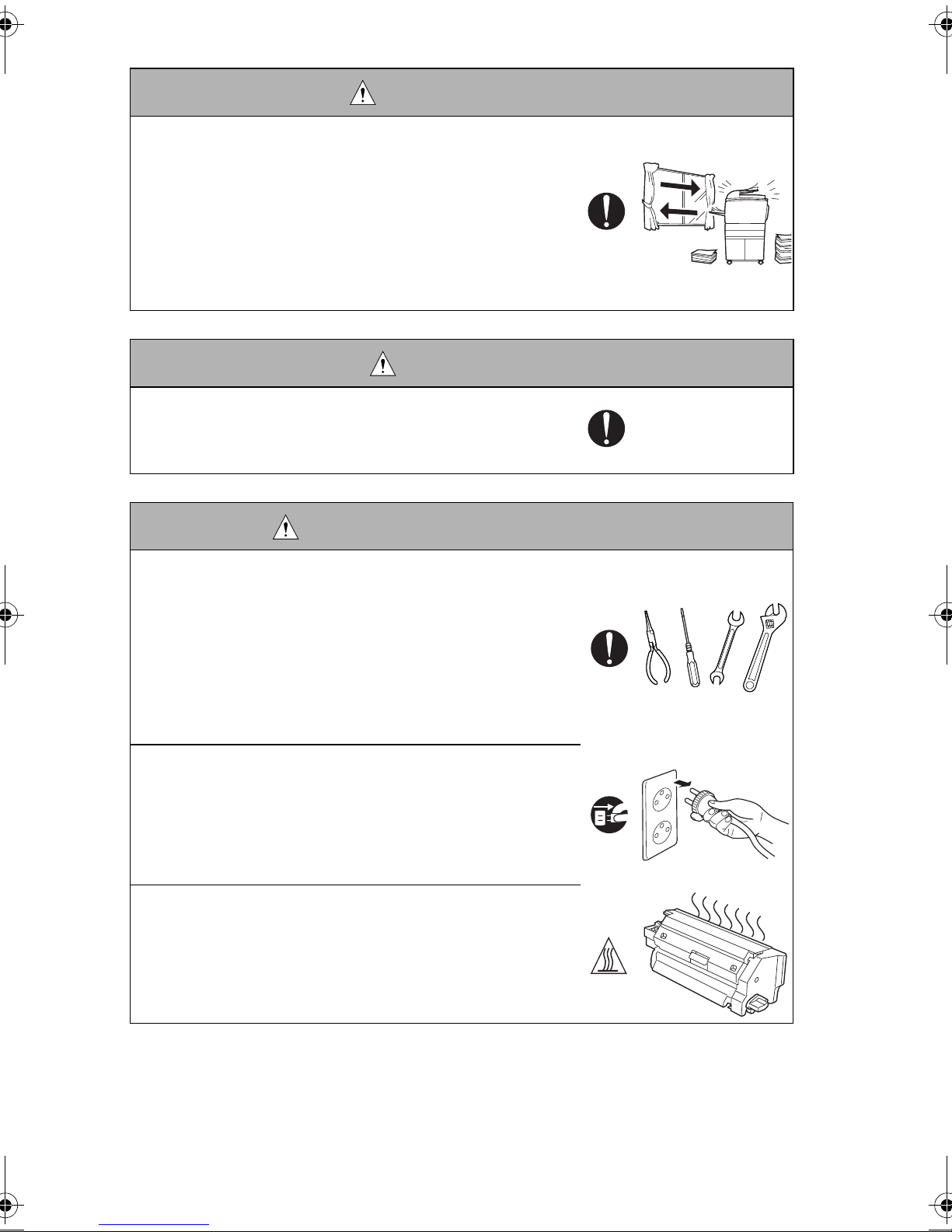
WARNING : Action having a possibility of suffering death or serious injury
CAUTION : Action having a possibility of suffering a slight wound, medium
trouble, and property damage
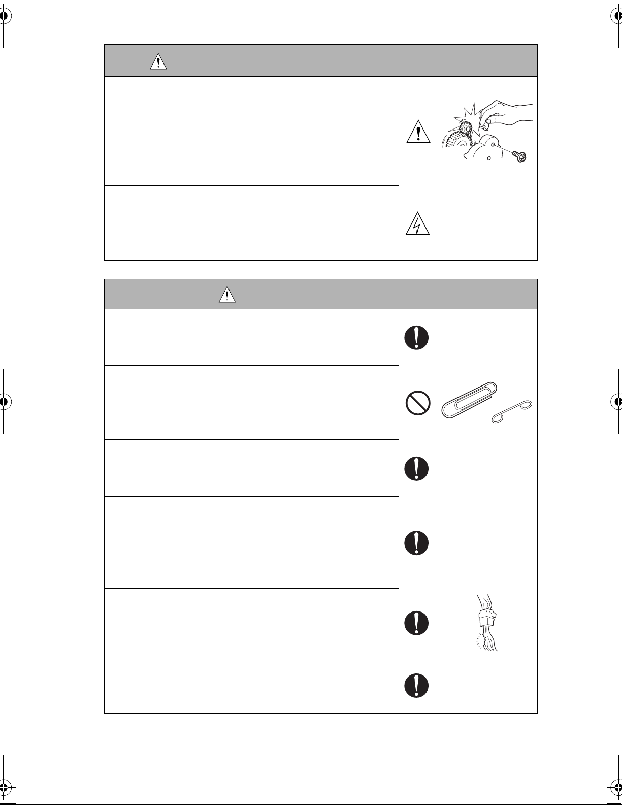
:Precaution when servicing the product. General precaution Electric hazard High temperature
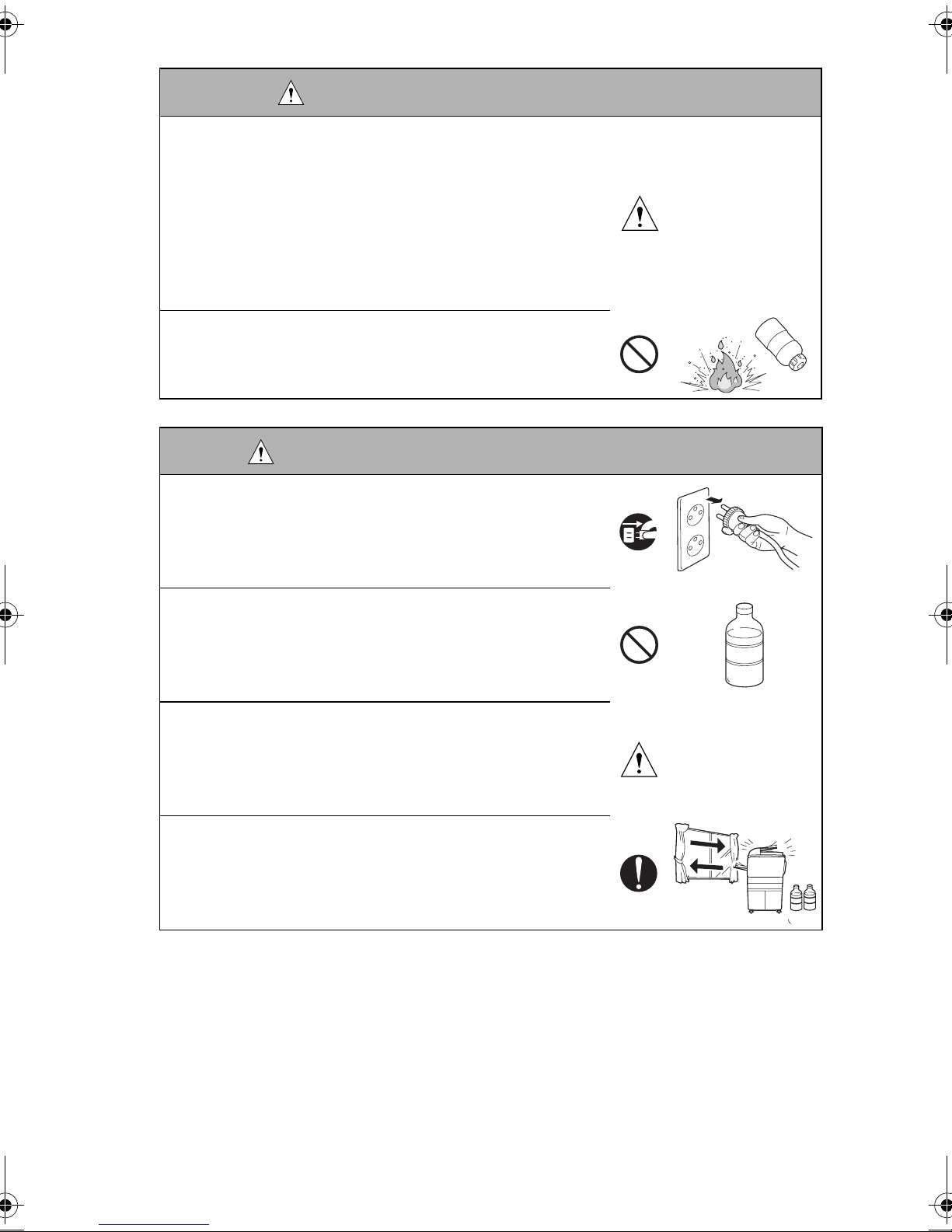
:Prohibition when servicing the product. General prohibition Do not touch
with wet hand Do not disassemble
:Direction when servicing the product.
General instruction Unplug Ground/ Earth
safe_e-1.fm Page 1 Thursday, March 3, 2005 7:29 PM

P-2
1. MODIFICATIONS NOT AUTHORIZED BY
NEC UNIFIED SOLUTIONS, INC.
NEC brand products are renowned for their high reliability. This reliability is achieved
through high-quality design and a solid service network.
Product design is a highly complicated and delicate process where numerous mechanical,
physical, and electrical aspects have to be taken into consideration, with the aim of arriving
at proper tolerances and safety factors. For this reason, unauthorized modifications involve
a high risk of degradation in performance and safety. Such modifications are therefore
strictly prohibited. the points listed below are not exhaustive, but they illustrate the reason-
ing behind this policy.
SAFETY WARNINGS
DANGER: PROHIBITED ACTIONS
• Using any cables or power cord not specified by NEC.
• Using any fuse or thermostat not specified by NEC. Safety
will not be assured, leading to a risk of fire and injury.
• Disabling fuse functions or bridging fuse terminals with
wire, metal clips, solder or similar object.
• Disabling relay functions (such as wedging paper between
relay contacts)
• Disabling safety functions (interlocks, safety circuits, etc.)
Safety will not be assured, leading to a risk of fire and
injury.
• Making any modification to the product unless instructed
by NEC.
safe_e-1.fm Page 2 Thursday, March 3, 2005 7:29 PM

P-3
2. CHECKPOINTS WHEN PERFORMING ON-SITE SER-
VICE
NEC brand products are extensively tested before shipping, to ensure that all applicable
safety standards are met, in order to protect the customer and customer engineer (hereaf-
ter called the CE) from the risk of injury. However, in daily use, any electrical equipment
may be subject to parts wear and eventual failure. In order to maintain safety and reliability,
the CE must perform regular safety checks.
1. Power Supply
• Using parts not specified by NEC.
WARNING: Wall Outlet
• Check that mains voltage is as specified. Plug the power
cord into the dedicated wall outlet with a capacity greater
than the maximum power consumption.
If excessive current flows in the wall outlet, fire may
result.
• If two or more power cords can be plugged into the wall
outlet, the total load must not exceed the rating of the wall
outlet.
If excessive current flows in the wall outlet, fire may
result.
WARNING: Power Plug and Cord
• Make sure the power cord is plugged in the wall outlet
securely.
Contact problems may lead to increased resistance,
overheating, and the risk of fire.
DANGER: PROHIBITED ACTIONS
safe_e-1.fm Page 3 Thursday, March 3, 2005 7:29 PM

P-4
• Check whether the power cord is damaged. Check
whether the sheath is damaged.
If the power plug, cord, or sheath is damaged, replace
with a new power cord (with plug and connector on each
end) specified by NEC. Using the damaged power cord
may result in fire or electric shock.
• When using the power cord (inlet type) that came with this
product, be sure to observe the following precautions:
a. Make sure the connector is securely inserted in the inlet
on the rear panel of the product.
Secure the cord with a fixture properly.
b. If the power cord or sheath is damaged, replace with a
new power cord (with plugs on both ends) specified by
NEC.
If the power cord (inlet type) is not connected to the
product securely, a contact problem may lead to
increased resistance, overheating, and risk of fire.
• Check whether the power cord is not stepped on or
pinched by a table and so on.
Overheating may occur there, leading to a risk of fire.
• Do not bundle or tie the power cord.
Overheating may occur there, leading to a risk of fire.
• Check whether dust is collected around the power plug
and wall outlet.
Using the power plug and wall outlet without removing
dust may result in fire.
• Do not insert the power plug into the wall outlet with a wet
hand.
The risk of electric shock exists.
• When unplugging the power cord, grasp the plug, not the
cable.
The cable may be broken, leading to a risk of fire and
electric shock.
WARNING: Power Plug and Cord
safe_e-1.fm Page 4 Thursday, March 3, 2005 7:29 PM

P-5
2. Installation Requirements
WARNING: Wiring
• Never use multi-plug adapters to plug multiple power
cords in the same outlet.
If used, the risk of fire exists.
• When an extension cord is required, use a specified one.
Current that can flow in the extension cord is limited, so
using a too long extension cord may result in fire.
Do not use an extension cable reel with the cable taken
up. Fire may result.
WARNING: Ground connection
• Check whether the product is grounded properly.
If current leakage occurs in an ungrounded product, you
may suffer electric shock while operating the product.
Connect power plug to grounded wall outlet.
WARNING: Prohibited Installation Place
• Do not place the product near flammable materials or vola-
tile materials that may catch fire.
A risk of fire exists.
• Do not place the product in a place exposed to water such
as rain.
A risk of fire and electric shock exists.
WARNING: When not using product for a long time
• When the product is not used over an extended period of
time (holidays, etc.), switch it off and unplug the power
cord.
Dust collected around the power plug and outlet may
cause fire.
safe_e-1.fm Page 5 Thursday, March 3, 2005 7:29 PM

P-6
CAUTION: Ventilation
• The product generates ozone gas during operation, but it
will not be harmful to the human body.
If a bad smell of ozone is present in the following cases,
ventilate the room.
a. When the product is used in a poorly ventilated room
b. When taking a lot of copies
c. When using multiple products at the same time
CAUTION: Fixing
• Be sure to lock the caster stoppers.
In the case of an earthquake and so on, the product may
slide, leading to a injury.
CAUTION: Inspection before Servicing
• Before conducting an inspection, read all relevant docu-
mentation (service manual, technical notices, etc.) and
proceed with the inspection following the prescribed pro-
cedure, using only the prescribed tools. Do not make any
adjustment not described in the documentation.
If the prescribed procedure or tool is not used, the prod-
uct may break and a risk of injury or fire exists.
• Before conducting an inspection, be sure to disconnect the
power plugs from the product and options.
When the power plug is inserted in the wall outlet, some
units are still powered even if the POWER switch is
turned OFF. A risk of electric shock exists.
• The area around the fixing unit is hot.
You may get burnt.
safe_e-1.fm Page 6 Thursday, March 3, 2005 7:29 PM

P-7
WARNING: Work Performed with the product Powered
• Take every care when making adjustments or performing
an operation check with the product powered.
If you make adjustments or perform an operation check
with the external cover detached, you may touch live or
high-voltage parts or you may be caught in moving gears
or the timing belt, leading to a risk of injury.
• Take every care when servicing with the external cover
detached.
High-voltage exists around the drum unit. A risk of elec-
tric shock exists.
WARNING: Safety Checkpoints
• Check the exterior and frame for edges, burrs, and other
damages.
The user or CE may be injured.
• Do not allow any metal parts such as clips, staples, and
screws to fall into the product.
They can short internal circuits and cause electric shock
or fire.
• Check wiring for squeezing and any other damage.
Current can leak, leading to a risk of electric shock or
fire.
• Carefully remove all toner remnants and dust from electri-
cal parts and electrode units such as a charging corona
unit.
Current can leak, leading to a risk of product trouble or
fire.
• Check high-voltage cables and sheaths for any damage.
Current can leak, leading to a risk of electric shock or
fire.
• Check electrode units such as a charging corona unit for
deterioration and sign of leakage.
Current can leak, leading to a risk of trouble or fire.
safe_e-1.fm Page 7 Thursday, March 3, 2005 7:29 PM

P-8
• Before disassembling or adjusting the write unit (P/H unit)
incorporating a laser, make sure that the power cord has
been disconnected.
The laser light can enter your eye, leading to a risk of
loss of eyesight.
• Do not remove the cover of the write unit. Do not supply
power with the write unit shifted from the specified mount-
ing position.
The laser light can enter your eye, leading to a risk of
loss of eyesight.
• When replacing a lithium battery, replace it with a new lith-
ium battery specified in the Parts Guide Manual. Dispose
of the used lithium battery using the method specified by
local authority.
Improper replacement can cause explosion.
• After replacing a part to which AC voltage is applied (e.g.,
optical lamp and fixing lamp), be sure to check the installa-
tion state.
A risk of fire exists.
• Check the interlock switch and actuator for loosening and
check whether the interlock functions properly.
If the interlock does not function, you may receive an
electric shock or be injured when you insert your hand in
the product (e.g., for clearing paper jam).
• Make sure the wiring cannot come into contact with sharp
edges, burrs, or other pointed parts.
Current can leak, leading to a risk of electric shock or
fire.
• Make sure that all screws, components, wiring, connec-
tors, etc. that were removed for safety check and mainte-
nance have been reinstalled in the original location. (Pay
special attention to forgotten connectors, pinched cables,
forgotten screws, etc.)
A risk of product trouble, electric shock, and fire exists.
WARNING: Safety Checkpoints
safe_e-1.fm Page 8 Thursday, March 3, 2005 7:29 PM

P-9
WARNING: HANDLING OF CONSUMABLE
• Toner and developer are not harmful substances, but care
must be taken not to breathe excessive amounts or let the
substances come into contact with eyes, etc. It may be
stimulative.
If the substances get in the eye, rinse with plenty of water
immediately. When symptoms are noticeable, consult a
physician.
• Never throw the used cartridge and toner into fire.
You may be burned due to dust explosion.
CAUTION: HANDLING OF SERVICE MATERIALS
• Unplug the power cord from the wall outlet.
Drum cleaner (isopropyl alcohol) and roller cleaner (ace-
tone-based) are highly flammable and must be handled
with care. A risk of fire exists.
• Do not replace the cover or turn the product ON before
any solvent remnants on the cleaned parts have fully
evaporated.
A risk of fire exists.
• Use only a small amount of cleaner at a time and take care
not to spill any liquid. If this happens, immediately wipe it
off.
A risk of fire exists.
• When using any solvent, ventilate the room well.
Breathing large quantities of organic solvents can lead to
discomfort.
safe_e-1.fm Page 9 Thursday, March 3, 2005 7:29 PM

P-10
3. MEASURES TO TAKE IN CASE OF AN ACCIDENT
1. If an accident has occurred, the distributor who has been notified first must immediately
take emergency measures to provide relief to affected persons and to prevent further
damage.
2. If a report of a serious accident has been received from a customer, an on-site evalua-
tion must be carried out quickly and NEC must be notified.
3. To determine the cause of the accident, conditions and materials must be recorded
through direct on-site checks, in accordance with instructions issued by NEC.
4. CONCLUSION
1. Safety of users and customer engineers depends highly on accurate maintenance and
administration. Therefore, safety can be maintained by the appropriate daily service
work conducted by the customer engineer.
2. When performing service, each product on the site must be tested for safety. The cus-
tomer engineer must verify the safety of parts and ensure appropriate management of
the equipment.
safe_e-1.fm Page 10 Thursday, March 3, 2005 7:29 PM

P-11
5. Used Batteries Precautions
ALL Areas
CAUTION
Danger of explosion if battery is incorrectly replaced.
Replace only with the same or equivalent type recommended by the manufacturer.
Dispose of used batteries according to the manufacturer’s instructions.
Germany
VORSICHT!
Explosionsgefahr bei unsachgemäßem Austausch der Batterie.
Ersatz nur durch denselben oder einen vom Hersteller empfohlenen gleichwertigen Typ.
Entsorgung gebrauchter Batterien nach Angaben des Herstellers.
France
ATTENTION
Il y a danger d’explosion s’il y a remplacement incorrect de la batterie.
Remplacer uniquement avec une batterie du même type ou d’un type équivalent recom-
mandé par le constructeur. Mettre au rebut les batteries usagées conformément aux
instructions du fabricant.
Denmark
ADVARSEL!
Lithiumbatteri - Eksplosionsfare ved fejlagtig håndtering.
Udskiftning må kun ske med batteri af samme fabrikat og type. Levér det brugte batteri til-
bage til leverandøren.
Finland, Sweden
VAROlTUS
Paristo voi räjähtää, jos se on virheellisesti asennettu.
Vaihda paristo ainoastaan laitevalmistajan suosittelemaan tyyppiin. Hävitä käytetty paristo
valmistajan ohjeiden mukaisesti.
VARNING
Explosionsfara vid felaktigt batteribyte.
Använd samma batterityp eller en ekvivalent typ som rekommenderas av apparat-
tillverkaren. Kassera använt batteri enligt fabrikantens instruktion.
Norway
ADVARSEL
Eksplosjonsfare ved feilaktig skifte av batteri.
Benytt samme batteritype eller en tilsvarende type anbefalt av apparatfabrikanten. Brukte
batterier kasseres i henhold til fabrikantens instruksjoner.
safe_e-1.fm Page 11 Thursday, March 3, 2005 7:29 PM

INDEX (Field Service)
MAINTENANCE
GENERAL
CONTROL PANEL/SERVICE
MODE DESCRIPTIONS
DIS/REASSEMBLY,
ADJUSTMENT
TROUBLESHOOTING

i
CONTENTS
GENERAL
1. SPECIFICATIONS ........................................................................................... G-1
1-1. Main Uint .................................................................................................. G-1
1-2. GDI Printer Function ................................................................................ G-3
1-3. FAX Function ............................................................................................ G-3
1-4. Network Function (NEFAX 691 only) ....................................................... G-5
2. PRECAUTIONS FOR INSTALLATION ............................................................ G-6
2-1. To Ensure THIS MACHINE is Used in an Optimum Condition ................ G-6
2-2. To Ensure the printer is Used in an Optimum Condition .......................... G-6
3. PRECAUTIONS FOR USE .............................................................................. G-7
3-1. To Ensure the Printer is Used in an Optimum Condition ......................... G-7
3-2. Operating Environment ............................................................................ G-7
3-3. Power Requirements ................................................................................ G-7
4. HANDLING OF THE CONSUMABLES ............................................................ G-8
5. MISCELLANEOUS PRECAUTIONS ................................................................ G-8
6. PARTS IDENTIFICATION ................................................................................ G-9
MAINTENANCE
1. MAINTENANCE SCHEDULE .......................................................................... E-1
1-1. Guidelines for Life Specifications Values by Unit ..................................... E-2
(1) Life Specifications Values ................................................................ E-2
2. REPLACEMENT/CLEANING OF PARTS ........................................................ E-3
(1) Cleaning of the Paper Take-Up Roller ............................................. E-3
(2) Replacement of the Paper Take-Up Roller ...................................... E-3
(3) Replacement of the Image Transfer Roller ...................................... E-4
3. REPLACEMENT OF UNITS ............................................................................ E-5
(1) Replacement of the Toner Cartridge ................................................ E-5
(2) Replacement of the Drum Cartridge ................................................ E-7
(3) Replacement of the Fusing Unit ....................................................... E-7
4. REPLACEMENT OF DOCUMENT FEEDER ................................................... E-10
(1) Cleaning of the Paper Take-Up Roller .............................................. E-10
(2) Replacement of the Paper Take-Up Roller ....................................... E-10
(3) Cleaning of the Pick-Up Roller.......................................................... E-11
(4) Removal of the Pick-Up Roller.......................................................... E-12
(5) Cleaning of the Registration Rollers ................................................. E-12
(6) Cleaning of the Transport Roller ....................................................... E-12
(7) Cleaning of the Exit Roller ................................................................ E-12
(8) Cleaning of the Paper Separator Pad ............................................... E-13
(9) Removal of the Paper Separator Pad ............................................... E-13
(10) Cleaning of the CIS and Shading roller............................................. E-14
(11) Removal of the CIS........................................................................... E-15
DIS/REASSEMBLY,ADJUSTMENT
1. SAFETY INFORMATION ................................................................................. D-1
1-1. Laser Safety ............................................................................................. D-1
1-2. Internal Laser Radiation ........................................................................... D-1
1-3. Laser Safety Label ................................................................................... D-4

ii
1-4. Laser Safety Label .................................................................................. D-4
1-5. Precautions for Handling the Laser Equipment ....................................... D-5
2. PRECAUTIONS FOR DISASSEMBLY/ADJUSTMENTS ................................ D-6
2-1. Parts That Must Not be Touched ............................................................ D-6
(1) Red Painted Screws ........................................................................ D-6
(2) Variable resistors on board ............................................................. D-6
(3) Other Screws not Marked with Red Paint ....................................... D-6
3. DISASSEMBLY/REASSEMBLY ...................................................................... D-7
3-1. Identification of Exterior Parts and Removal Procedures for Them ........ D-8
3-2. Name/Removal of External Parts ............................................................ D-8
3-3. Removal of the Circuit Boards and Other Eletrical Components...................D-9
3-4. Removal of Ciruit Boards ........................................................................ D-10
(1) Removal of the Network Interface Card Board................................. D-11
(2) Removal of the Network Control Unit Board D-11
(3) Removal of the Controller/Mechanical Control Board ..................... D-12
(4) Removal of the Control Panel ......................................................... D-12
(5) Removal of the Interface Board ....................................................... D-13
(6) Removal of the Plate NIC Board .................................................... D-14
(7) Removal of the Power Unit ............................................................. D-15
(8) Removal of the High Voltage Unit ................................................... D-16
3-5. Removal of Units ..................................................................................... D-17
(1) Removal of the ADF Unit ................................................................ D-17
(2) Removal of the PH Unit ................................................................... D-17
(3) Removal of the Automatic Document Feeder unit............................ D-21
(4) Removal of the Automatic Document Feeder Control...................... D-22
(5) Removal of the AFEIF Board ........................................................... D-22
(6) Removal of the Automatic Document Feeder Main Motor ............... D-23
3-6. Disassembly of the Main Drive Section ................................................... D-24
(1) Removal of the Main Motor ............................................................. D-24
(2) Removal of the Paper Empty Sensors ............................................ D-24
(3) Removal of the Paper Take-Up Solenoid ........................................ D-25
(4) Removal of the Paper Take-Up Clutch Gear ................................... D-27
(5) Removal of the Torque Limiter ........................................................ D-28
(6) Disassembly of the Fusing Unit ....................................................... D-29
4. ADJUSTMENTS .............................................................................................. D-31
4-1. Electrical/Image Adjustment .................................................................... D-31
(1) Accessing the Service Mode ........................................................... D-31
(2) Accessing the “ADJUST” Menu ....................................................... D-31
(3) Printing a Test Pattern .................................................................... D-31
(4) Margin Adjustment (Leading Edge/Trailing Edge/Both Sides) ........ D-32
(5) Printer’s Main Scanning Registration Adjustment ........................... D-33
(6) Printer’s Sub-Scanning Registration Adjustment ............................ D-34
(7) Leading Edge Tilt Adjustment .......................................................... D-35
(8) Automatic Document Feeder Sub-Scanning Zoom Ratio
Adjustment ..................................................................................... D-36
(9) Automatic Document Feeder Main-Scanning Registration
Adjustment ..................................................................................... D-37

iii
(10) Automatic Document Feeder Sub-Scanning Registration
Adjustment ....................................................................................... D-38
4-2. ADJUSTMENT OF JUMPER SWITCHES ON NCU BOARD ................... D-39
5. MISCELLANEOUS ........................................................................................... D-40
5-1. Updating the Firmware ............................................................................. D-40
(1) Installing the GDI Printer Driver/
TWAIN Driver Using Plug and Play ..................................................D-40
(2) Procedure for Upgrading the Firmware
(Engine firmware/ FAX firmware) ..................................................... D-42
5-2. Procedure for Upgrading the Firmware
(NIC Firmware NEFAX 691 only) ............................................................. D-45
5-3. Remedy for a Failed Updating of the Firmware ....................................... D-47
5-4. Moving the EEPROM ............................................................................... D-49
CONTROL PANEL/SERVICE MODE DESCRIPTIONS
1. CONTROL PANEL DESCRIPTIONS ............................................................... S-1
1-1. Names of Control Panel Parts and Their Functions ................................ S-1
2. FUNCTIONS OF SWITCHES AND PARTS ON PWBs ................................... S-4
2-1.. Circuit Board Locations NEFAX 671......................................................... S-4
2-2.. Circuit Board Locations NEFAX 691......................................................... S-4
2-3. PWB-P (Controller/Mechanical Control Board) ........................................ S-5
2-4. PWB-IF (Interface Board) ......................................................................... S-5
2-5. NCU (Network Control Unit Board) ......................................................... S-6
2-6. NIC (Network Interface Card Board) ........................................................ S-6
2-7. NIC-IF (Plate NIC Board) ........................................................................ S-6
(1)LED status display list ......................................................................... S-7
2-8. PWB-A ADF Board) ................................................................................ S-7
3. STATUS MODE ............................................................................................... S-8
3-1. Status Mode Function Tree ...................................................................... S-8
3-2. Status Mode Setting Procedure ............................................................... S-9
(1) Total Page ........................................................................................ S-10
(2) TX/ RX Result ................................................................................. S-10
(3) Print Report ..................................................................................... S-11
4. UTILITY MODE ) .............................................................................................. S-18
4-1. Utility Mode Function Tree (Outline) ........................................................ S-18
4-2. Utility Mode Function Tree (Details) ......................................................... S-19
4-3. Utility Mode Setting Procedure ................................................................. S-22
(1) Machine Setting ............................................................................... S-22
(2) Paper source setting ........................................................................ S-24
(3) Admin. management ........................................................................ S-25
(4) Copy setting ..................................................................................... S-27
(5) FAX registration ............................................................................... S-27
(6) TX operation .................................................................................... S-30
(7) RX operation .................................................................................... S-33
(8) Comm. setting .................................................................................. S-41
(9) Reporting ......................................................................................... S-44
(10) Initial user data ................................................................................. S-45

iv
(11) Network setting ................................................................................ S-46
(12) E-mail setting 1 ................................................................................ S-48
(13) E-mail setting 2 ................................................................................ S-50
(14) Scan setting ..................................................................................... S-52
5. SERVICE MODE ............................................................................................. S-54
5-1. Service Mode Function Tree(Outline) ...................................................... S-54
5-2. Service Mode Function Tree(Details) ...................................................... S-55
5-3. Service Mode Setting Procedure ............................................................. S-58
(1) <Procedure> .................................................................................... S-58
(2) <Exiting Procedure> ........................................................................ S-58
(3) <Changing the Settings for Service Mode Functions> .................... S-58
5-4. Service’s Choice Functions ..................................................................... S-59
(1) Marketing Area ................................................................................ S-60
(2) Shipment Destination ...................................................................... S-61
(3) Leading Edge Erase ........................................................................ S-62
(4) Trailing Edge Erase ......................................................................... S-62
(5) Vertical Edge Erase ......................................................................... S-63
(6) FLS Paper Size ............................................................................... S-63
(7) TX Speed ........................................................................................ S-63
(8) RX Speed ........................................................................................ S-63
(9) TX Level .......................................................................................... S-64
(10) RX Level .......................................................................................... S-64
(11) DTMF Level ..................................................................................... S-64
(12) CNG Level ....................................................................................... S-64
(13) CED Level ....................................................................................... S-65
(14) ECM Mode ...................................................................................... S-65
(15) Coding Scheme ............................................................................... S-65
(16) Toner Empty Report ........................................................................ S-66
(17) Protocol Report ............................................................................... S-67
(18) GDI Time out ................................................................................... S-67
(19) Toner Empty Stop ........................................................................... S-68
(20) Pre-rotation ...................................................................................... S-68
(21) Fuser Temp Ad. ............................................................................... S-68
5-5. Adjust Function ........................................................................................ S-69
(1) Adjust ............................................................................................ S-69
5-6. Counter Function ..................................................................................... S-70
(1) Counter ............................................................................................ S-70
5-7. Display Function ...................................................................................... S-73
(1) Display ............................................................................................ S-73
5-8. Soft Switch Function ................................................................................ S-74
5-9. Reporting ................................................................................................. S-75
(1) Service Data List ............................................................................. S-75
(2) Error Code List ................................................................................ S-78
(3) T.30 Protocol List ............................................................................ S-79
5-10.Admin. Registration (Administrator number registration) ........................ S-80
5-11.Fixed zoom change ................................................................................. S-81
(1) <Metric> .......................................................................................... S-81

v
(2) <Inch> ............................................................................................. S-81
5-12.Clear Data ................................................................................................ S-82
(1) DRAM clear ...................................................................................... S-82
(2) SRAM clear ...................................................................................... S-83
(3) Memory clear ................................................................................... S-85
(4) Total clear ........................................................................................ S-87
(5) Total counter ..................................................................................... S-87
(6) PM counter (clear) ........................................................................... S-87
(7) I/C counter (clear) ............................................................................ S-87
(8) Application counter (clear) ............................................................... S-87
(9) Scan counter (clear) ......................................................................... S-87
6. Soft Switch Set ................................................................................................ S-88
6-1. Description ............................................................................................... S-88
6-2. Default setting .......................................................................................... S-89
(1) Country for each Marketing area ..................................................... S-89
6-3. Default soft switch setting for each market area 1 ................................... S-90
6-4. Default soft switch setting for each market area 2 ................................... S-92
6-5. Default soft switch setting for each market area 3 ................................... S-94
6-6. Default soft switch setting for each market area 4 ................................... S-96
6-7. Default soft switch setting for each market area 5 ................................... S-98
6-8. Default soft switch setting for each market area 6 ................................... S-100
6-9. Default soft switch setting for each market area 7 ................................... S-102
6-10.Default soft switch setting for each market area 8 ................................... S-104
6-11.Soft Switch List ........................................................................................ S-106
6-12.Soft Switch definition ................................................................................ S-110
(1) SOFT SWITCH: #01 ........................................................................ S-110
(2) SOFT SWITCH: #02 ........................................................................ S-111
(3) SOFT SWITCH: #03 ........................................................................ S-112
(4) SOFT SWITCH: #04 ........................................................................ S-113
(5) SOFT SWITCH: #05 ........................................................................ S-114
(6) SOFT SWITCH: #06 ........................................................................ S-115
(7) SOFT SWITCH: #07 ........................................................................ S-115
(8) SOFT SWITCH: #08 ........................................................................ S-116
(9) SOFT SWITCH: #09 ........................................................................ S-117
(10) SOFT SWITCH: #10 ........................................................................ S-118
(11) SOFT SWITCH: #11 ........................................................................ S-119
(12) SOFT SWITCH: #12 ........................................................................ S-119
(13) SOFT SWITCH: #13 ........................................................................ S-120
(14) SOFT SWITCH: #14 ........................................................................ S-121
(15) SOFT SWITCH: #15 ........................................................................ S-121
(16) SOFT SWITCH: #16 ........................................................................ S-122
(17) SOFT SWITCH: #17 ........................................................................ S-122
(18) SOFT SWITCH: #18 ........................................................................ S-123
(19) SOFT SWITCH: #19 ........................................................................ S-124
(20) SOFT SWITCH: #20 ........................................................................ S-125
(21) SOFT SWITCH: #21 ........................................................................ S-126
(22) SOFT SWITCH: #22 ........................................................................ S-127

vi
(23) SOFT SWITCH: #23 ........................................................................ S-127
(24) SOFT SWITCH: #24 ........................................................................ S-128
(25) SOFT SWITCH: #25 ........................................................................ S-128
(26) SOFT SWITCH: #26 ........................................................................ S-129
(27) SOFT SWITCH: #27 ........................................................................ S-130
(28) SOFT SWITCH: #28 ........................................................................ S-131
(29) SOFT SWITCH: #29 ........................................................................ S-132
(30) SOFT SWITCH: #30 ........................................................................ S-133
(31) SOFT SWITCH: #31 ........................................................................ S-134
(32) SOFT SWITCH: #32 ........................................................................ S-134
(33) SOFT SWITCH: #33 ........................................................................ S-135
(34) SOFT SWITCH: #34 ........................................................................ S-135
(35) SOFT SWITCH: #35 ........................................................................ S-136
(36) SOFT SWITCH: #36 ........................................................................ S-137
(37) SOFT SWITCH: #37 ........................................................................ S-138
(38) SOFT SWITCH: #38 ........................................................................ S-139
(39) SOFT SWITCH: #39 ........................................................................ S-139
(40) SOFT SWITCH: #40 ........................................................................ S-140
(41) SOFT SWITCH: #41 ........................................................................ S-141
(42) SOFT SWITCH: #42 ........................................................................ S-142
(43) SOFT SWITCH: #43 ........................................................................ S-142
(44) SOFT SWITCH: #44 ........................................................................ S-142
(45) SOFT SWITCH: #45 ........................................................................ S-143
(46) SOFT SWITCH: #46 ........................................................................ S-144
(47) SOFT SWITCH: #47 ........................................................................ S-144
(48) SOFT SWITCH: #48 ........................................................................ S-145
(49) SOFT SWITCH: #49 ........................................................................ S-146
(50) SOFT SWITCH: #50 ........................................................................ S-146
(51) SOFT SWITCH: #51 ........................................................................ S-147
(52) SOFT SWITCH: #52 ........................................................................ S-147
(53) SOFT SWITCH: #53 ........................................................................ S-148
(54) SOFT SWITCH: #54 ........................................................................ S-148
(55) SOFT SWITCH: #55 ........................................................................ S-149
(56) SOFT SWITCH: #56 ........................................................................ S-149
(57) SOFT SWITCH: #57 ........................................................................ S-149
(58) SOFT SWITCH: #58 ........................................................................ S-150
(59) SOFT SWITCH: #59 Part 1 ............................................................. S-151
(60) SOFT SWITCH: #59 Part 2 ............................................................. S-152
(61) SOFT SWITCH: #59 Part 3 ............................................................. S-153
(62) SOFT SWITCH: #60 ........................................................................ S-154
(63) SOFT SWITCH: #61 ........................................................................ S-154
(64) SOFT SWITCH: #62 ........................................................................ S-155
(65) SOFT SWITCH: #63 ........................................................................ S-155
(66) SOFT SWITCH: #64 ........................................................................ S-156
7. Fax Protocols ................................................................................................... S-157
7-1. G3 ECM (G3 Error Correction Mode) ...................................................... S-157
7-2. Line Control ............................................................................................. S-158

vii
(1) Procedure of G3 mode communication ........................................... S-158
7-3. Table of reference code ........................................................................... S-159
7-4. How to analyze the T30 protocol monitor ................................................. S-160
TROUBLESHOOTING
1. INTRODUCTION .............................................................................................. T-1
1-1. Electric Components Check Procedures ................................................. T-1
(1) Sensors ............................................................................................ T-1
(2) Switches ........................................................................................... T-2
(3) Solenoids ......................................................................................... T-2
(4) Motors ............................................................................................. T-3
(5) Clutches ........................................................................................... T-4
1-2. Overall Control Configuration ................................................................... T-5
2. PAPER MISFEED ............................................................................................ T-6
2-1. Initial Check Items .................................................................................... T-6
2-2. ADF Unit Initial Check Items .................................................................... T-6
2-3. Paper Misfeed Displays ........................................................................... T-7
2-4. ADF Unit Paper Misfeed Displays ............................................................ T-8
2-5. Locations of Misfeed Detection Sensors .................................................. T-9
2-6. ADF Unit Locations of Misfeed Detection Sensors .................................. T-10
2-7. Misfeed Detection Timing and Troubleshooting Procedures ................... T-11
(1) Paper Take-Up/Transport Misfeed ................................................... T-11
(2) Fusing/Exit Misfeed .......................................................................... T-12
3. PAPER MISFEED(Document Feeder Section)................................................. T-13
(1) The Original Timing ................................................................................... T-13
4. MALFUNCTIONS/WARNING .......................................................................... T-14
4-1. List of Malfunctions .................................................................................. T-14
4-2. Malfunction Detection Timing and Troubleshooting Procedures .............. T-16
(1) C0045: Fuser fan motor error .......................................................... T-16
(2) C0210: H.V. abnormal ..................................................................... T-17
(3) C0500: Fuser warm up error ............................................................ T-18
(4) C0510: Fuser temperature low ........................................................ T-19
(5) C0520: Fuser overheat .................................................................... T-20
(6) C1200: ASIC memory abnormal ...................................................... T-21
(7) C1300: Polygon mirror motor error .................................................. T-21
(8) C133B: Communication with option error ........................................ T-22
(9) C133C: Modem error ....................................................................... T-22
(10) C133D: ROM checksum error .......................................................... T-22
(11) C13F0: Laser error ........................................................................... T-23
(12) C1468: EEPROM error .................................................................... T-23
(13) C14A3: CIS LED malfunction ........................................................... T-24
5. MALFUNCTIONS RELATED TO POWER SUPPLY ....................................... T-25
5-1. Power is not Turned ON. .......................................................................... T-25
6. IMAGE QUALITY PROBLEMS ........................................................................ T-26
6-1. Troubleshooting Image Quality Problems ................................................ T-26
6-2. Initial Checks ............................................................................................ T-26
Other manuals for NEFAX 671
1
This manual suits for next models
1
Table of contents
Other NEC All In One Printer manuals