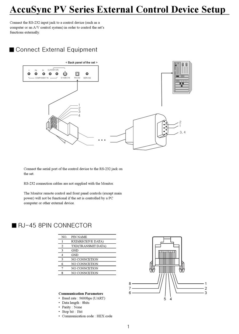
NEC N8181-153 User manual

1
1.
N8181-153 内蔵バッテリーコントロールキット
ユーザーズガイド
はじめに
このたびは、本製品をお買い求めいただき、まことにありがとうございます。
本書は、本製品を正しく安全に設置・使用するための手引きです。本製品をご使用になる前に本書をよく
お読みになり、製品の取り扱いを十分にご理解ください。
必要なときすぐに参照できるよう、お手元に置いておくようにしてください。
ご使用の前に「使用上のご注意」を必ずお読みください。
使用上のご注意 -必ずお読みください -
本製品を安全に正しくご使用になるために必要な情報が記載されています。
本書では、本製品を安全に正しくお使いいただき、お客様への危害や財産への損害を未然に防止するために、
次の絵表示を使用しています。内容をよく理解されてから、本文をお読みください。
本書では、危険の程度を表す用語として、「警告」と「注意」を使用しています。それぞれの用語は次のような
意味を持つものとして定義されています。
危険に対する注意・表示は次の2種類の記号を使用しています。それぞれの記号は次のような意味を持つもの
として定義されています。
注意の喚起
行為の禁止
行為の強制
安全にかかわる表示について
警告
人が死亡する、または重傷を負うおそれがあることを示しています。
注意
火傷や怪我または物的損害を負うおそれがあることを示しています。
注意の喚起
この記号は危険が発生するおそれがあることを表しています。記号の
中の絵表示は危険の内容を図案化したものです。
(例)
(高温注意)
行為の禁止
この記号は行為の禁止を表しています。記号の中や近くの絵表示は禁
止された行為の内容を図案化したものです。
(例)
(分解禁止)
特定しない一般的な注意・警告を示します。
発煙や発火のおそれがあることを示し
ます。
特定しない一般的な禁止を示します。
本体装置の電源プラグをコンセントから抜い
てください。火災や感電のおそれがありま
す。
CBZ-008540-001-04

2
安全にお使いいただくために、次に示す注意事項をお守りください。
警告
万一、煙、異臭、異音などが生じた場合は、ただちに電源をOFFにして電源プラグをコンセント
から抜いてください。その後、お買い求めの販売店または保守サービス会社にご連絡ください。
そのまま使用すると火災の原因となります。
注意
指定した装置以外に取り付けないでください。指定以外の装置にたとえ取り付けることができて
も、取り付けた装置の冷却機能が低下して正常に動作しないばかりか、火災や故障の原因となるお
それがあります。
次に示すような場所や、本体装置のユーザーズガイドで指定している環境条件を超える場所には
設置・保管しないでください。火災や故障の原因となるおそれがあります。
● 薬品や化学物質などを扱う場所
● 直射日光が当たる場所
● 湿気の多い場所
● 不安定な場所
● 急激な温度変化のある場所
● 振動や衝撃のある場所
● 腐食性ガス(二酸化硫黄、硫化水素、二酸化窒素、塩素、アンモニア、オゾンなど)の存在する
環境
● 腐食を促進する成分(塩化ナトリウムや硫黄など)や導電性の金属などが含まれている環境
本製品を正しく動作させるために次に示す注意事項をお守りください。これらの注意を無視した取り扱いを
すると故障の原因になります。
● 本製品を重ね置きしないでください。
● 保管や取り付け・取り外しの際に固いものにぶつけないでください。
● 梱包状態でも落下させないでください。損傷するおそれがあります。
<本書の記号について>
本書の中には次の記号を使用しています。記号は次のような意味をもつものとして定義されています。
ハードウェアの取り扱い、ソフトウェアの操作などにおいて、確認しておかなければならない
ことについて示しています。
本製品を第三者に譲渡(または売却)するときは、必ず本書を含め全ての添付品を一緒にお渡しください。
本製品の廃棄については各自治体の廃棄ルールに従ってください。詳しくは、各自治体へお問い合わせ
ください。
安全上のご注意
取り扱い上のご注意 -本製品を正しく動作させるために -
第三者への譲渡について
廃棄について

3
1.構成品
構成品を確認してください。
項番
品名
数量
概要
1
コントロールキット
1
-
2
バッテリーホルダーブラケット
1
-
3
LED ケーブル
1
-
4
平ネジ
2
-
5
皿ネジ
2
-
6
ケーブルタイ
1
-
7
デバイス用トレー
1
-
8
ユーザーズガイド
1
本書
9
保証書
1
※
※単品出荷時のみ添付されます。工場組み込み出荷時、保証内容は本体装置保証書に
準拠するため、個別保証書は添付されません。
デバイス用トレーは本体装置の3.5型デバイスベイ(2)に標準で取り付けられてい
るものと、本製品の付属品の2つがあります(同じ形状のものです)。
バックアップ装置を既に取り付けている場合、バッテリーの取り付けは本製品に
付属のデバイス用トレーを使用します。バックアップ装置をまだ取り付けていな
い場合は、バッテリーの取り付けは本体装置のデバイス用トレーを使用し、本製
品に付属のものは大切に保管しておいてください。
8. ユーザーズガイド
6. ケーブルタイ
1. コントロールキット
7. デバイス用トレー
3. LED ケーブル
2. バッテリーホルダーブラケット
5. 皿ネジ
9. 保証書
4. 平ネジ

4
2.装置への取り付け
次の手順にて装置に取り付けを行ってください。
1. 本体装置のユーザーズガイドを参照して、サイドカバーとフロントベゼルを取り外します。
2. ブランクカバーを取り外し、3.5型拡張ベイ(2)の中にあるデバイス用トレーの上のタブを押しながら
(①)デバイス用トレーを本体装置から取り外します(②)。取り外したデバイス用トレーは、この後の手
順4でLEDケーブルを取り付けます。
3. 次の手順で、電源ユニットの前方へコントロールキットを搭載します。
3-1. 図のようにコントロールキット本体を挿入し、先端が3.5型拡張ベイ(2)に突き当たる
まで前方へスライドさせる。
3-2. 付属の皿ネジ(1本)と平ネジ(1本)で固定します。
皿ネジ
平ネジ
電源ユニット
コントロールキット
3.5型拡張ベイ(2)
既に3.5型拡張ベイ(2)にバックアップ装置が
搭載されている場合は、3.5型拡張ベイ(1)に移
動してください。
バックアップ装置の3.5型デバイスベイ(1)へ
の取り付け方法については、本体装置のユーザ
ーズガイドに記載の「増設用2.5型HDDケージ」
と「バックアップ装置」の取り付け手順を参照
してください。
デバイス用トレー
(3.5型拡張ベイ(2))
3.5型拡張ベイ(1)

5
3-3. マザーボード上の電源コネクタから電源ケーブル2本を取り外します。
3-4. コントロールキットのI2Cケーブルをマザーボード上のI2Cコネクタに接続します。
3-5. 手順3-3で取り外した電源ケーブル(2本)をコントロールキットのコネクタに接続します
(図の丸部分)
装置背面
装置前面
マザーボード
マザーボード上の電源コネクタの位置
は、手順7-4の図を参照してください。
I2Cケーブル
マザーボード上のI2Cコネクタの位置は、
手順7-4の図を参照してください。
I2Cコネクタ
コントロールキット
P2
P1

6
3-6. コントロールキットからの電源ケーブル(2本)を手順3-3で外したマザーボード上のコネクタ
へ接続します。
4. 手順2.で取り外したデバイス用トレーへ付属のLEDケーブルを取り付けます。
4-1. デバイス用トレーの右端にLEDケーブルのブラケット部を取り付けます。
4-2. 付属の平ネジ(1本)で固定します。
4-3. 図の位置にケーブルタイでLEDケーブルをデバイス用トレーに固定します。
(ケーブルタイはデバイス用トレーの側面の2ヶ所の穴を通して固定します)
マザーボード上の電源コネクタの位置
は、手順7-4の図を参照してください。
LEDケーブル
ブラケット
平ネジ
バックアップ装置の実装のために、既
に3.5型拡張ベイ(2)にあるデバイス用
トレーが使用されている場合は、本製
品に付属のデバイス用トレーを使用し
てください。

7
5. LEDケーブルを取り付けたデバイス用トレーを3.5型拡張ベイ(2)に戻します。次に、LEDケーブルを
コントロールキットのCN102コネクタに接続します。
6. 次の手順に従ってN8181-152内蔵バッテリーモジュールを取り付けます。
6-1.バッテリーホルダーブラケットへN8181-152内蔵バッテリーモジュールを取り付けます。
バッテリーモジュールは図の向きに取り付け、バッテリーホルダーブラケットのスプリングで固
定します。
6-2. 内蔵バッテリーモジュールを取り付けたバッテリーホルダーブラケットをデバイス用トレーに
差し込み、付属ネジ(皿ネジx1)で固定します。
LEDケーブル
デバイス用トレー
CN102 コネクタ
皿ネジ
バッテリーモジュール
バッテリーホルダーブラケット
スプリング

8
6-3. バッテリーのケーブル(電源x1、信号x2)をコントロールキットのCN104、CN105、CN103コネクタ
に接続します。
7. マザーボードのジャンパー設定
[Express5800/T110i-S、iStorage NS100Thの場合]
内蔵バッテリーモジュールを利用するときに、設定するマザーボードのジャンパーは下図のとおり
です。BIOS ORジャンパーを有効:2-3に設定してください。
内蔵バッテリーを搭載しない場合は、無効:2-1に設定してください。
CN104コネクタ
CN105コネクタ
CN103コネクタ
I2Cコネクタ
電源コネクタ
装置背面側
マザーボード
装置前面側
無効
3 2 1
3 2 1
有効
BIOS OR
ジャンパー
電源コネクタ
本体装置の種類によって変更手順が異なります。
ご使用の装置の手順に従い作業を行ってください。
誤動作の原因となりますので、ここに記載以外のジャンパーの設定は
変更しないでください。

9
装置背面側
[Express5800/T110j-S、iStorage NS100Tiの場合]
BBU MODELジャンパーを有効:2-3に設定してください。
内蔵バッテリーを搭載しない場合は、無効:2-1に設定してください
8. サイドカバーとフロントベゼルを取り付け直します。
9. 装置構成情報のアップデート
本製品を使用して本体装置の構成を変更した場合は、以下の方法で装置構成情報の最新化
を実施してください。
[Express5800/T110i-S、iStorage NS100Thの場合]
次のWebサイトを参照し、SDRのアップデートを実施してください。
NECサポートポータルサイト(https://www.support.nec.co.jp/)
→「サポート情報」の「ハードウェア」を選択。
→「型番・モデル名から探す」を選択。
→本製品を使用する本体装置のモデル名 (例:T110i-S、NS100Th)を入力。
→「キーワード(全て含む)」に「SDR」を入力し絞り込み検索をしてください。
[Express5800/T110j-S、iStorage NS100Tiの場合]
①ジャンパー設定変更時に取り外した、カバーやケーブルを取り付ける。
②電源ユニットに電源コードを取り付け、POWERスイッチを押し、本体装置の電源をONにする。
③以下のメッセージが表示されたら、POWERスイッチを押し、本体装置の電源をOFFにする。
④電源ユニットから電源コードを取り外し、約30秒放置する。
⑤再び電源ユニットに電源コードを取り付け、POWERスイッチを押し、本体装置の電源をONに
する。
10. 必要に応じて搭載した内蔵バッテリーの動作設定を行います。
内蔵バッテリーの設定は、EXPRESSSCOPEエンジン3/BMC管理コンソール、ESMPRO/ServerManager、Server
Configuration Utilityから行うことができます。
装置前面側
BBU MODEL
ジャンパー
有効
3
2
1
3
2
1
無効
マザーボード
Error:System HWID doesn’t match with system SKU ROM ID, please do AC power off/On
after 10 seconds.

10
詳細について、EXPRESSSCOPEエンジン3/BMC管理コンソールやESMPRO/ServerManagerについてはソフト
ウェアのオンラインヘルプを、Server Configuration Utilityについてはメンテナンスガイドの
「2章(2.7バッテリーコンフィグレーション)」を参照してください。
※Express5800/T110i-S、iStorage NS100Thの場合はEXPRESSSCOPEエンジン3、
Express5800/T110j-S、iStorage NS100Tiの場合はBMC管理コンソールとなります。
なお、内蔵バッテリーは工場出荷時には以下の設定になっています。
電源異常時のシャットダウン :有効
電源異常時のシャットダウン開始待ち時間(秒) :30秒
電源異常時のシャットダウン完了待ち時間(秒) :3600秒
電源復旧後の起動 :有効
DC-ON後の起動完了待ち時間(秒) :0秒
※電源異常時:停電や電源故障時等により電源が供給されない状態
ESMPRO/ServerManager Ver 6.20よりも前のバージョンでは、設定を初期値に戻しても上記設
定にはなりません。必要に応じて設定を変更してください。
3.取り外し
内蔵バッテリーが消耗した場合は「取り付け」の逆の手順で交換および取り外すことができます。
消耗交換の場合は、N8181-152内蔵バッテリーモジュールのみを交換します。
内蔵バッテリーの消耗状態は前面のバッテリーランプ( )で確認することができます。
バッテリーランプの状態
意味
点灯
バッテリーの寿命
消灯
正常稼働
4.内蔵バッテリーでの運用時の注意
運用開始前に充電を行ってください。
充電の状態や内蔵バッテリーの設定は、EXPRESSSCOPEエンジン3/BMC管理コンソール、ESMPROから確
認することができます。詳細は各ツールの説明書を参照してください。
※Express5800/T110i-S、iStorage NS100Thの場合はEXPRESSSCOPEエンジン3、
Express5800/T110j-S、iStorage NS100Tiの場合はBMC管理コンソールとなります。
内蔵バッテリー搭載時の制限は、以下のとおりです。
ハードディスクドライブは最大4台まで搭載可能
高温環境対応オプションは搭載不可
水冷モデルには搭載不可
バックアップ装置は3.5型拡張ベイ(1)のみに搭載可能
冗長電源ユニットは搭載不可
取り付け完了後にエラーを検出した場合、取り付け手順を参照して内蔵バッテリーのケーブルが正
しく接続されているか確認してください。
電源異常時にシャットダウンを開始する設定がデフォルトで有効になっています。
温度異常の検出について
本製品を搭載時、以下のような場合にはバッテリーの特性上、温度異常を検出する場合があります。
短時間でのACオン/オフを繰り返した場合
バッテリーバックアップ動作になった際に、電力負荷が大きい場合
この場合、しばらくして正常値に戻る場合は問題ありません。
運用方法、バッテリー動作の設定、負荷状態などをご確認ください。
継続して温度異常を検出する場合は内蔵バッテリーあるいは、コントロールキットの故障が考えら
れます。販売店または保守サービス会社にご相談ください。
バッテリーランプ

11
[Express5800/T110j-S、iStorage NS100Tiの場合]
バッテリー動作中にバッテリパックに関する情報を確認する場合は以下を参照してください。
BMC管理コンソールの場合
[ハードウェア] - [BBU]の[バッテリパック情報]
ESMPRO/Server Managerの場合
[構成情報] - [システム環境] - [バッテリ]の[バッテリパック情報]
オフラインツールの場合
[Offline TOOL MENU] - [Server Configuration Utility] - [Battery Configuration] –
[Battery Information] - [Battery Pack Information]
バッテリーパックに関する以下の情報はご利用になれません。
BMC管理コンソールの場合
[サーバー情報] - [センサーモニター]の[Battery Power]
ESMPRO/Server Managerの場合
[IPMI 情報] - [センサ情報]の[電流(Battery Power)]センサ
オフラインツールの場合
[Offline TOOL MENU] - [Maintenance Utility] - [IPMI Information Viewer] -
[Display Most Recent IPMI Data] - [Current Sensor Status] - [Current(Battery
Power)]
ご注意
(1) 本書の内容の一部または全部を無断で転載することは固くお断りします。
(2) 本書の内容について、将来予告なしに変更することがあります。
(3) 弊社の許可なく複製・改変などを行うことはできません。
(4) 本書の内容については、万全を期して作成しておりますが、万一ご不審な点や誤り、記載もれなど
お気づきの点がございましたら、お買い求めの販売店にご連絡ください。
(5) 本製品を運用した結果の影響については(4)項にかかわらず、いかなる責任も負いかねますので
ご了承ください。
本書は再生紙を使用しています。
内蔵バッテリーコントロールキット
ユーザーズガイド
CBZ-008540-001-04 第6版

12
N8181-153 Internal simple UPS Control KIT
User's Guide
Preface
Thank you very much for your purchase of this product.
The guide is intended to allow you to install and use the product correctly and safely. Read the guide carefully
before handling the product.
Keep this User’s Guide at hand for quick reference.
Be sure to read "Safety Precautions" before handling this product.
Precautions for Use (Be Sure to Read)
The following provides information required to use the product safely and properly.
To prevent personal injury and/or property damage from occurring, symbols as shown below are used in this
manual to draw user's attention. Fully understand the meaning of symbols before reading this manual.
In this User’s Guide, WARNING or CAUTION is used to indicate a degree of danger. These terms are defined
as follows:
Precautions and notices against hazards are presented with one of the following two symbols. The individual
symbols are defined as follows:
Attentions
Prohibited Actions
Mandatory Actions
Safety Indications
WARNING
Indicates there is a risk of death or serious personal injury.
CAUTION
Indicates there is a risk of burns, other personal injury, or property
damage.
Attentions
This symbol indicates the presence of a hazard if the instruction is
ignored. An image in the symbol illustrates the hazard type.
(Example)
(Hot surface)
Prohibited
Actions
This symbol indicates prohibited actions. An image in the symbol
illustrates a particular prohibited action.
(Example)
(Do not
disassemble)
Indicates a general notice or warning that
cannot be specifically identified.
Indicates there is a risk of fire or fumes.
Indicates a general prohibited action that cannot be specifically identified.
Unplug the power cord of the server. Otherwise, an electric shock or fire may be caused.

13
Observe the following notes to use the product safely.
WARNING
If smoke, odor, or noise is present, immediately turn off the server and disconnect the power plug
from the outlet, then contact the store where you purchased the product or your maintenance
service company. Using the server in such conditions may cause a fire.
CAUTION
Be sure to install the product on a server specified in this manual. Installing the product on any other
server than specified may cause malfunction of the server or a fire due to insufficient cooling effect in
the target server.
Do not install or store the server in the following places or any place that does not satisfy the
environmental conditions specified in the user’s guide of the server. Failure to follow this instruction
may cause a fire or malfunction of the server.
●Places near chemicals or chemical substances
●Places exposed to direct sunlight
●Places where the air includes much humidity
●Places of uneven or slanting floor
●Places with drastic changes in temperature
●Place where vibration or impact may be generated
●Places with corrosive gas (sulfur dioxide, hydrogen sulfide, nitrogen dioxide, chlorine, ammonia,
ozone, etc.) in presence
●Places where the air includes components accelerating corrosion (ex. sulfur, sodium chloride) or
conductive metals.
Be sure to observe the following precautions for the proper functioning of the product. Ignoring the precautions
may cause server malfunction or failure.
●Do not pile up the products.
●Pay attention not to hit the product against a solid object during installation, removal, or storage.
●Do not drop the product even when it is packaged. Doing so may cause damage to the product.
< Notations used in this User's Guide >
The following symbol is used in this document. It has the following meaning.
Indicates items that must be confirmed when handling hardware or operating software.
Make sure to provide all accessories including this manual along with the product to a third party.
Dispose of this product according to all national laws and regulations.
Safety Precautions
Handling precautions (for proper operations)
Transfer to Third Party
Disposal
Note

14
1.Components
Check components according to the list below.
Item No.
Name
Q'ty
Description
1
Control kit
1
-
2
Battery holder bracket
1
-
3
LED cable
1
-
4
Flat-head screw
2
-
5
Countersunk screw
2
-
6
Cable tie
1
-
7
Device tray
1
-
8
User's guide
1
This document
9
Warranty card
1
Available only in Japan
Note
There are two device trays. One is attached in 3.5-inch expansion bay(2) at the
factory shipment, the other is included in this product. (Each components are
same feature size.)
If backup device is already installed in 3.5-inch expansion bay(2), the device tray
attached in this product will be used for battery installation.
If backup device is not installed in 3.5-inch expansion bay(2) yet, the device tray
attached in the server will be used for battery installation. In this case, please
store the device tray attached in this product for future use.
8. User’s guide
6. Cable tie
1. Control kit
7. Device tray
3. LED cable
2. Battery holder bracket
5. Countersunk screw
9. Warranty card (Available only in Japan)
4. Flat-head screw

15
2.Installing this product to the Server
1. See overview of installation and removal for preparations. To remove the side cover and the front bezel.
2. Remove the blank cover. Push the tab on the device tray(①) and pull out the device tray from the 3.5-
inch expansion bay(2)(②).
3. Mount the control kit in front of power unit, with the following procedures.
3-1. Insert the control kit into the position figured below and slide it toward the front side until the front
of control kit touches the chassis.
3-2. Fix it with a countersunk screw and a flat-head screw.
Note
If backup device is installed in 3.5-inch expansion
bay(2), move it to 3.5-inch expansion bay(1).
Regarding to the procedure for installing the
backup device to 3.5-inch expansion bay(1), refer
to the user’s guide of the server, section: Extra
2.5-inch HDD cage and Backup Devices.
Countersunk screw
Flat-head screw
Power unit
Control kit
3.5-inch expansion bay(2)
Device tray
3.5-inch expansion bay(2)
3.5-inch expansion bay(1)

16
3-3. Remove two power cables from the power connector on the motherboard.
3-4. Connect the I2C cable of the control kit to the I2C connector on the motherboard.
3-5. Connect two power cables that removed in step 3-3 to connector on the control kit.(Indicated by
circle on the figure)
Please refer step 7-4 for detailed power
connector location on the motherboard.
Rear Side
Front Side
Motherboard
I2C Cable
Please refer step 7-4 for detailed I2C
connector location on the motherboard.
I2C Connector
Control kit
P2 Connector
P1 Connector

17
3-6. Connect two power cables of control kit to the power connector on themotherboard youremoved
in step 3-3.
4. Install the LED cable to the device tray you removed in step2.
4-1. Attach the bracket of the LED cable to the right edge of the device tray.
4-2. Fix with a flat-head screw.
4-3. At the position marked in the figure, fix the LED cable to device tray with a cable tie.
(Pass through a cable tie by two holes in the figure.)
Please refer step 7-4 for detailed power
connector location on the motherboard.
LED cable
Bracket
Flat-head screw
If backup device is already installed in
3.5-inch expansion bay(2), use the
device tray attached in this product.
Note

18
5. Insert the device tray with LED cable to 3.5-inch expansion bay(2).Then connect LED cable to the CN102
connector of the control kit.
6. Install for N8181-152 Internal simple UPS with the following procedures.
6-1. Mount N8181-152 internal simple UPS to the battery holder bracket as the direction figured
below. And fix the battery with spring.
6-2. Insert the battery holder bracket that the internal simple UPS is mounted to the device tray,
then fix it with a countersunk screw.
LED Cable
Device tray with LED cable
CN102 Connector
Countersunk screw
Internal simple UPS
Spring
Battery Holder Bracket

19
6-3. Connect the cable of the internal simple UPS (a power cable and two signal cables) to the
CN104, CN105 and CN103 connector of the control kit.
7. Motherboard’s Jumper setting
[In case of Express5800/T110i-S]
The jumper on motherboard must be configured when using internal simple UPS.When using N8181-
152 internal simple UPS, set jumper (BIOS OR) on the motherboard to “Enabled”(Set to 2-3).
If N8181-152 internal simple UPS is not used, set jumper (BIOS OR) on the motherboard to “Disabled”
(Set to 1-2).
Important
To avoid system malfunction, do not change other jumper setting.
Tips
The procedure of installing this product depends on your server type.
Please work with a procedure of the sever you’re using.
CN104 Connector
CN105 Connector
CN103 Connector
Motherboard
Rear Side
Front Side
Power Connector
Power Connector
I2C Connector
BIOS OR
Jumper
Disabled
3 2 1
3 2 1
Enabled

20
[In case of Express5800/T110j-S]
When using N8181-152 internal simple UPS, set jumper (BBU MODEL) on the motherboard to
“Enabled”(Set to 2-3).
If N8181-152 internal simple UPS is not used, set jumper (BBU MODEL) on the motherboard to
“Disabled”(Set to 1-2).
8. Re-assemble the side cover and the front bezel.
9. Updating the system configuration information
If you change the system configuration with this product, update the system configuration information
by following procedure.
[In case of Express5800/T110i-S]
Apply SDR Firmware after the installation of internal simple UPS Control kit.
SDR Update Tool CD-ROM is attached parts of the server.
To apply SDR Firmware, follow the procedure below.
1. Connect a power code to the server.
2. Wait for 40 seconds after AC power is supplied to the server.
3. Turn on the server.
4. Insert an “SDR Update Tool “CD-ROM to the optical disk drive and update SDR Firmware.
[In case of Express5800/T110j-S]
1) Install the side cover and cables which you removed at changing of jumper setting.
2) Connect the AC cord to the server, then push the power switch to power on.
3) If following message appears, push POWER switch in order to power off the server.
4) Remove the AC cord from the server, and leave the AC power of the server off around 30
seconds.
5) Connect the AC cord to the server again, and push POWER switch in order to power on the
server.
Front Side
BBU
MODEL
Jumper
Enabled
3
2
1
3
2
1
Disabled
Rear Side
Motherboard
Error:System HWID doesn’t match with system SKU ROM ID, please do AC power off/On
after 10 seconds.
Table of contents
Other NEC Control Unit manuals

NEC
NEC NL10276BC13-01C Operating and safety instructions

NEC
NEC NP02LM Series User manual

NEC
NEC NE3108-005 User manual
NEC
NEC NEAX 2400 ICS User manual

NEC
NEC ASPV46-AVT - AccuSync - 46" LCD TV Manual

NEC
NEC Univerge SV8100 VM8000 InMail Parts list manual
NEC
NEC LED-FE012i3 User manual

NEC
NEC LED-E012i User manual

NEC
NEC N8104-129 User manual

NEC
NEC 10GBASE-T User manual